Topic mit Navigation öffnen
Redshift Camera Object
Table Of Contents
Overview
The updated Redshift Camera Object consolidates the same familiar parameters that have already been available while adding new functionality and improving overall organization. One of the key new features is the option for the Redshift camera to behave more like a real camera where settings like Aperture and Shutter Speed also affect the exposure instead of just controlling the depth of field and motion blur in isolation, for more information please see the Exposure Type parameter section.
Switching to the Redshift Camera changes the organization of previously existing camera parameters, please use the table below to see where things have moved.
|
Redshift Camera Tag |
Redshift Camera Object |
| Bokeh |
Optical > Depth of Field |
| CoC Radius (Circle of Confusion) |
Optical > Depth of Field: Controlled by the Aperture parameter when Bokeh is enabled |
| Distortion |
Optical > Distortion |
| LUT |
Color Correction > LUT |
| Exposure |
Optical > Exposure |
| Contrast |
Color Correction > Color Controls |
| RGB Curves |
Color Correction > Curves |
| Exposure - Film Settings |
Optical > Exposure |
| Exposure - Tone-Mapping |
Color Correction > Tone-Mapping |
| Bloom / Flare / Streak |
Lens Effects |
| Background |
Background |
The easiest way to work with the Redshift Camera object is by using the Create menu and choosing one of the Camera objects there. If you only need a normal camera, select the Standard camera. Otherwise, additional camera types are available, e.g. for rendering special perspectives such as a spherical or cylindrical panorama. However, all these perspectives can also be switched later on the camera.
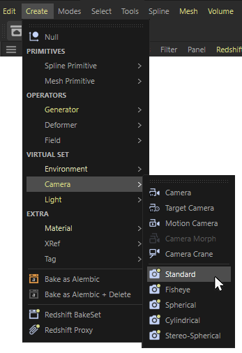
Native Redshift cameras can be added from the 'Create' menu.
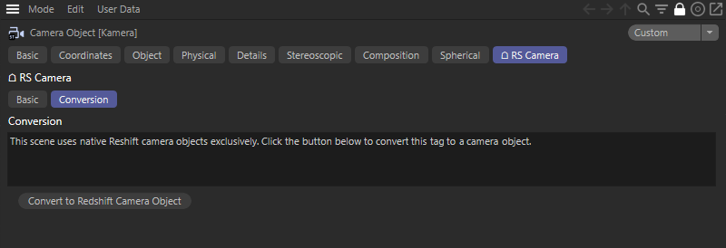
Redshift Cameras should only be used in new projects and not in combination with Cinema 4D cameras that use the Redshift Camera tag. In this case the Redshift Camera tags will get deactivated and offer a new button to convert the Cinema 4D camera object and its Redshift Camera tag to the new Redshift camera object (see image below).
If you need to work on an older Redshift project and add a Cinema 4D camera/Redshift Camera tag combination there, you can open the Cinema 4D Preferences from the Edit menu and open the settings for Renderer/Redshift. There you can find the option for Native Camera for New Scenes. Deactivating that option will still create Redshift Camera tags for new camera objects. You can learn more about the Redshift Renderer Preferences here.
Converting camera types
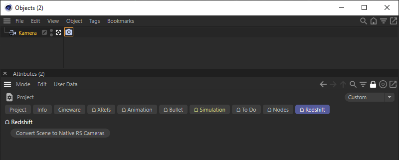
If you already created a standard Cinema 4D camera object or have an older scene with a Cinema 4D camera in combination with a Redshift Camera Tag, you can use the Convert Scene to Native RS Cameras button, that is found in the Redshift tab of the Cinema 4D Project Settings. The Project Settings can be opened from the Cinema 4D Edit menu or by using the Shortcut Ctrl-D.
Many of the settings of a Redshift Camera are already known from the Cinema 4D camera object. Nevertheless, there are also functions here that are only available when rendering with Redshift.
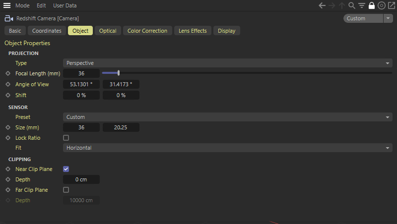
Object
In this settings group you will find the most common camera options, including focal length and the ability to change the type of camera itself.
Projection
Type
In this menu the projection type of the camera can be changed between things like a standard perspective camera or more specialized cameras like fisheye and stereoscopic.
For a normal camera perspective, select Perspective. The perspectives Fisheye, Spherical, Cylindrical and Stereo Spherical simulate very wide-angle lenses or even perspectives that cannot be captured with real cameras. These perspectives can be useful for creating panoramic renderings or VR environments, for example.
Here you can find more information about these perspectives.
The following perspectives, such as Right, Front or Top represent the standard viewing directions and perspectives of the 3D viewports
When switching to Orthographic perspective, the camera uses a parallel perspective, comparable to the standard viewport viewing directions. The difference is that the camera can still be freely placed and rotated in space.
The Isometric perspective is offering a fixed camera perspective and results in equally foreshortened axis directions with an angle of 120 degree between any pair of axes.
Finally the Dimetric perspective also offers a fixed viewing direction, but the camera can still be moved. Parallel edges remain visually parallel and the lengths along the X and Y directions remain proportional. Only the distances along the Z axis appear shortened.
All Orthographic, Isometric and Dimetric perspectives offer a Zoom value to control the visual size of the objects
Focal Length (mm)
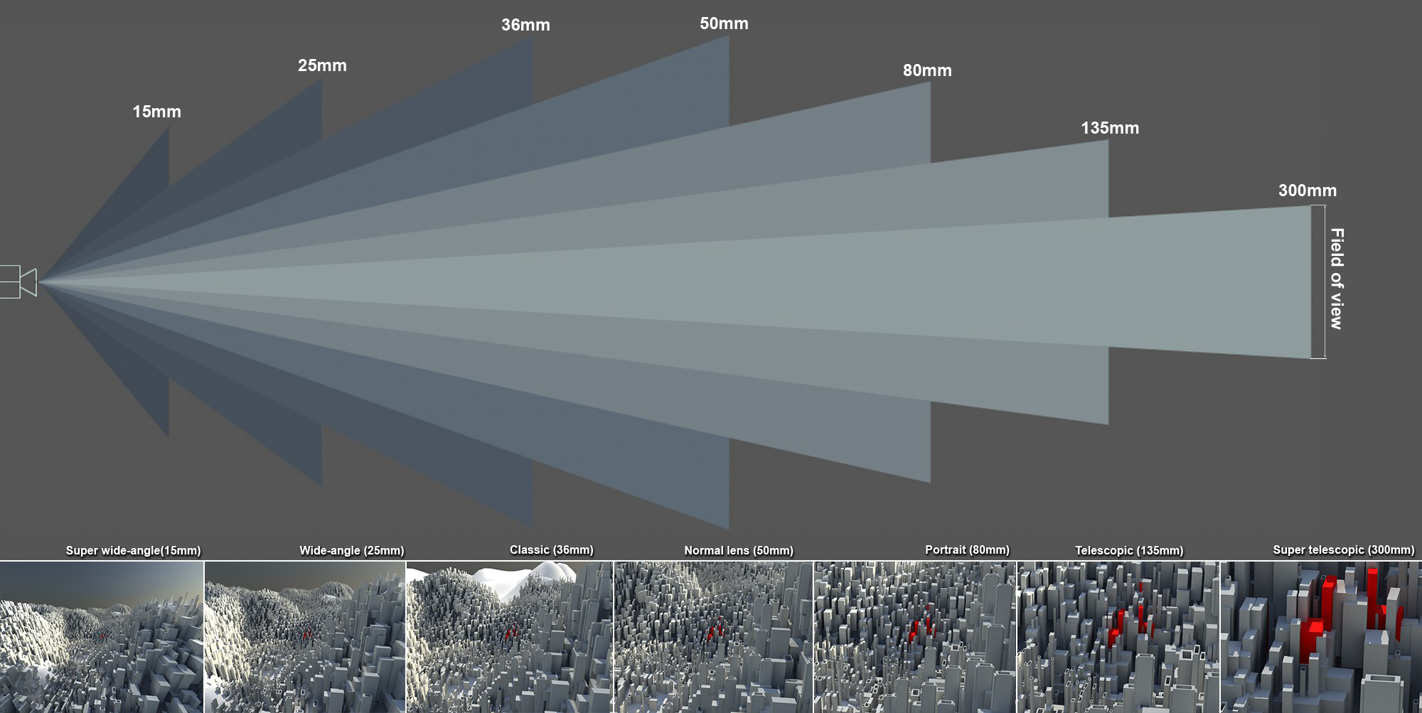
In a real camera, the focal length represents the distance between the lens and the sensor. Small focal length values are used for wide-angle shots and present a wider view of the scene, but also distort the image (especially very short focal lengths). Larger focal length values zoom into the given scene accordingly. The greater the value, the less distorted the image will be until the perspective effect is lost completely with extremely large focal length values and the parallel projection effect increases.
|
|
Influence of the focal length on the perspective and the representation of the objects
|
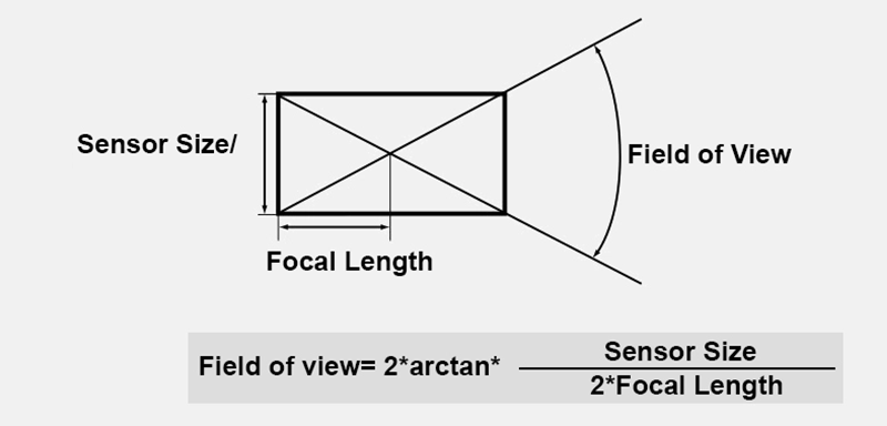
The Focal Length is directly linked to the Angle of View in the formula illustrated below and works for the horizontal (X) and vertical (Y) direction. Larger Focal Length values produce a smaller field of view and vice versa.
Angle of View (X/Y)
The field of view represents the camera's horizontal and vertical angle, respectively, to the scene. The field of view is directly linked to the focal length. The greater the focal length, the smaller the field of view and vice versa. A small field of view represents a camera with a telephoto lens; since only a small portion of the scene to be photographed enters the camera, this portion naturally appears very large on the light-sensitive surface of the camera, resulting in a zoomed-in image.
Incidentally, Field of View changes if the proportion between Width and Height are modified in the Render Settings.
Shift (X/Y)
Suppose the Redshift camera worked like a traditional, analog film camera, with images being recorded onto photographic film one after the other. Now imagine if additional image information could be recorded by moving this film along the X and Y axis. This is exactly what these parameters do. Redshift takes this one step further in that it does not restrict itself to the size of the filmstrip.
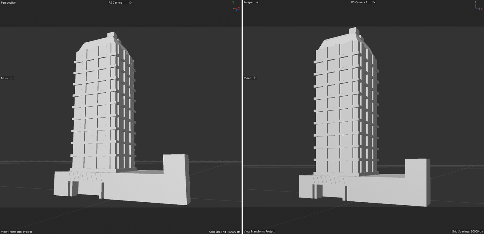
This can be very useful as it lets you move the rendered objects without changing their perspective. Objects that might have been placed too close to the border of the rendered frame can be visually moved more towards the center of the image. Another application is the correction of vertical lines in architectural renderings. In such cases, rotate the camera so that the scene horizon passes exactly through the center of the image (P-rotation = 0°). By using the Shift Y component, you then shift the horizon back to the desired height in the image. The vertical lines are preserved because there is no third vanishing point above or below the horizon.
|
|
On the left side, the camera is tilted slightly upward to mimic the view of a pedestrian. This results in an often undesirable skewing of the vertical lines in architectural renderings. On the right side, the camera has a P-rotation of 0° and uses only the Shift-Y component to move the building down in the image. The vertical lines now remain undistorted.
|
Sensor
The sensor of a camera is usually a fixed element that evaluates the incident light. In conjunction with the focal length, the size of the sensor determines, among other things, the field of view of the camera.
The aspect ratio of the sensor can be set freely, but does not necessarily affect the aspect ratio of the rendering. This is defined exclusively by the render resolution that you set in the Render Settings.
If you like to reuse different Sensor Size settings, the Preset menu offers commands to add or delete presets for them.
Preset
In this menu you can manage various presets for the sensor size. The currently set sensor size can be saved here with an individual name using the Add Preset menu item and thus accessed again at any time. Entries that are no longer required can also be deleted from the list by selecting Delete Preset.
Size (mm)
Here you set the size of the sensor in X and Y direction. If you want to keep the existing aspect ratio when resizing, activate the Lock Ratio option.
Both values are not necessarily required. The following Fit menu controls how the Sensor Size is to be evaluated.
If you like to reuse different Size settings, the Preset menu offers commands to add or delete presets for them.
Lock Ratio
Activate this option if you like to keep the ratio of the sensor size during editing.
Fit
Here you select the dimension of the sensor which, in conjunction with the selected render resolution and Focal Length, define the Angle of View (X/Y) on the camera.
- Fill-Crop: The ratio of X and Y size of the sensor is set in relation to the render resolution. For example, if you have selected an Film Aspect of 4:3 for the image resolution and are using a sensor that has an aspect ratio of 4:2.5, the X-size of the sensor is used to calculate the horizontal field of view in this case. If, on the other hand, the aspect ratio of the sensor were, for example, 4:3.1, the Y-size of the sensor would control the vertical field of view.
- Horizontal: Only the X-Size of the Sensor Size is used
- Vertical: Only the Y-Size of the Sensor is used
- Overscan-Fit: Always the smaller sensor length compared to the Film Aspect from the Render Settings is evaluated. If a Film Aspect of 4:3 is rendered and the sensor size is 40 * 29 mm, the 29 mm sensor height is used as the basis for calculating the angle of view. If the sensor size is 39 * 30 mm, the width of the sensor would be evaluated instead in this example.
- Square: This mode is using the default 36 mm * 27 mm Sensor Size used in full frame photographic cameras. In case your render resolution is not using a 4:3 aspect ratio, only the x component of the Sensor Size is used for the Angle of View calculation.
Zoom
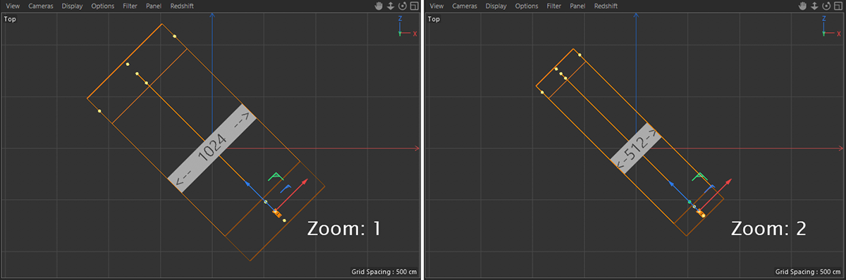
The Zoom value can only be defined if a parallel perspective (this includes orthographic views) is used. This setting then defines the scaling of the view.
The default value of 1 will always cover an area of 1024 units on the horizontal axis.
|
|
On the left a Zoom of 1 covers a viewing area of 1024 units along the X-axis of the camera. On the right, if you double the Zoom to 2, the horizontal viewing area is halved .
|
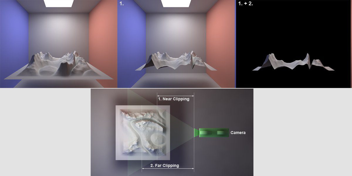
Clipping
Use the Near Clip Plane and Far Clip Plane options to specify two distances (Depth values) measured from the camera position. Only geometry between these distances is evaluated for display and rendering.
Near Clip Plane
Depth
Far Clip Plane
Depth
This setting defines cutting planes that lie perpendicular to the angle of view of the camera. The Near Clip Plane will remove all geometry that is closer to the camera than Depth. The Far Clip Plane will ignore all geometry that is further away from the camera than defined by its Depth value. Note, however, that these objects will remain closed for the renderer with most effects. Shadow casting light sources cannot illuminate the interior of such cut objects. When applying Far Clipping, the Background can be used to avoid rendering objects that lie in cut off regions at the rear of the scene black by default.
Use the Depth values to define the distances from the camera to the given cut plane. In the Display tab of the camera object, you can also find the options for Near Clip Plane and Far Clip Plane, to draw additional frames for these distances in the viewport.
|
|
The top row shows the original scene on the left. The image next to it shows the effect of a Near Clip Plane, cutting off the forground part of the landscape object. The image on the top right additionally uses a Far Clip Plane, cutting away all of the walls in the background and the back half of the landscape.
|
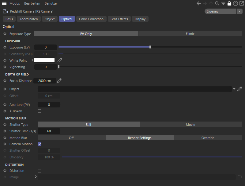
Optical
These settings control the exposure and other common optical effects like bokeh depth of field, vignetting, white balance, and lens distortion.
The Optical settings are not compatible with the Cinema 4D default camera and the Optical menu will not be visible in its usual spot in the Redshift Render View.
Please create a Redshift Camera Object to access these settings.
Exposure Type
Choose how you would like to use the following parameters:
- EV only: Sensitivity (ISO), Aperture (f/#) and Shutter Time/Shutter Angle will not affect the exposure of the rendering. This way you can use these settings to just control Depth of Field and Motion Blur. To brighten or darken the rendering, use the Exposure (EV) value.
- Filmic: Sensitivity (ISO), Aperture (f/#) and Shutter Time/Shutter Angle will work a with a regular still or movie camera and not only control Depth of Field or Motion Blur, but also the exposure of the rendered image.
Exposure
Exposure (EV)
You can use this value to multiply the amount of light in your scene. A value of 0 will keep all light intensities untouched. An Exposure (EV) of 1 will double the intensity of the light in the scene, while an Exposure (EV) of -1 will cut all intensities in half.
Sensitivity (ISO)
This value describes the sensitivity of a negative film or camera sensor to light. In real-life high ISOs mean that the film is very sensitive and will capture a lot of light in a short amount of time, but the image can be grainy. Low ISOs mean that the shutter has to be open for longer for the film to capture enough light (otherwise the image will be too dark) but the final result will be cleaner. Please note that Redshift does not simulate the chemical properties of film or the noise of an image sensor, so there will be no problems with grain at high ISO settings! This value is only available for Exposure Type "Filmic".
White Point
Use this value to prevent colored light sources (e.g., sky, sun, candles, etc.) from colorizing white surfaces. Set the White Point color to the color of the light source's color.
Note that you can also use this parameter to color your rendering, by using the Color Wheel input to choose the complimentary color. For example, a bluish color will result in a warm colored rendering.
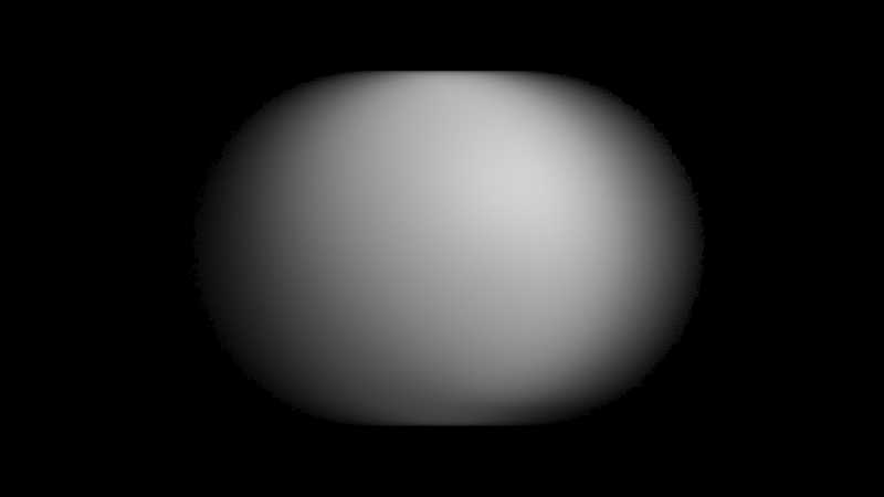
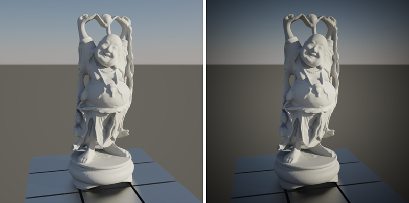
Vignetting
In real-life, light has to travel through a camera lens before it reaches the film or sensor. Lenses are often imperfect and, depending on the angle of the lighting, they might absorb or reflect away some light so less of it eventually reaches the camera. The result is darkening around the edges of the image. This imperfection, however, can sometimes be visually pleasing and 'focuses' the viewer towards the center of the image.
The higher the Vignetting value, the more darkening there will be around the edges of the image.
|
|
On the left, rendering without the vignetting effect and on the right the same scene with vignetting.
|
Depth of Field
These settings let you control the transition between in focus and out of focus elements in your rendering.
Focus Distance
This value is only used if the Bokeh option is active.
The Focus Distance, measured from the camera's origin out (= film or sensor plane), defines the spacing to a plane that lies perpendicular to the angle of view, on which all objects are displayed perfectly in focus. In front of and behind this plane, all surfaces are rendered progressively blurred, based on the Aperture (f/#) value.
The Focus Distance can be defined interactively with the mouse in the Viewport by clicking and dragging on the camera's center front handle, or you can activate the Picker icon next to the Focus Distance and click on the surface in your viewport that should be in perfect focus. The distance towards the clicked position will be entered to the Focus Distance field automatically.
|
|
The Focus Distance plane can also be made visible in the viewports by activating "Focus Plane" in the "Display" tab of the camera. Here it was colored dark purple.
|
Object
Instead of entering a value for the Focus Distance you can also link to any object here, by dragging an object from the Object Manager to this field. The distance between the camera position and the position of the linked object will be used as Focus Distance. This is especially usefull for example during animations, to keep a specific position in focus, even if the camera is moving. You can also use an animated Null object to drive the Focus Distance.
Offset
When using the Object link field to use the position of an object as Focus Distance, you can manually tweak this Focus Distance by entering an Offset value.
Aperture (f/#)
The Aperture value (F-stop) is used to adjust the focal aperture. The larger the focal aperture (i.e. the smaller the Aperture value), the smaller the depth of field will be and vice-versa. So in short, smaller Aperture values result in stronger blur for surfaces that are further away from the Focus Distance plane. If the Exposure Type 'Filmic' is enabled, Aperture (f/#) will also define the amount of light that can enter the camera. Smaller values will then result in brighter renderings.
All blurry effects based on the Focus Distance and the F-Stop value are only calculated, if the Bokeh option is active!
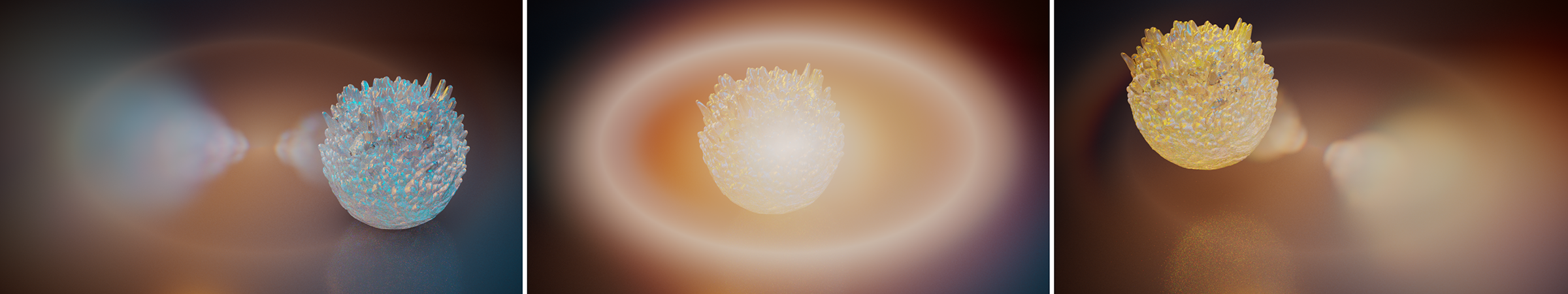
Bokeh
Activate this option to calculate blurry effects for out of focus elements in your scene.
|
|
On the left you can see the original scene, rendered without the Bokeh effect. The two images on the right show the same scene, this time with active Bokeh calculation. The change between the two images on the right is just caused by different F-Stop values.
|
Diaphragm
Ideally, the aperture of a camera lens corresponds to a circle. This results in surfaces lying in the blur appearing magnified in a circle. This can be observed particularly well on small, bright areas, such as those created by highlights or intense reflections.
In reality, however, the aperture opening is shaped by individual blades that allow the aperture size to be changed. You control this size via the Aperture (f/#) value. By using blades, the perfect circular shape can only be approximated, depending on how many blades are installed. Accordingly, the use of 6 blades, for example, results in a hexagonal opening rather than a circle, and the areas lying in the blur are displayed hexagonally enlarged.
If this approach is pursued further, arbitrarily shaped apertures would also be conceivable in principle, which would then also lead to correspondingly shaped blurs.
These three options, a perfect circle, an aperture limited by straight blades, and an arbitrarily shaped aperture, are also available on the Redshift camera by choosing between the modes Circular, Bladed and Image.
Aspect
This parameter can squash the depth-of-field effect and simulate the effect observed on anamorphic lenses. Values below 1 stretch the bokeh vertically, values above 1 stretch the bokeh effect horizontally. A value of 1 preserves the original proportions of the bokeh effect.
|
|
The image on the left shows Bokeh with an Aspect of 0.5, while the right image is rendered with an Aspect of 1.5.
|
Spherical Aberration
With this value you can influence the brightness distribution within the bokeh spots. With small values, the brightness is concentrated more in the center of a bokeh spot. With larger values, on the other hand, the center can remain dark and the outer border of each bokeh spot appears particularly intense. The following images demonstrate this for three-sided bokeh (3 blades).
|
|
The image on the left shows a small value for Spherical Aberration, resulting in a centered brightness. With larger values, the outer borders of the Bokeh appear brighter than the center.
|
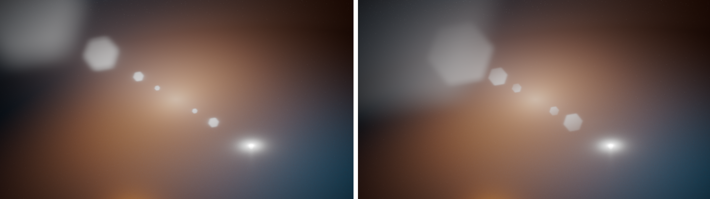
Blades
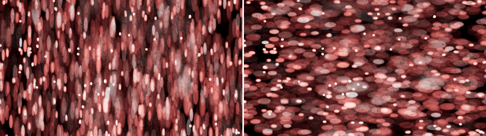
This setting is only available for Diaphragm Bladed and sets the number of blades for the simulated aperture opening. The images below show possible results, using different amounts of blades.
|
|
The image on the left was rendered with three blades, the image on the right uses six blades.
|
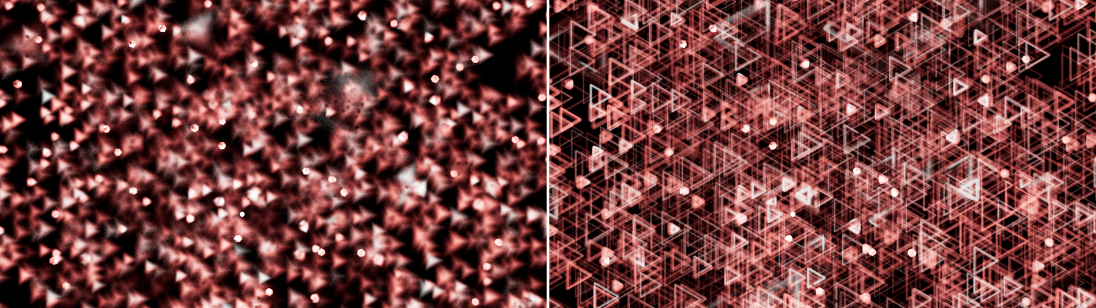
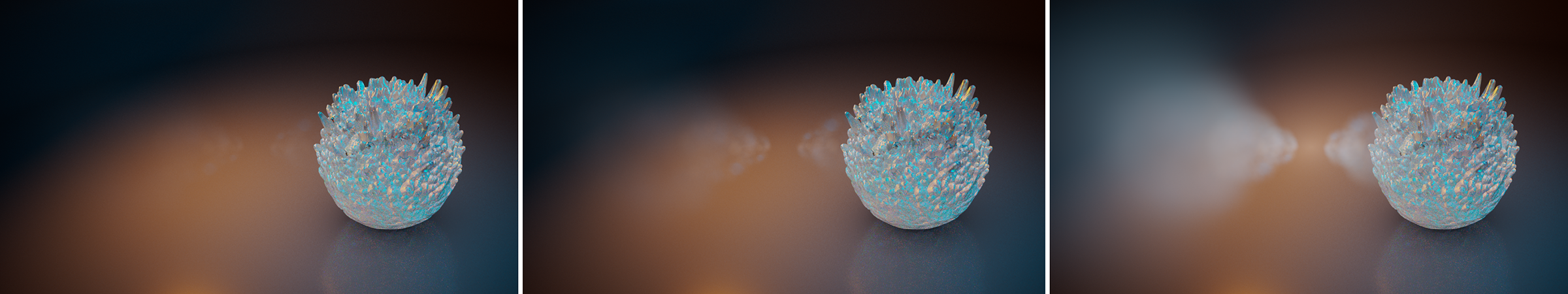
Note that the orientation of the bokeh shape changes depending on the position relative to the plane of focus. The bokeh shapes that lie behind the plane of focus are calculated mirrored vertically and horizontally. This also corresponds to the real representation of bokeh in traditional photography or filming.
|
|
The image on the left shows only the Bokeh effect between the camera and the Focus Plane. The right side shows the Bokeh effect behind the Focus Plane. The Bokeh shape appears mirrored there.
|
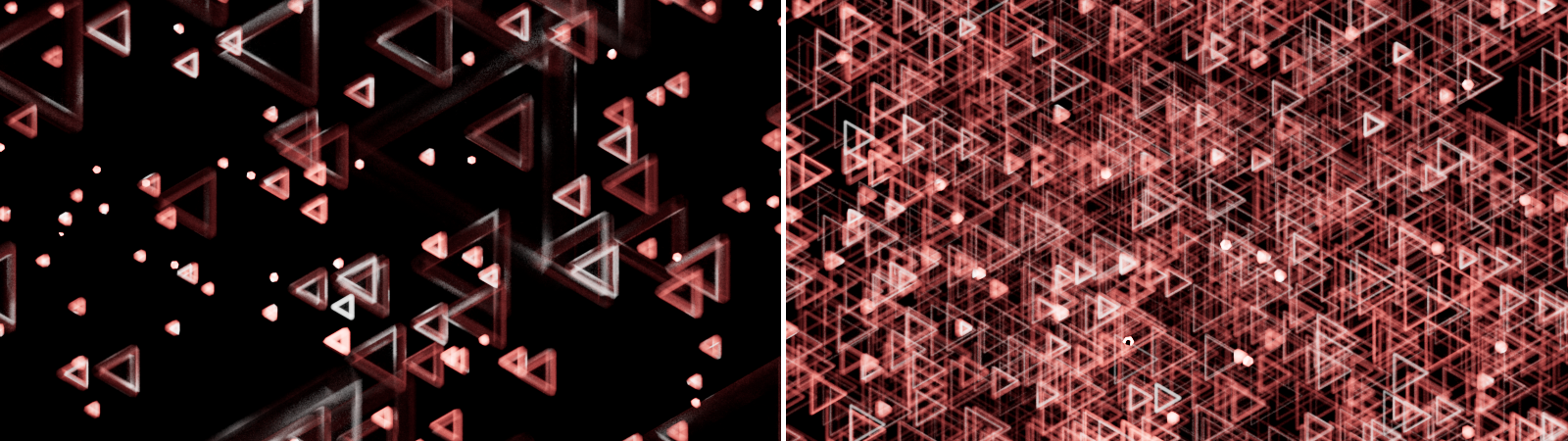
Angle
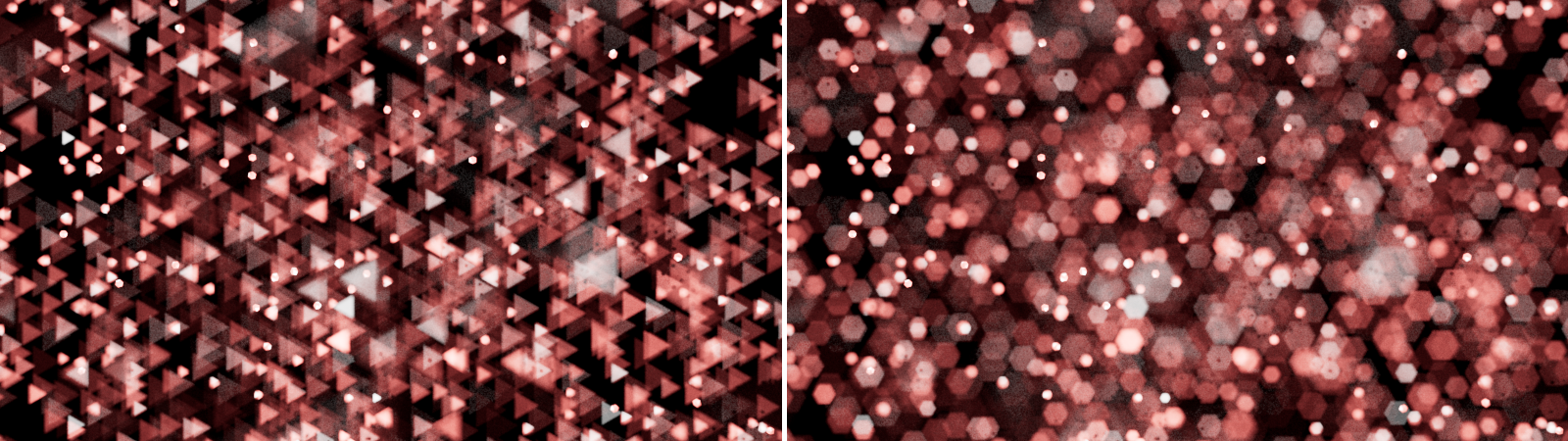
This value allows you to rotate the Bokeh shape in Diaphragm Blades mode. Take note, that to direction of rotation is different for the Bokeh shapes in front of the Focal Plane (counterclockwise) compared to the Bokeh shapes behind the Focal Plane (clockwise).
|
|
From left to right these images show Bokeh with three Blades, using a 0°, a 45° and a 90° Angle value.
|
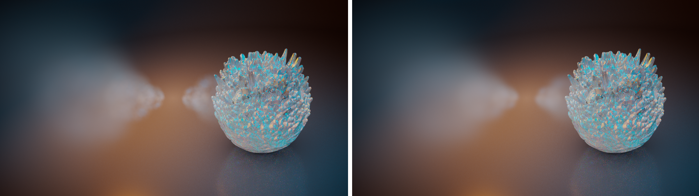
Image
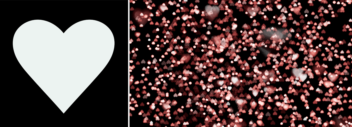
When using Diaphragm Image you can use this input to load a bitmap. A loaded image can be a simple black and white mask to shape the Bokeh effects, as shown in the image below.
|
|
In this example, a bitmap with a white heart shape on a black background was loaded as an Image and shapes the Bokeh effects.
|
As you can see in the images above, the loaded image is used mirrored along the vertical and horizontal direction when used on the Bokeh effects located behind the Focal Plane.
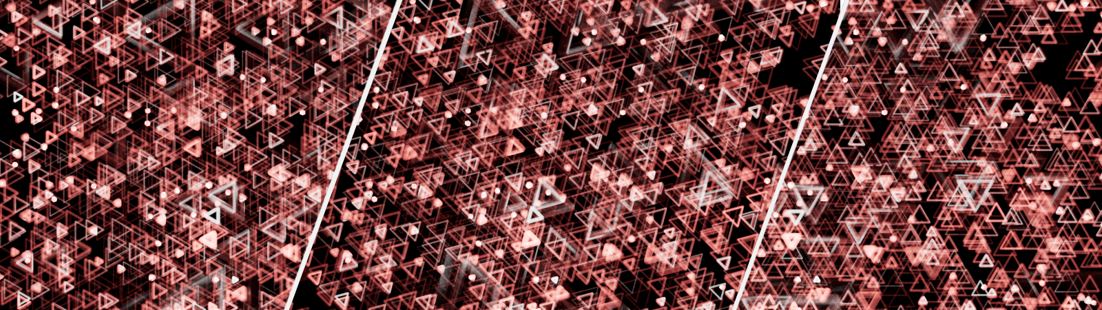
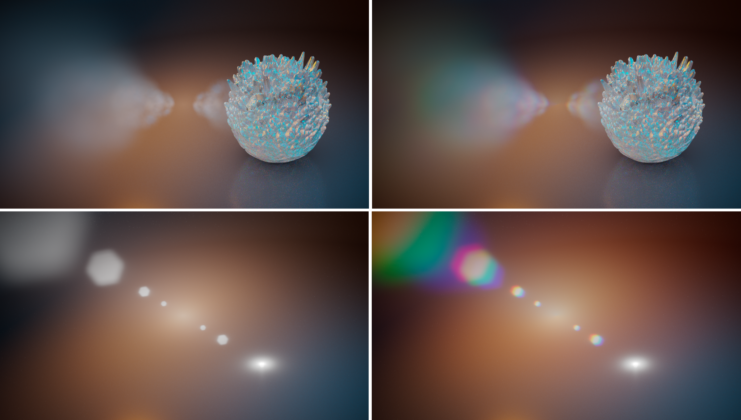
Real-life camera lenses sometimes also exhibit an artifact called "chromatic aberration". Chromatic aberration means that, depending on the angle of the light reaching the lens, certain light wavelengths (colors) are reflected away and never reach the sensor or film. This creates a rainbow effect which is stronger in parts of the image that are out-of-focus. This kind of effect can also be recreated by using an Image for Bokeh, as you can see below.
|
|
Images likes this one can be used to simulate chromatic abberation.
|
Normalization
This setting determines how to handle the colors and brightnesses of the loaded image. For example, if a colored image as shown above were used to simulate chromatic aberration, the parts of the rendering in focus should still remain neutrally colored.
To get a neutral result in the focused pixels one would have to draw this picture perfectly. I.e. there should be exactly the same number of red pixels to blue to green. Not doing so would mean that the image would either be too red or too green or too blue and also too dim.
But drawing such an image is almost impossible to do! So, for that reason, Redshift offers several Normalization modes to balance out the different colors of a loaded image:
- Off: The loaded image is used as it is. If all used colors don't add up to "white", the rendered Bokeh will be darker and you might see a color shift in the rendering due to the different amounts of red, green and blue pixels in your loaded image.
- Sum to White: If you want to ensure that the colors you use all add up to white, use this mode.
- Unit Intensity: This is the right mode, if the overall tint is not white, but you still want the final image to not be any darker than it would normally be.
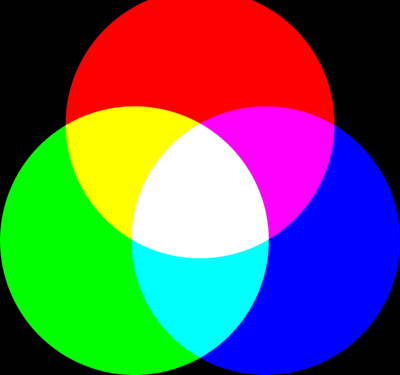
The colorful bokeh image shown above actually suffers from several issues. It contains black, so it means that it doesn't sum to white. Also the red/green/blue circles are not perfect: the red circle has its top chopped off, so there is less red in this image compared to the green and blue pixels. But using the normalization modes, this image can still be used without issues!
|
|
|
Normalization: Off
The in-focus pixels are tinted and look darker |
Unit Intensity
The image is brighter but there is still tint because of the red circle being chopped off
(so green and blue 'win'). |
Sum to White
The image is now normalized so that all its pixels add up to white. This removes any unwanted tinting in the in-focus pixels |
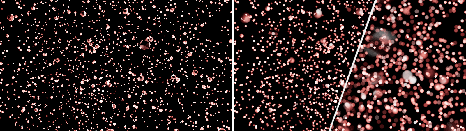
Motion Blur
Shutter Type
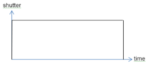
The shutter determines the time period in which light falls into the camera or onto the sensor. There are two different concepts for specifying this exposure time:
- Still: This is the classic behaviour of digital still or movie cameras. The shutter speed is specified in fractions of a second ('Shutter Time'). The 'Shutter Offset' is defined in fractions of a second.
- Movie: On traditional film cameras, the shutter is formed by a disc rotating in time with the frame rate. Inside this disk is an opening whose size is specified by the 'Shutter Angle'. This concept takes care, that the shutter is always in sync with the current frame rate so changing the frame rate will always result in a correct shutter speed for animations. The 'Shutter Offset' is defined in degrees too.
Shutter Time (1/s)
This parameter controls the duration the camera's shutter will stay open in Still mode. A value of 30 means 1/30, i.e. a 30 th of a second. Therefore, the smaller the value, the longer the shutter stays open. In combination with the Filmic Exposure Type, using a longer Shutter Time will result in a brighter rendering. On the other hand, a longer Shutter Time also results in more blur for moving objects, if the cameras Motion Blur option has been activated.
Shutter Angle
This setting is available in Movie mode. Movie cameras use a rotating shutter disc, that is doing a full 360° rotation for every recorded frame. This rotating disc has an opening to allow light to enter the camera. The Shutter Angle defines the size of the opening relative to the 360° rotation. A 180° Shutter Angle in combination with a 30 fps recording would result in a 1/60 of a second shutter time (1s/30fps * 360°/180°). Changing the frame rate will always provide a correct shutter speed for animations. Used for filmic exposure and motion blur. With Filmic Exposure, larger Shutter Angles will result in brighter renderings.
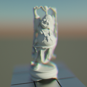
Motion Blur
Since cameras always capture and evaluate light through the sensor over a certain period of time, blurring occurs on objects that move relative to the camera during the exposure. The intensity of this motion blur depends on the relative speed of the objects and the exposure time. These options are available:
- Off: No Motion Blur will be calculated during rendering
- Render Settings: Motion Blur will be rendered, if it has been activated in the Render Settings. The Motion Blur settings from the Render Settings will be used.
- Override: Motion Blur will be rendered, if it has been activated in the Render Settings. The cameras settings for Motion Blur are used.
|
|
On the left are spheres with individual velocities moving on circular paths. Without Motion Blur, this motion cannot be seen in a still image. On the right you see the same image, only this time rendered with Motion Blur. The different speeds of the spheres are clearly visible.
|
Take note, Render Settings offer additional controls for the calculation of Motion Blur and Motion Blur must be enabled there for rendering as well!
By using the Redshift Object Tag individual Motion Blur settings can be applied on a per object basis if needed.
Motion Blur is not visible while rendering in the standard viewports or while rendering with RT or IPR. You have to render to the Picture Viewer or do a final render in the Redshift Render View.
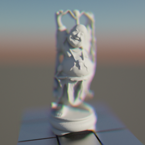
Camera Motion
In real-world conditions, motion blur occurs whenever something moves relative to the camera. For example, imagine you are sitting in a train filming the landscape out the window. Although the landscape itself is still, your images will contain motion blur because the camera has moved relative to the landscape during the exposure. If you only want to see motion blur when the objects you are rendering are themselves in motion, turn this option off.
|
|
Both images are rendered with motion blur, showing rotating spheres as seen from a camera that is passing by. The left side shows how the motion of the camera and the motion of the spheres add up, when 'Camera Motion' is active. With this option switched off, only the motion of the spheres is evaluated for the motion blur calculation (right image)
|
Shutter Offset
This offsets the opening and closing of the shutter and can be useful for matching footage or for fine tuning the motion blur, e.g. in particle situations or animations. In Still mode, you specify a fraction of a second here. In Movie mode, you specify an angle at which the rotating shutter disk is to be rotated.
Efficiency
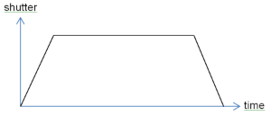
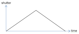
Real-life camera shutters don't open instantaneously – they open gradually. The Efficiency parameter controls how fast the shutter opens. A setting of 1.0 means the shutter will open instantaneously, while a setting of 0.0 means that it will open as gradually as possible. The images below show how the Efficiency parameter affects the shutter opening speed.
The Efficiency parameter affects the look of motion blur trails, as it will be shown in the example pictures below. The smaller the Efficiency is, the softer the motion blur trails will appear.
Distortion
Distortion
Due to their lens geometry, real-life cameras tend to distort the captured images. If the user needs to add CG elements to real-life (distorted) camera footage, the CG elements will also have to be distorted. To be able to control this effect, activate this option and load an RGB image to the Image slot.
Image
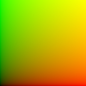
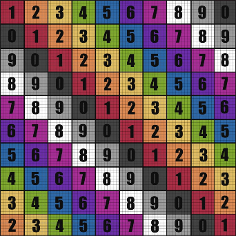
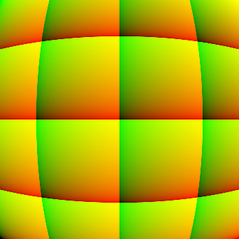
The distortion is calculated by UV coordinates, projected onto the rendered scene. The U direction is represented by the color red (1, 0, 0) and the V direction is represented by the color green (0, 1, 0). Therefore an image that wouldn't add any distortion to the rendering will look like this:
|
|
The calculation of distortions is based on an image that shows UV coordinates, by using red for the U direction (horizontal) and green for the V direction (vertical).
|
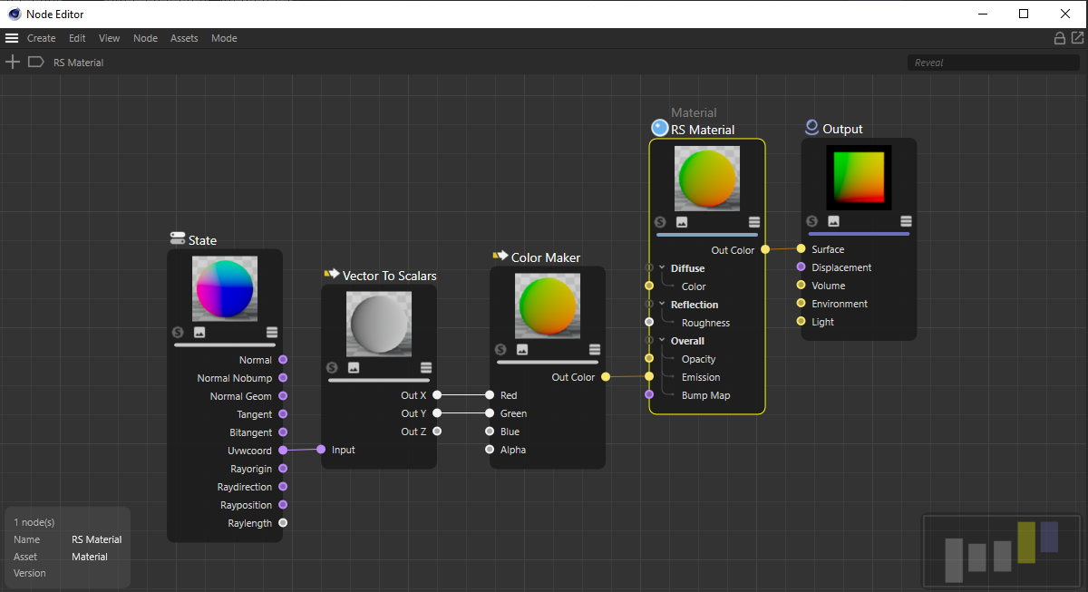
This type of image can easily created in Redshift by rendering a UV gradient on a plane. To achieved this use a State node and connect the "Uvwcoord" output to a Vector to Scalars node which then passes the "Out X" and "Out Y" to a Color Maker's "Red" and "Green" channels as seen in the example image below.
|
The following section offers a possible workflow to create your custom distortion map in Cinema 4D.
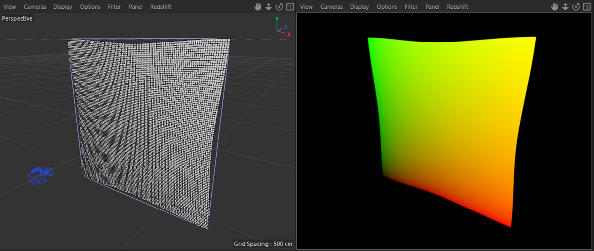
By using a simple plane primitive with our UV gradient material, we can now use any kind of deformation on this plane to distort the representation of the gradient. Be sure to deactivate any Reflection or Diffuse shading in the gradient material and use the calculated UV colors to set the Emission of the material. This prevents any additional shading of the colors on the plane object. Finally place a new camera in front of the plane and use an orthographic perspective for it (such as Front if the plane is in -Z Orientation).
The example below is using two Bulge deformation objects to distort the plane, but any other deformation or even manual sculpting with a tool will work as well. Just take care to adapt the cameras position and Angle of View values before rendering, so that the distorted plane is filling the complete rendering. No background should remain visible.
|
|
Create a Plane primitive and adjust its segment count, so is can be easily deformed and apply the UV gradient material to it.
|
When saving a UV Distortion image make certain to save it in Linear Color Space, so no Gamma curve is applied!
|
|
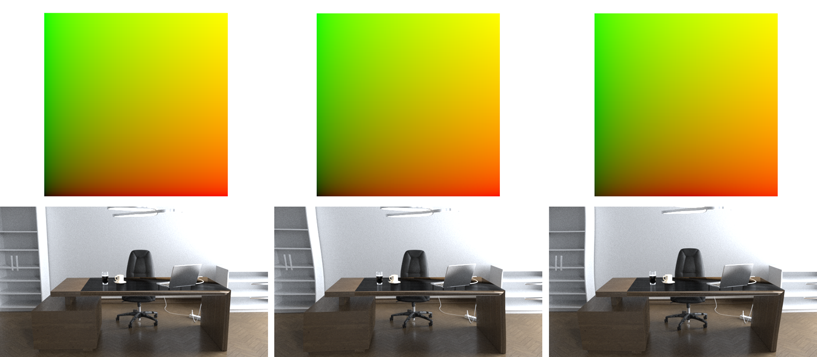
The left image shows the result after rendering with the standard distortion gradient and delivers the same result as rendering with 'Distortion' switched off. The two other renderings show the effect of using a negative and a positive strength. The example gradients only show very subtle differences, but the effect on the render is much more noticeable.
|
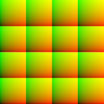
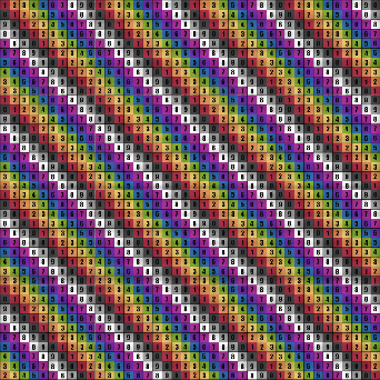
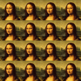
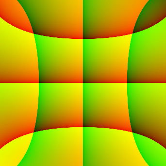
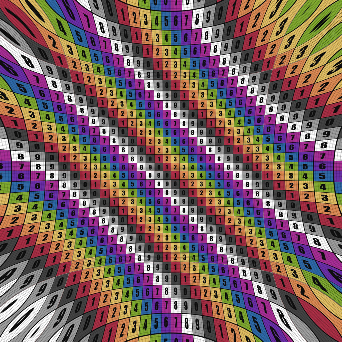
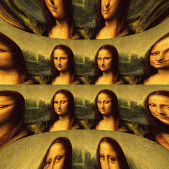
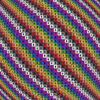
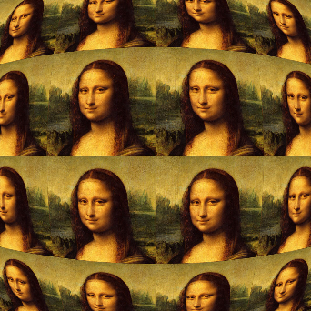
Using the same principle, even more complex distortions can be achieved as demonstrated in the following images. By repeating the standard red/green UV gradient several times in the loaded distortion image, the scene will also be arranged multiple times in the final rendering.
|
|
|
|
| Neutral UV Distortion Image |
UV Grid Rendering |
Image Rendering |
|
|
|
|
| UV Distortion Image |
UV Grid Rendering |
Image Rendering |
|
|
|
|
| UV Distortion Image |
UV Grid Rendering |
Image Rendering |
|
|
|
|
| UV Distortion Image |
UV Grid Rendering |
Image Rendering |
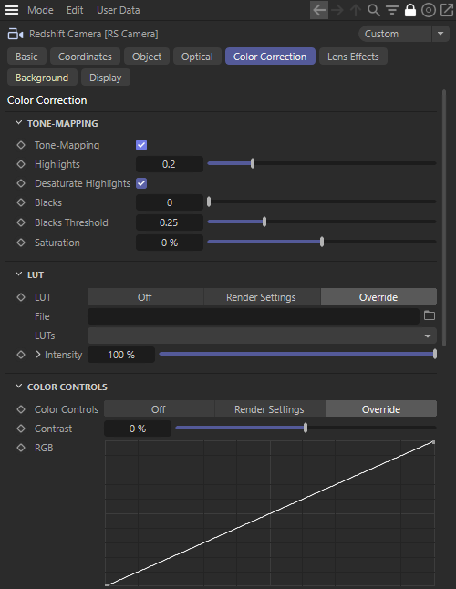
Color Correction
Most computer graphics displays can reproduce all colors ranging from black (0.0, 0.0, 0.0) to white (1.0, 1.0, 1.0), but often lights and other effects use values that go beyond (1.0, 1.0, 1.0). For example, physical sun can produce values that are in the thousands.
Tone-Mapping allows these very high values to be "remapped" to the "0.0 to 1.0" range that computer displays use in order to preserve fidelity without washing out the colors.
Tone-Mapping can also be used to decrease the brightness of darker pixels, resulting in a stronger image contrast.
Tone-Mapping
Tone-Mapping
Enable this option to gain access to additional controls for fine-tuning the brightness values and contrast in your render.
Highlights
This value controls what happens to high-intensity pixel values. It works by 'squashing' the high intensities into lower intensities in order to preserve fidelity that would normally be washed out white (because of these high intensities). A setting of 0.0 is the most aggressive setting. It means that lights or materials have to be extremely bright in order for the final pixels to approach the pure white (1.0, 1.0, 1.0) display color. Larger Highlights values are less aggressive and leave the original intensities more unaffected. A few different settings are demonstrated below:
|
|
|
|

|
|
Highlights: 0
|
0.25
|
0.5
|
1 (disables the effect) |
Desaturate Highlights
When enabled, the highlights of your image are automatically desaturated once they reach a certain threshold. This desaturation effect simulates what happens in real world cameras.
|
|
The image on the left was rendered with 'Desaturate Highlights' enabled, the right images had this option disabled. Notice how the yellow highlights are now more dull and closer to orange.
|
Blacks
Similar to how Highlights controls what happens to brightly lit areas, Blacks controls what happens in the dimmer parts of the image. It effectively squashes the darker colors in order to provide more contrast for images that have too much ambient lighting.
The Blacks value controls how much of the effect should be applied. A value of 0.0 means 'no crushing'. A value of 1.0 means 'maximum crushing'. To control, which brightness values are affected, use Blacks Threshold.
Blacks Threshold
This value controls at which parts of the input intensity range the crushing of darker pixels should happen. Low numbers mean 'only crush very dark intensities' while higher values allow more of the input intensity range to be black-crushed.
We demonstrate a few different settings in the images below. The Blacks Threshold was set to 0.25 so that only the darker parts of the image are affected by it.
|
|
|
Blacks: 0
Blacks Threshold: 0.25 |
0.25
|
1
|
Saturation
This controls the color saturation. The lower this value, the more grayscale the image. The neutral value is 1.0. If you set it to values higher than 1.0, the colors will appear more saturated.
LUT
LUT is short for Look-Up Table and applies a color transform to your render. A LUT file changes the RGB information in your render to a new range of colors to match a certain look as defined inside a LUT file.
Redshift supports *.cube and *.3dl LUT file formats.
LUT
- Off: No LUTs are used for rendering.
- Render Settings: The camera is using the global LUT settings from the Render Settings dialog. This is the default mode.
- Override: The local LUT settings from the camera dialog are used, even if the Render Settings are configured in another way.
File
Here you can load your *.cube or *.3dl LUT file. If the directory of this file contains other LUT files, you can browse this folder by using the LUTs menu.
LUTs
Here you can select and brows all available LUT files from the specified directory.
Intensity
This value sets the strength of the LUT color transformation. A value of 0% means no color changes occur and the LUT will have no effect on the rendered image.
|
|
|
|
LUT Strength: 0
LUT File: Fuji Neopan (Black & White) |
0.5 |
1 |
Convert to Log-Space before LUT
When enabled your rendered image will be converted to the logarithmic color space before the LUT is applied.
Apply Color Management before LUT
When enabled your Color Corrections will be applied to the rendered image before the LUT is applied.
Color Controls
The Color Controls section lets you make overall color and brightness adjustments to your rendered image.
Color Controls
- Off: No color controls are used for rendering.
- Render Settings: The camera is using the global color controls from the Render Settings dialog. This is the default mode.
- Override: The local color controls from the camera dialog are used, even if the Render Settings are configured in another way.
Contrast
Here you can increase or decrease your contrast.
RGB
The RGB curves feature allows you to tweak the brightness of your image on all color channels or the red, green, and blue channels individually.
|
|
|
|
| Color Curves: Neutral |
Strong adjustment in Red Channel |
Subtle adjustment in Green and Blue channels |
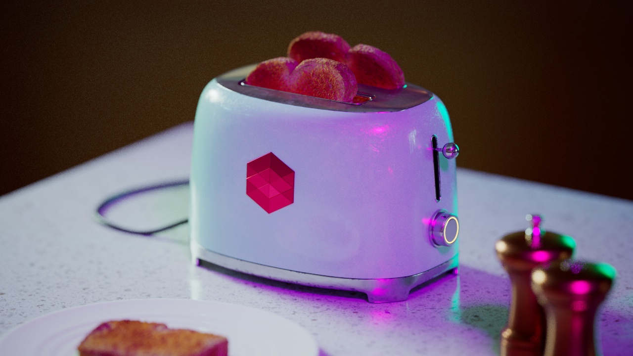
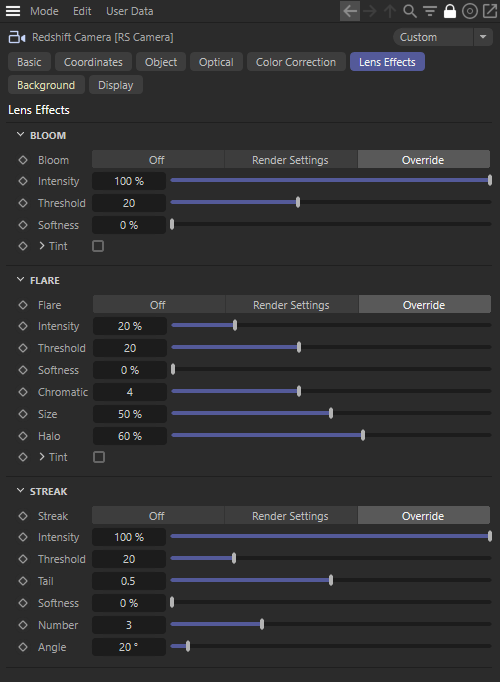
Lens Effects
These settings can be used to add optical effects that are typical of real camera lenses. These include inherently undesirable light scattering and light refraction within the lens system of a lens in the area of intense light irradiation. Although often undesirable in photography and filming, these effects can add realism or are often used deliberately as a stylistic element.
Bloom
This adds a glowing effect to bright areas and highlights of the rendering and can happen if you use a smudged lens with a real life camera.
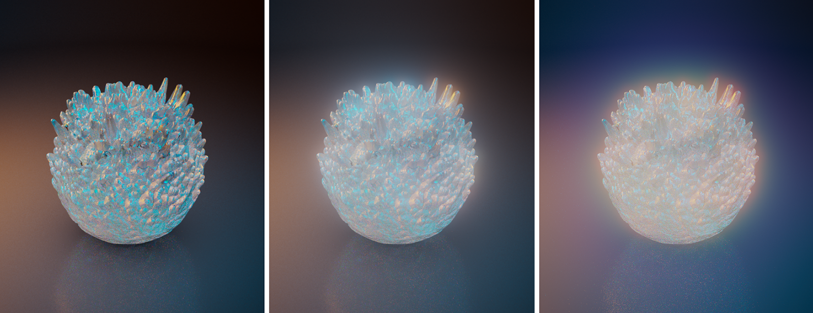
|
|
The image on the left was rendered without Bloom. The other two images use Bloom, while for the image on the right, individual Bloom 'Tints' have been activated.
|
Bloom
- Off: No Bloom effect is created for rendering
- Render Settings: The camera is using the global Bloom settings from the Render Settings dialog. This is the default mode.
- Override: The local Bloom settings from the camera dialog are used, even if the Render Settings are configured in another way.
Intensity
Use this value to scale the brightness and strength of the Bloom effect. Adjusting the Threshold value can also help control the amount and intensity of the blooming effect.
Threshold
This value determines from which pixel brightness blooming occurs. With smaller values, blooming already appears with less bright pixels. This means that the effect will be visible more often in the rendering.
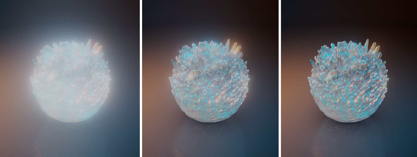
|
|
From left to right, using a Bloom 'Threshold' of 1, 3 and 6
|
Softness
This can be used to control the size of the blooming effect. It also makes the blooming appear softer and covers additional areas of the image.
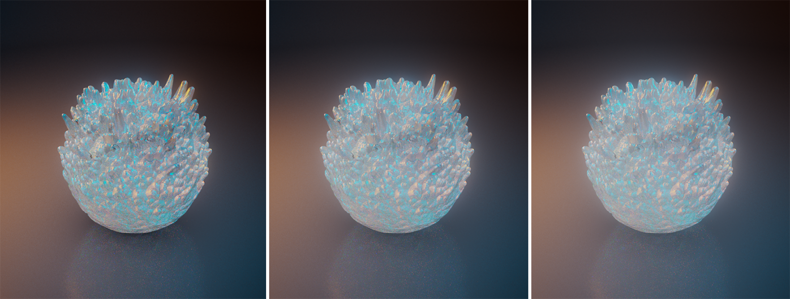
|
|
From left to right, using a Bloom 'Softness' of 0%, 20% and 40%
|
Tint
By default, blooming takes over the coloring of the bright areas of the image that triggered the effect. However, by activating this option you can also assign your own colors, like up to five, to color the blooming gradient from the inside to the outside. Tint 1 colors the bright center and Tint 5 the border area of the blooming effect.
1/2/3/4/5
If Tint is active, you can use these to color the Blooming effect from its bright center (1) to the outer radius (5).
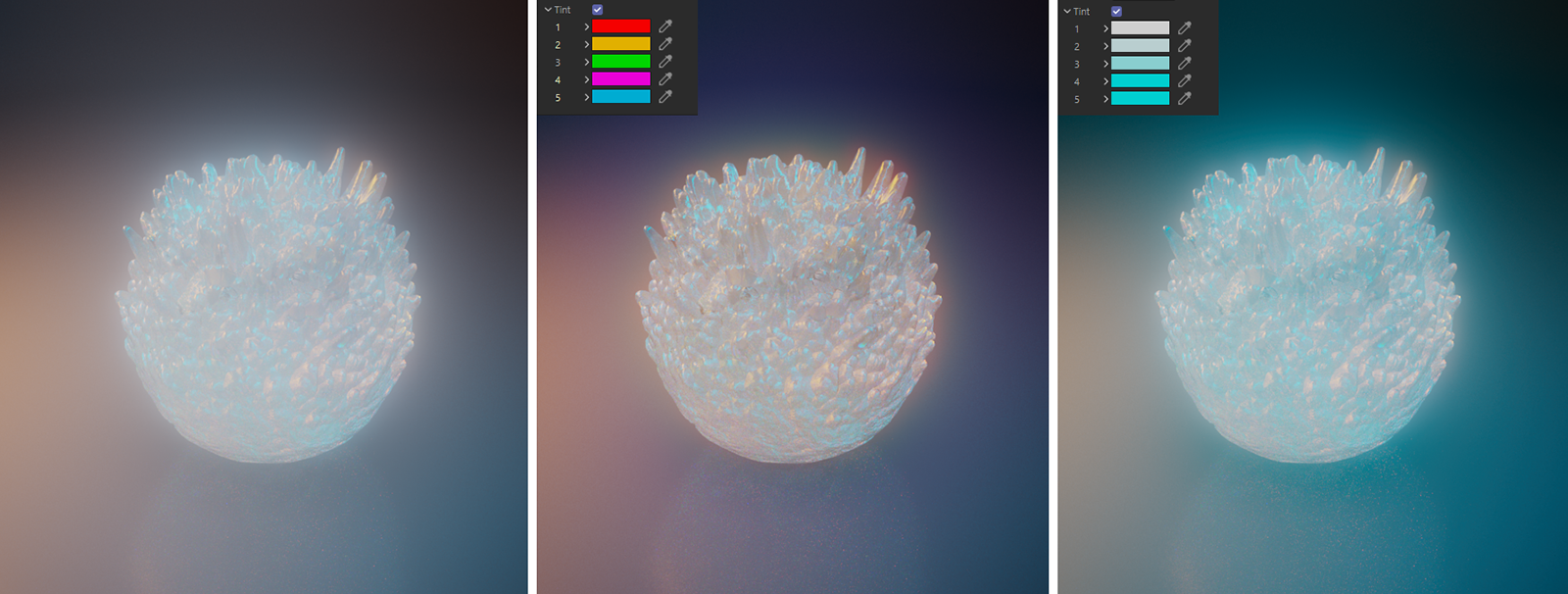
|
|
The left image shows the standard Bloom, without individual 'Tint'. The other images are rendered with different tint colors.
|
Flare
Lens Flares are caused by multiple reflections of bright specular highlights or surface reflections on the glass lenses inside the camera lens. This creates different colored shapes that correspond to the aperture opening. By default, these are perfect circles. The flare shapes are placed along a line that runs through the center of the image and the bright areas of the image. The Flare Lens Effect can also calculate a separate Halo ring that is always placed centered in the image and matches the proportions of the render resolution.
|
|
Variation of Flares, created just by moving the object in the scene.
|
Flare
- Off: No Flare effect is created for rendering.
- Render Settings: The camera is using the global Flare settings from the Render Settings dialog. This is the default mode.
- Override: The local Flare settings from the camera dialog are used, even if the Render Settings are configured in another way.
Intensity
Use this value to set the opacity of the Flare rendering.
Threshold
This value determines which pixel brightness must be reached for Flares to occur. Smaller values mean that even lower brightnesses are sufficient to contribute to the calculation of Flares.
|
|
From left to right, the 'Threshold' values 10, 5 and 1 were used here.
|
Softness
This adds additional blur to the Flares, as you can see in the images below. This effect is often rather subtle.
|
|
On the left rendering, a 'Softness' of 0% was used. The right images uses 100% 'Softness'.
|
Chromatic
By default, the Flares take on the color of the bright pixels on which they are based. This option simulates the natural effect of lenses that are not optimally coated, on which the light is refracted differently depending on the color. This results in the typical rainbow colors that we can also observe, for example, in the dispersion effects.
|
|
For the renderings on the left, a 'Chromatic' value of 0 was used. The Flare colors are only based on the pixel colors. The right images use the 'Chromatic' value 10.
|
Size
Use this to scale the individual Flare elements.
|
|
The left image uses a 'Scale' of 0% and the image on the right has a 'Scale' of 100%.
|
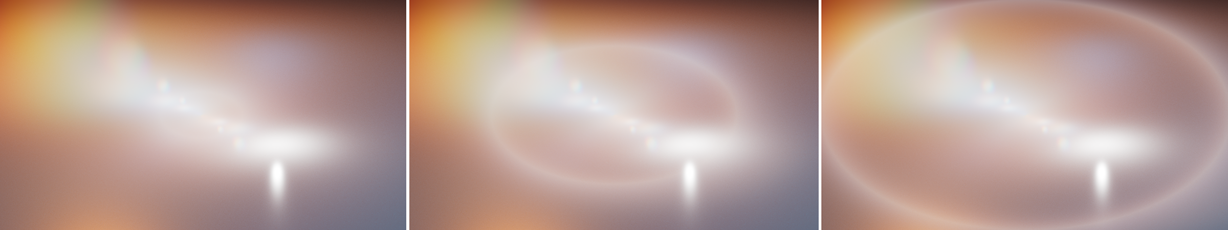
Halo
A Halo is an additional, circular or elliptical glow effect that can be added to the Flare overlay. Increasing the value will scale the Halo up. A Halo is always centered in the view and adapts to the aspect ratio of the render resolution.
|
|
From left to right, using a 'Halo' of 10%, 30% and 50%.
|
Tint
By default, the Flares takes over the coloring of the bright areas of the image that triggered the effect or get some Chromatic coloring. However, by activating this option you can also assign your own colors, like up to five, to color the Flares individually. Tint 1 colors the first and Tint 5 the last Flare. The Halo is not colored by the Tint effect.
By entering dark colors, you can also use the Tint feature to remove some of the Flares from the rendering.
1/2/3/4/5
If Tint is active, you can use these to color the Blooming effect from its bright center (1) to the outer radius (5).
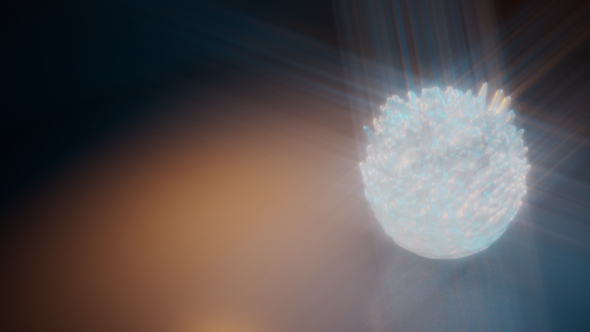
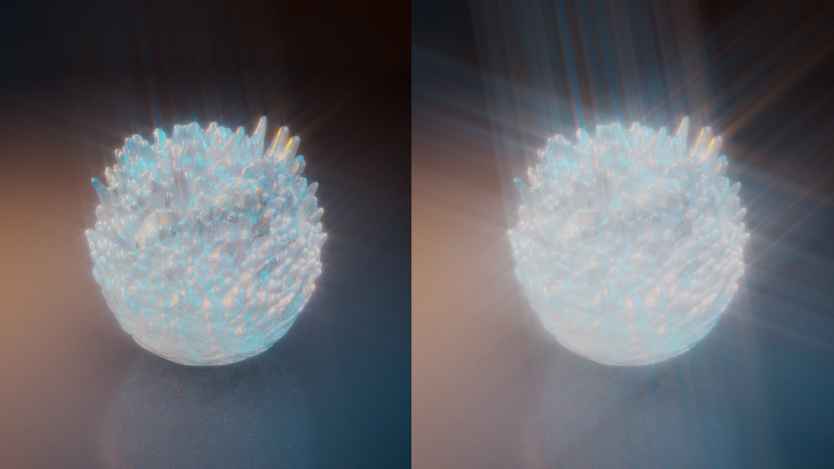
Streak
The finest scratches or disturbances in the surface of the front lens can cause intense light to be scattered radially. These settings simulate this effect.
|
|
Example result of the Streak PostFX.
|
Streak
- Off: No Streak effect is created for rendering.
- Render Settings: The camera is using the global Streak settings from the Render Settings dialog. This is the default mode.
- Override: The local Streak settings from the camera dialog are used, even if the Render Settings are configured in another way.
Intensity
Use this value to set the opacity of the Streak rendering.
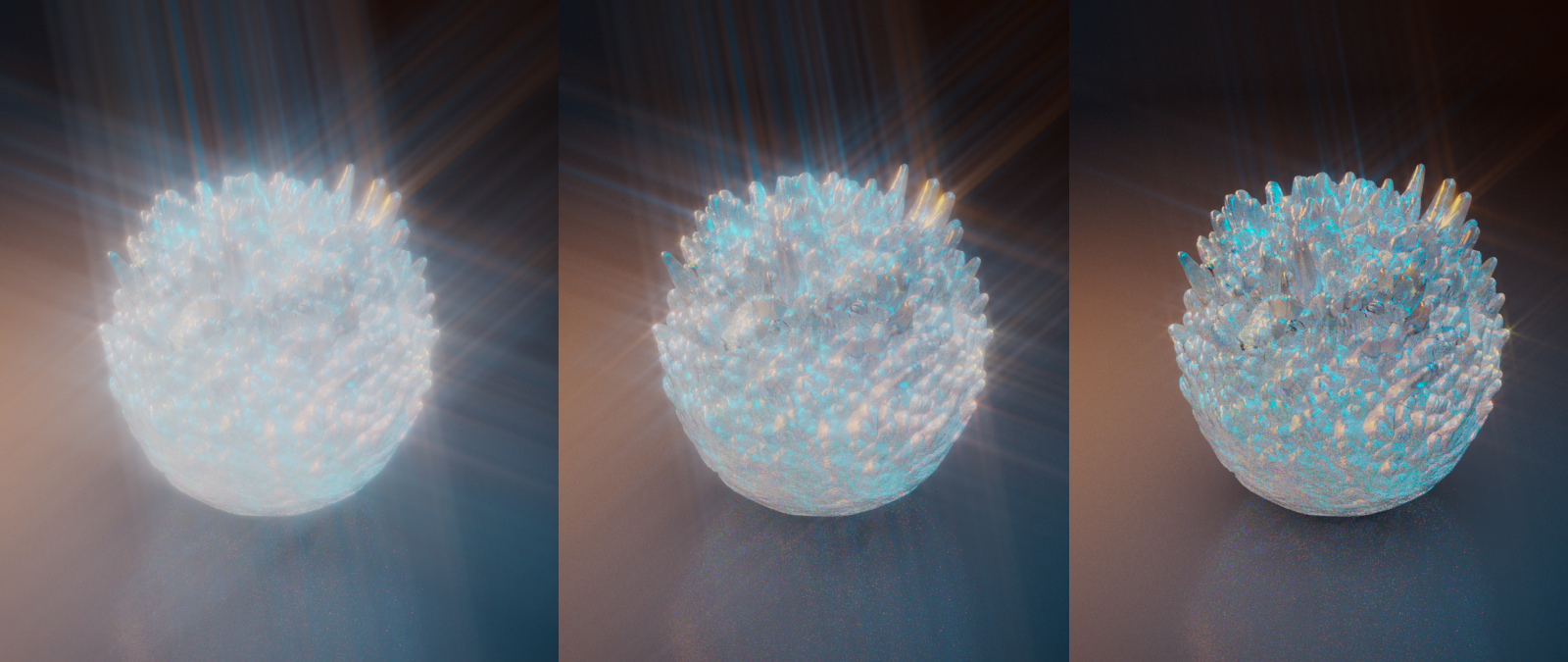
Threshold
This value determines which pixel brightness must be reached for Streaks to occur. Smaller values mean that even lower brightnesses are sufficient to contribute to the calculation of Streaks.
|
|
From left to right, examples of Streak rendering with a Threshold of 1, 3 and 10.
|
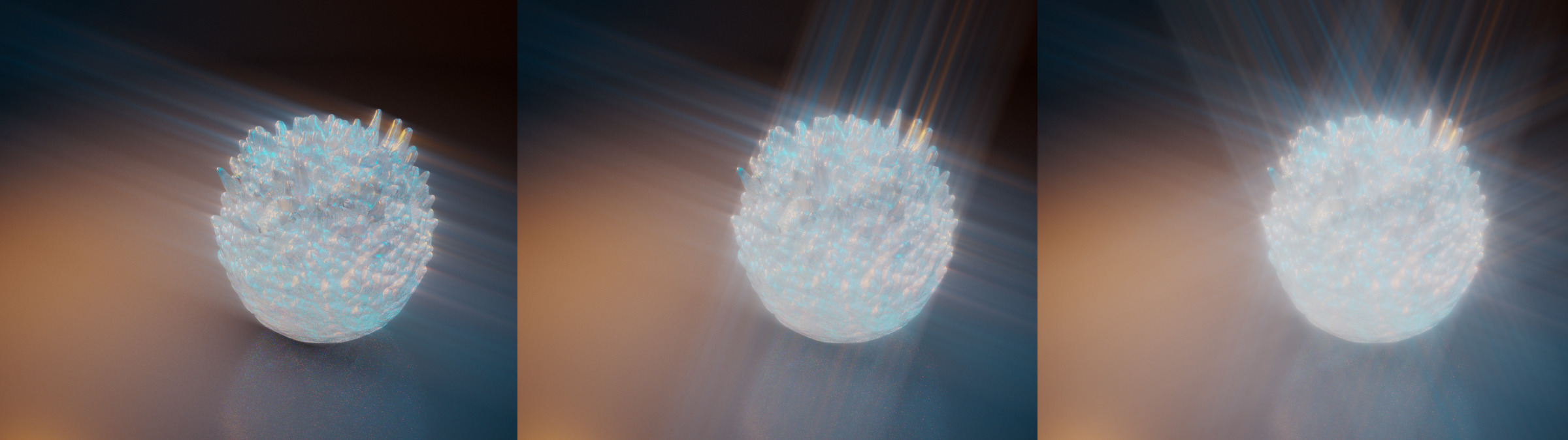
Tail
This value sets the length of the light rays of the Streak effect.
|
|
The rendering on the left uses a Trail value of 0.7. The right rendering is using a value of 1.
|
Softness
This parameter can be used to blur the Streaks.
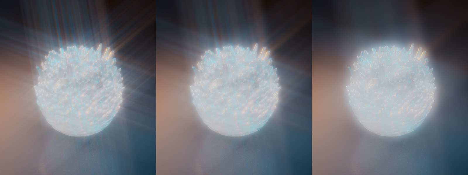
|
|
A variation of Softness values, starting on the left with a Softness 0 %, a Softness of 20 % in the middle and a value of 50% for Softness on the right.
|
Number
This sets the number of directions used to draw the Streaks.
|
|
From left to right, using a number of 1, 2 and 4 Streaks.
|
Angle
Use this value to change the direction of the streaks.
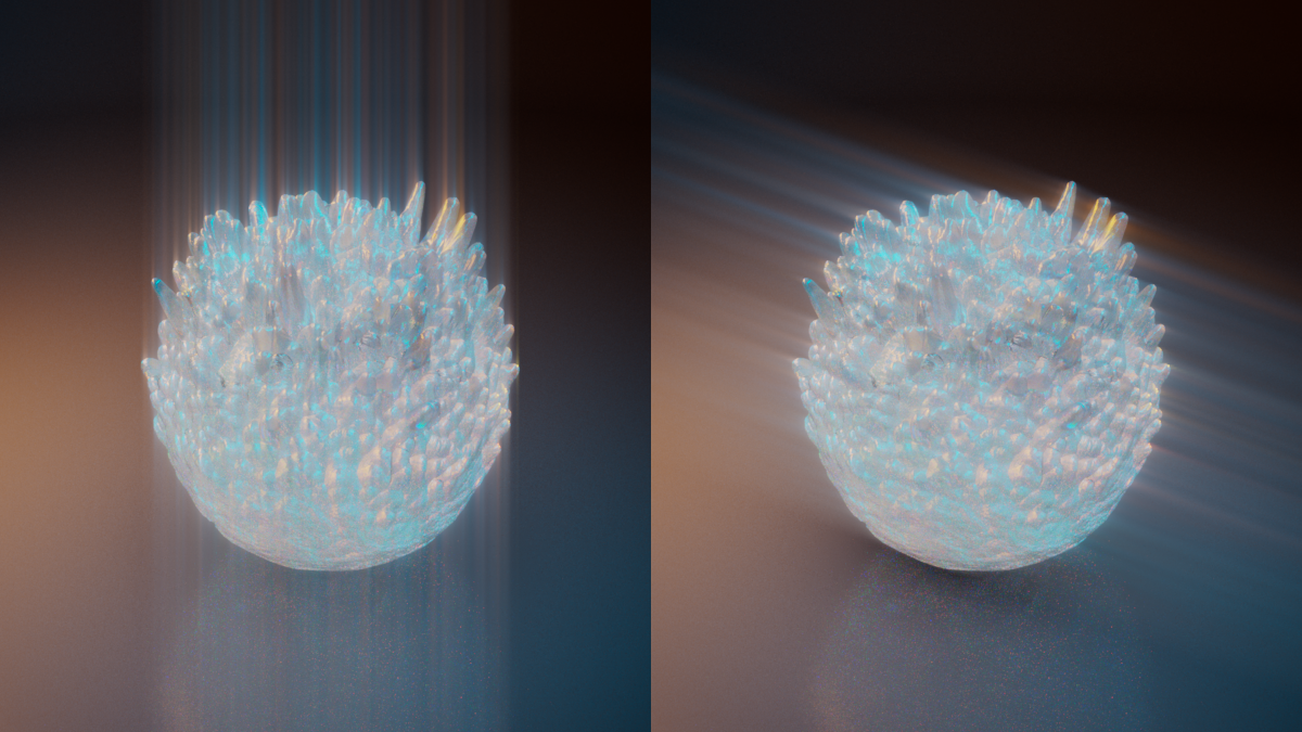
|
|
The left rendering use an Angle of 90°, the right shows an Angle of 20°.
|
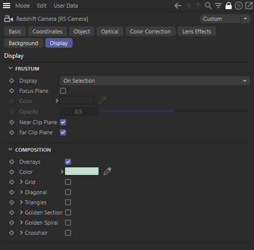
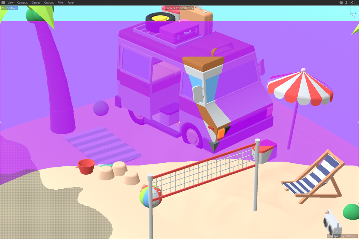
Display
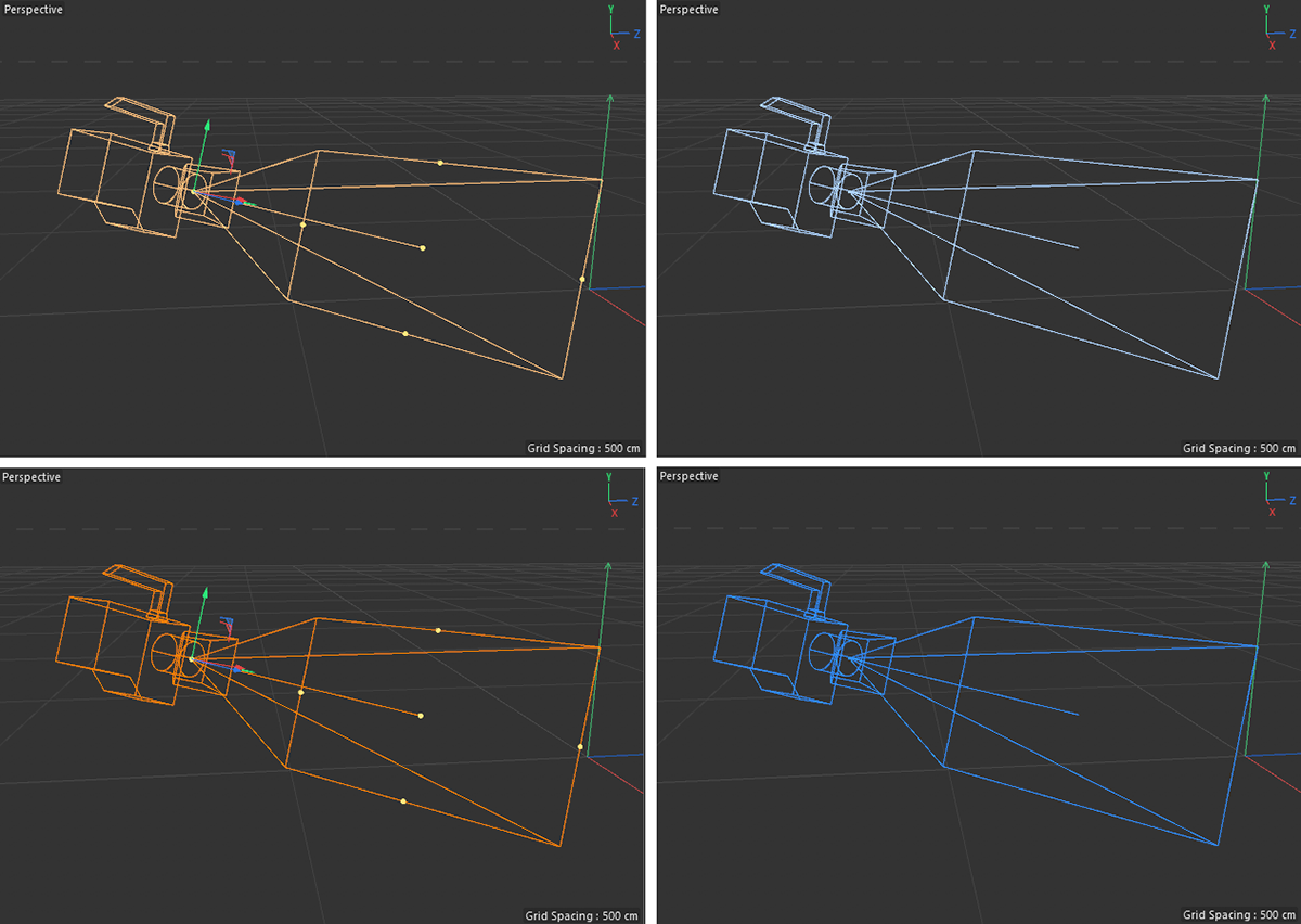
This section contains display options and help elements of the camera. The Redshift camera is displayed as an icon in the viewports and colored differently depending on its state:
- Bright orange hue: The camera is selected, but is not activated as a render camera
- Dark orange hue: The camera is selected and has been activated as a render camera
- Light blue hue: The camera is not selected and has not been activated as a render camera
- Dark blue tint: The camera is selected and has been activated as a render camera
|
|
The different states of the camera object are represented by colors in the viewports.
|
Frustrum
Display
The camera display consists of at least two elements: the display of a camera icon and a view pyramid, through which the camera's aperture angles and focus distance are displayed.
The symbol of the camera is always drawn to the viewports, if the Viewport Visibility of the camera object is positive.
The viewing pyramid giving the opening angles of the camera is an optional display element in the viewports and can be configured using these options:
- Off: No viewing pyramid is drawn at any time.
- On Selection: The viewing pyramid is only drawn if the camera object is selected.
- On: The display of the viewing pyramid is always visible in the viewport.
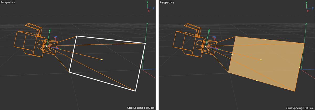
Focus Plane
In the Optical settings of the camera you're able to set a Focus Distance which can be used to control Bokeh rendering. This distance is also represented by the frame at the base of the viewing pyramid, which is highlighted in white on the left of the following image.
To emphasize this Focus Plane, it can be activated to be displayed as a solid colored plane in the viewports.
|
|
The left side shows the camera's focal plane with an additional white border for clarity. The right side of the figure shows the activated display of a Focus Plane.
|
Color
This sets the color of the Focus Plane, if it has been activated for display.
Opacity
If the Focus Plane is activated, this value sets the opacity of the display in the viewports.
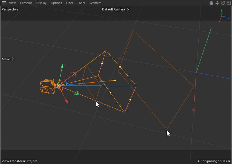
Near Clip Plane
Far Clip Plane
Within the Object settings of the camera, two clipping distances can be activated and set, to prevent the camera from always rendering everything within its field of view. Using these options will add frames to the viewport, representing the different Depth settings for the clipping planes.
|
|
If the near or far clipping planes have been activated, their distances can be visualized by additional frames as highlighted by the cursor symbols in the image above.
|
Composition
Here you will find settings that, when enabled, will display guidelines in the Viewport that you can use to arrange your scene.
- These Helpers are only visible in the Viewport for which the camera is defined.
- These Helpers will be adjusted to fit within the Render Safe region.
- These Helpers will normally be invisible when the scene is rendered (unless the Viewport renderer make an exception).
This does not mean that all objects in your Project must be arranged according to these Helpers (which in most cases is not useful) but it can often help arrange a distinctive object or objects along a visual line or lines (this can be done by either repositioning the object(s) or by simply zooming or repositioning the camera accordingly). Repositioning the camera can often achieve a more subtle effect.
The various options can be combined.
Overlays
Enables or disables the visibility of the Helpers for the active camera. The following Helper types are available.
The different settings and options for Composition Helpers are identical to the options available at a standard Cinema 4D camera. You can learn more about them here.
- Color
- Grid
- Diagonal
- Triangles
- Golden Section
- Golden Spiral
- Crosshair
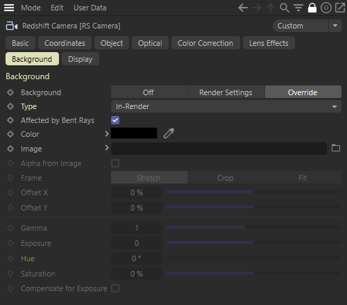
Background
Background
- Off: Background is disabled for rendering.
- Render Settings: The camera uses the global Background settings from the Render Settings dialog. This is the default mode.
- Override: The local Background settings from the camera dialog are used, even if the Render Settings are configured in another way.
Type
This setting determines when the color or background image is applied when rendering - critically, it controls if the background is color corrected or takes part in effects such as depth of field.
-
In-Render: The background is used during object rendering and is therefore subject to all the same lens effects - essentially this is the same as if you were to render an image plane in the scene at infinite distance. The background will be affected by anti-alising, bent rays for refractive materials, depth of field and all the same exposure and color correction settings as the other 3D objects in the scene.
-
Pre-Composite: The background is applied after the rendering is complete but before the post effects are calculated. In this way, a background image can still influence the calculation of bloom or flare effects, for example, but will exclude the background image from anti-alisasing and bent rays for refractive materials and depth of field.
-
Post-Composite: The background is applied only after scene rendering and post effects have been calculated. Camera level exposure, color corrections, and all other post effects do not affect the background image.
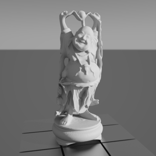
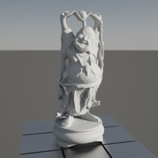
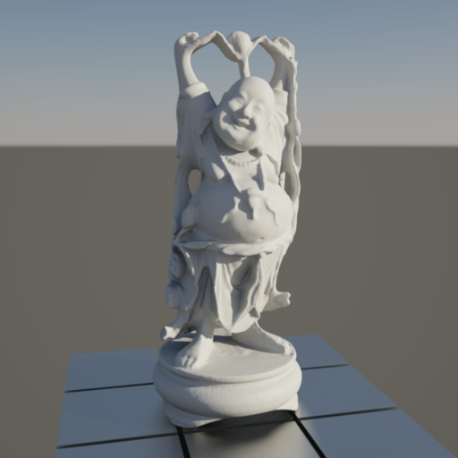
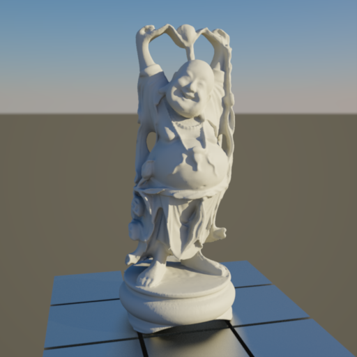
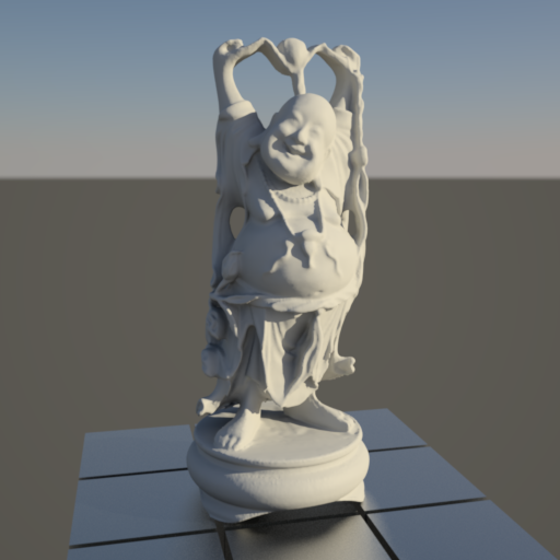
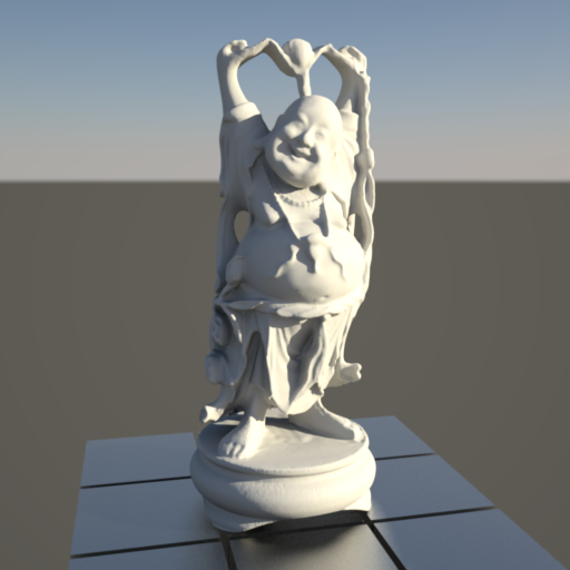
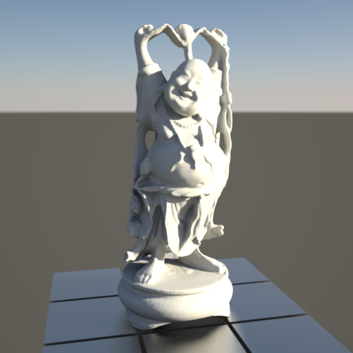
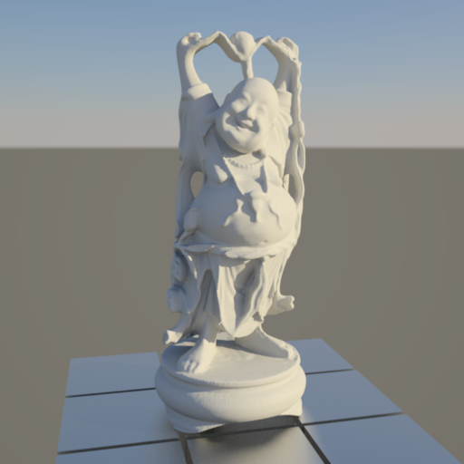
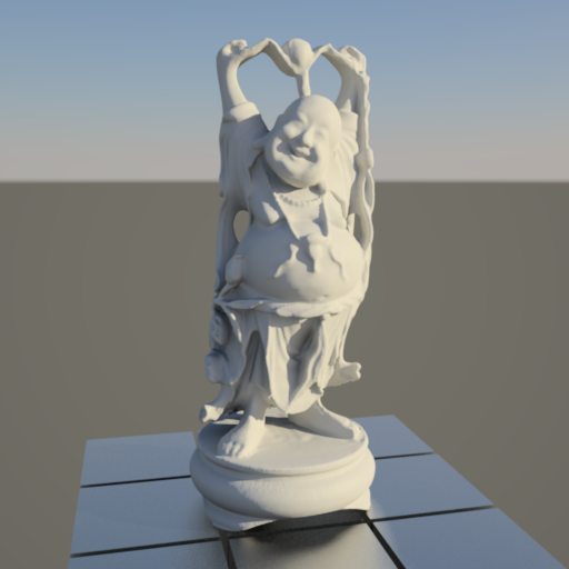
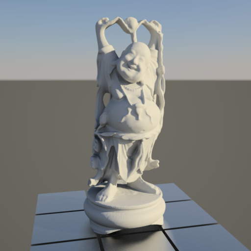
In the example images below take note that while the In-Render and Pre-Composite types can look very similar, only In-Render is affected by depth of field and transmissive materials. All the while, Post-Composite is not affected by any camera effects.
Affected by Bent Rays
Only relevant when In-Render background type is used.
When enabled, the background is rendered like a normal 3D object in the scene and is therefore also subject to changes, e.g. when viewed through a refractive/transmissive object or when rendered with depth of field. When disabled, the background is not affected by these effects but is still subject to changes to exposure and color correction.
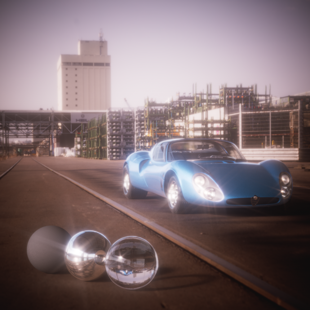
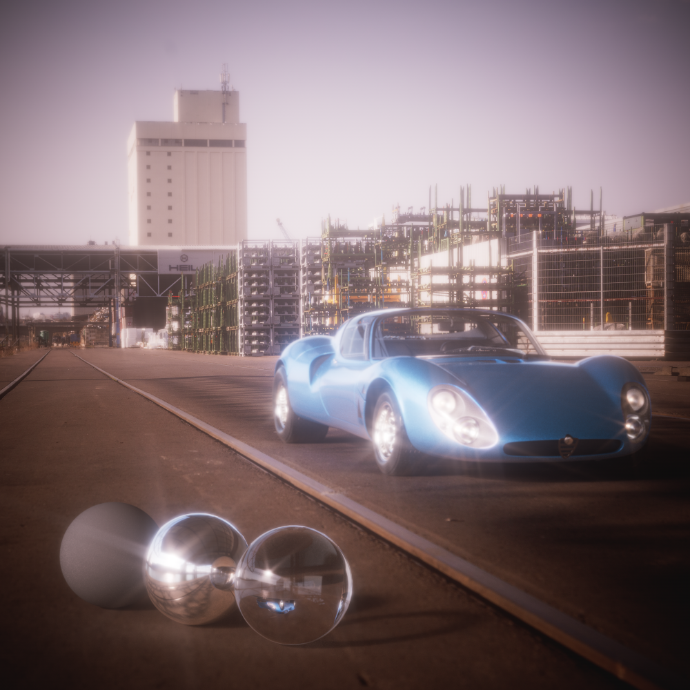
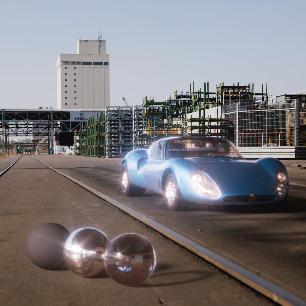
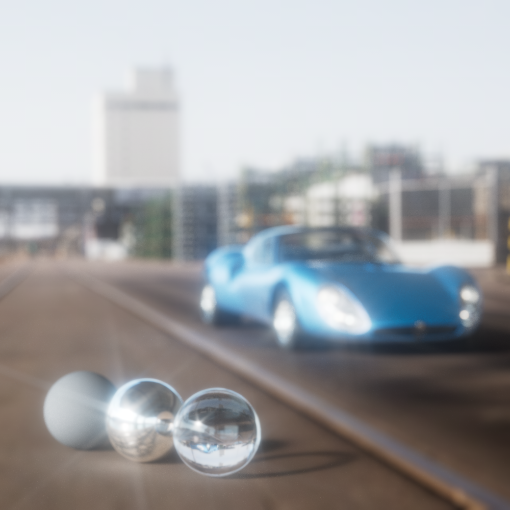
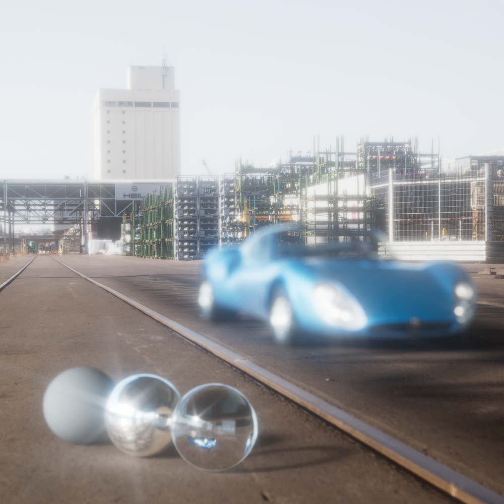
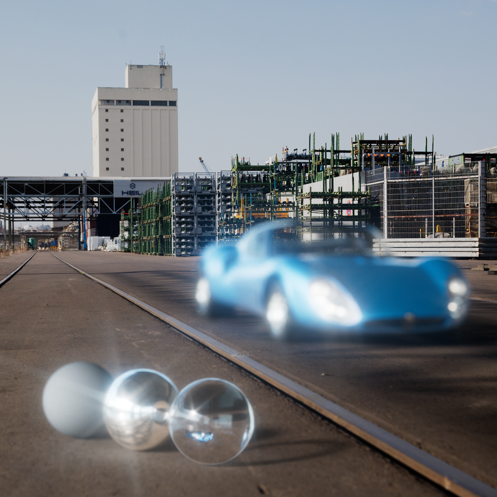
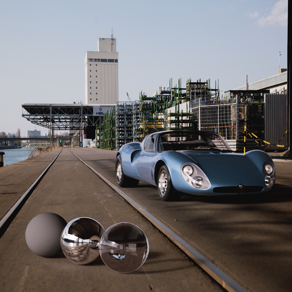
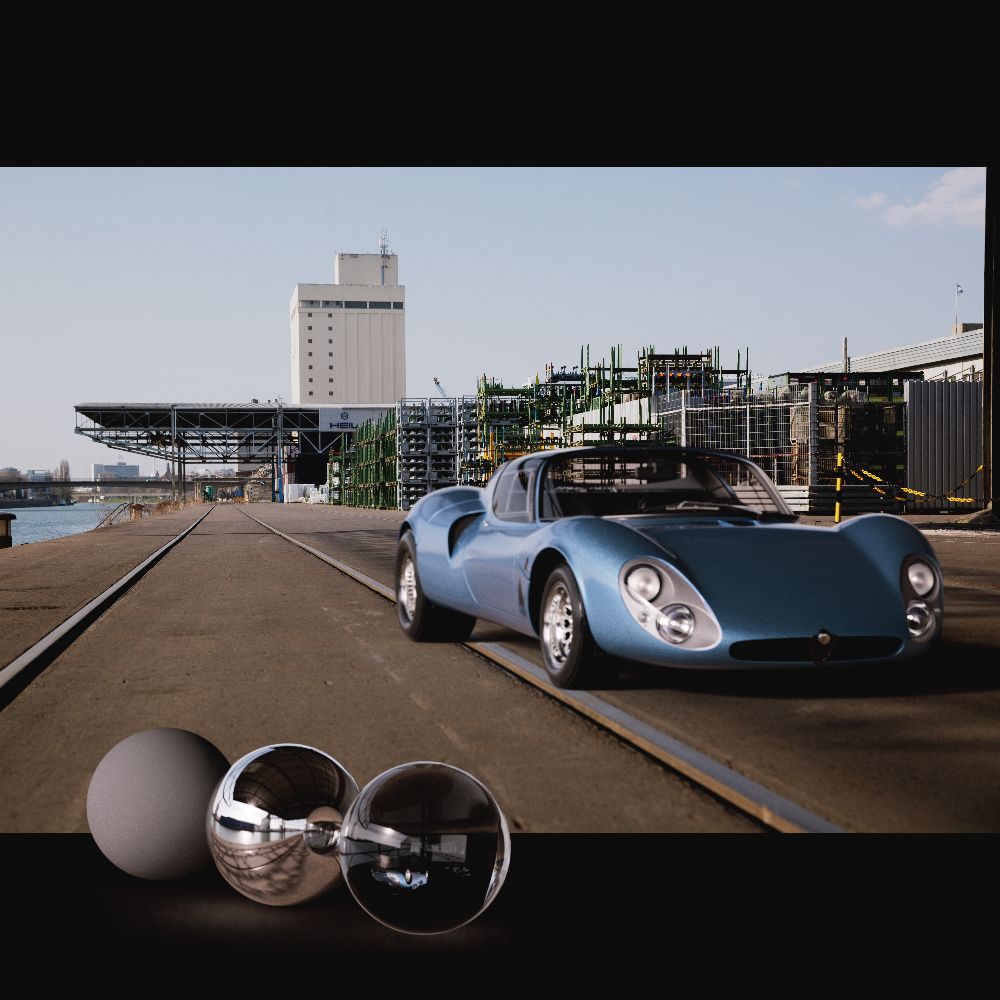
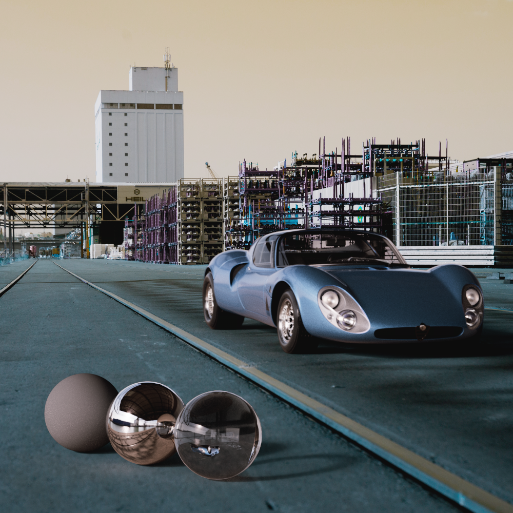
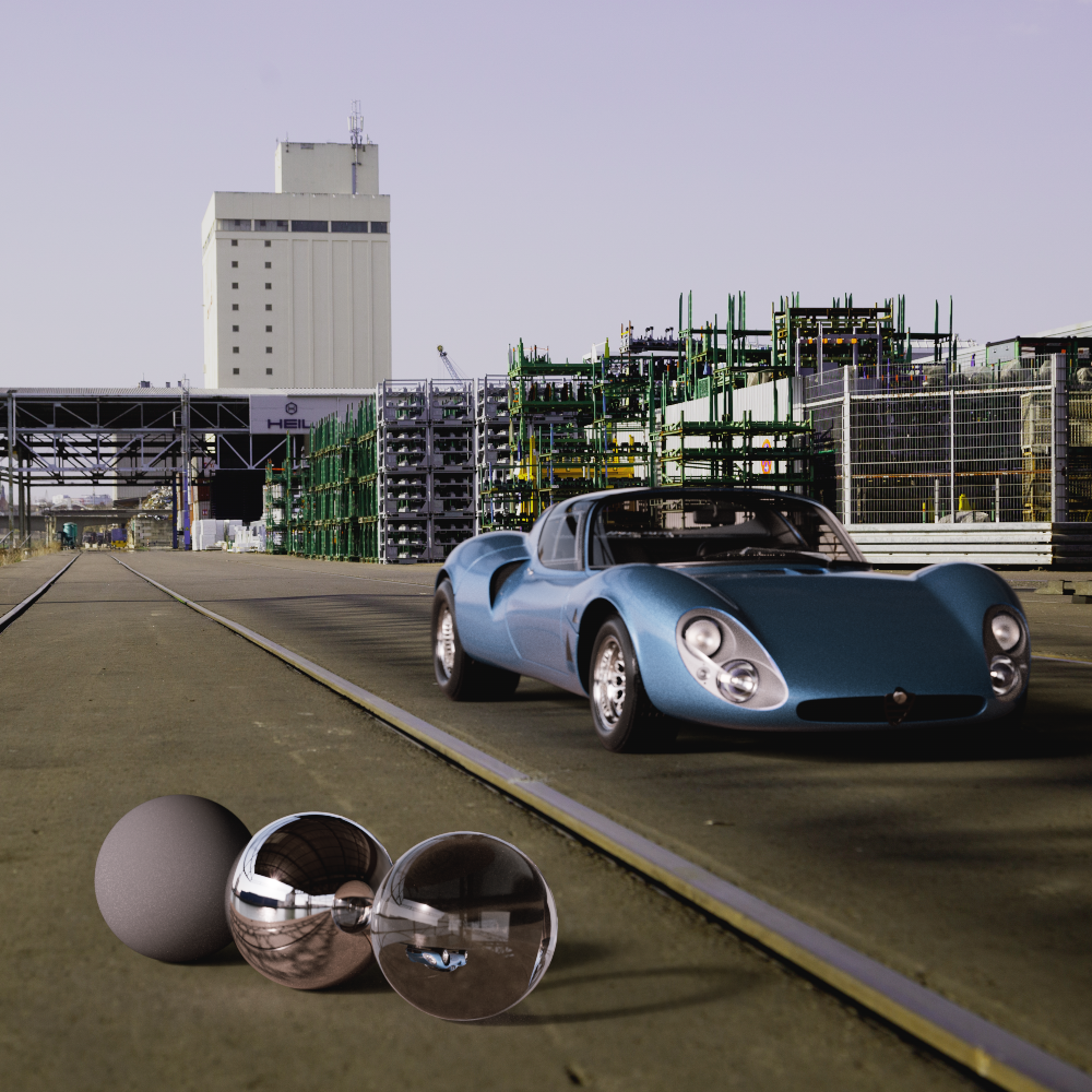
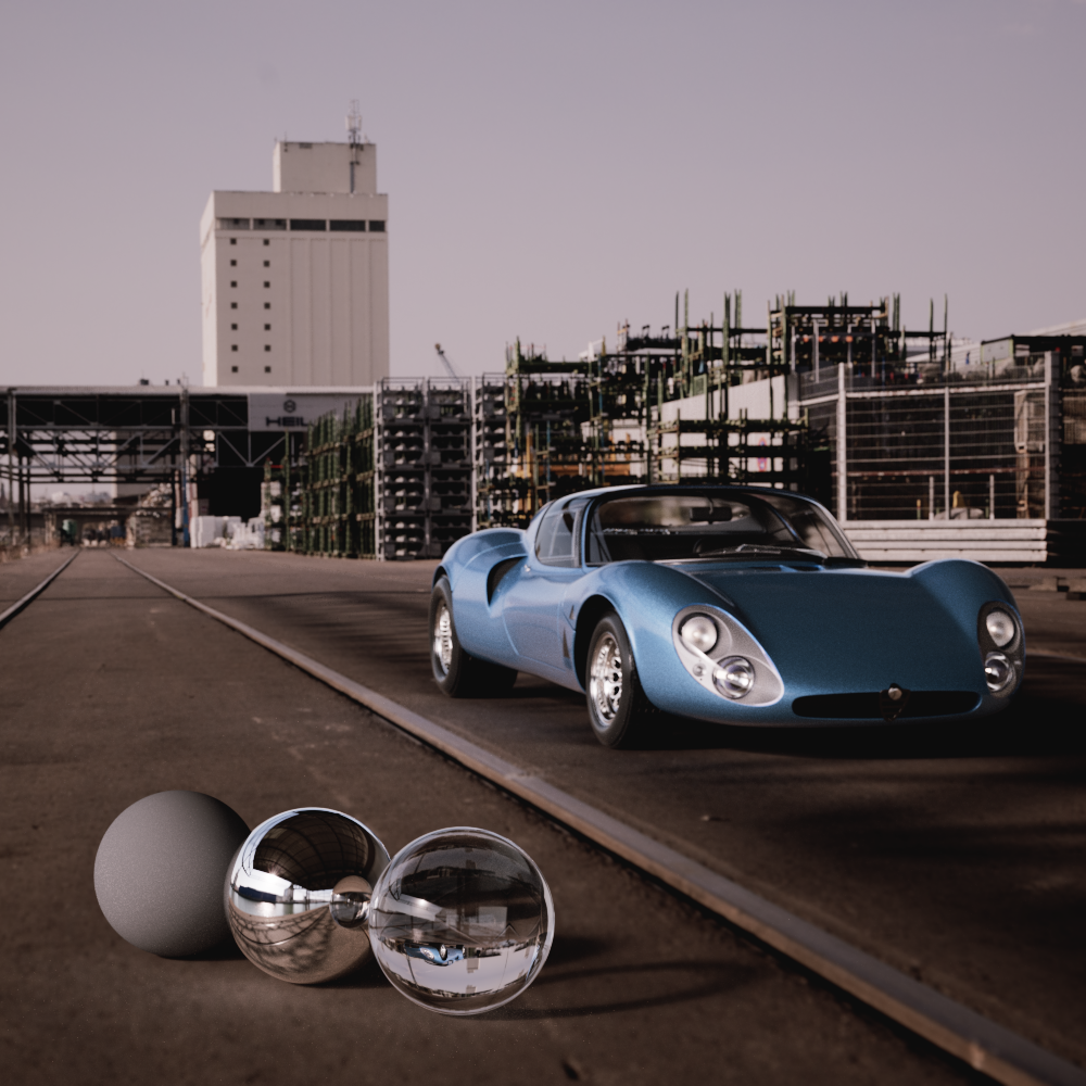
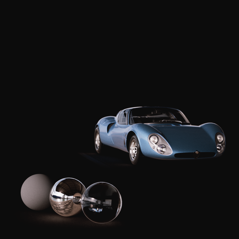
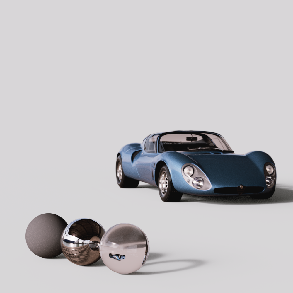
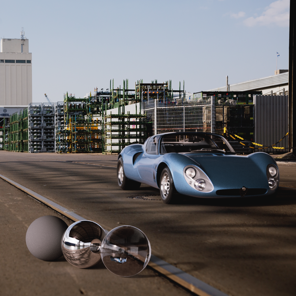
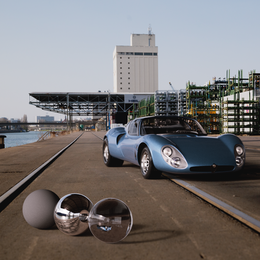
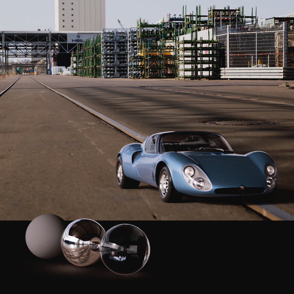
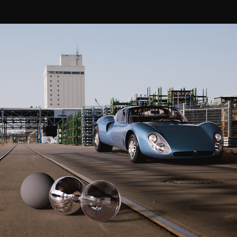
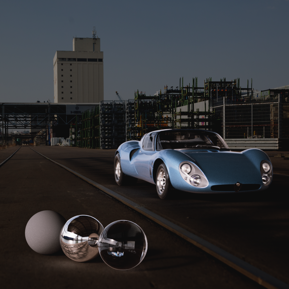
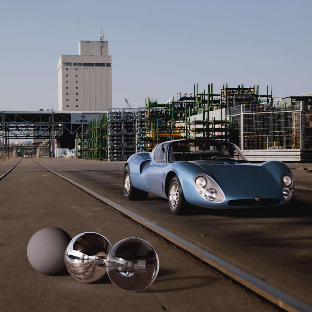
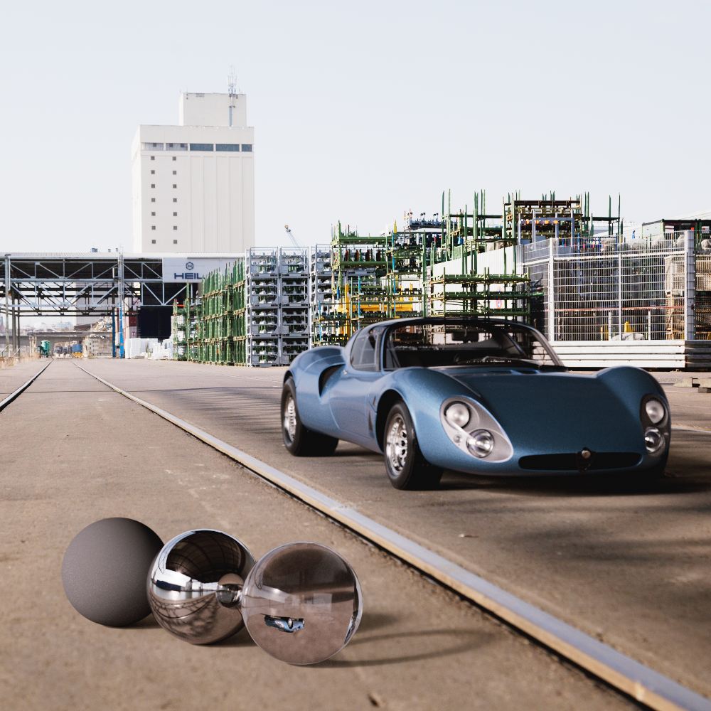
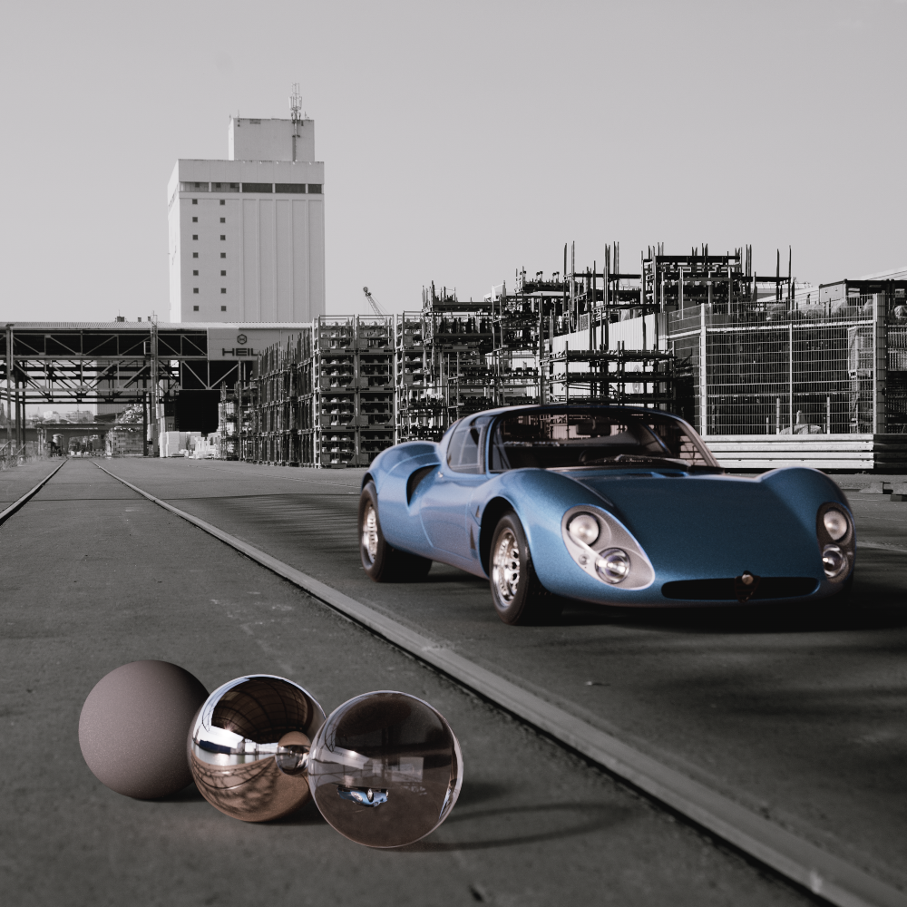
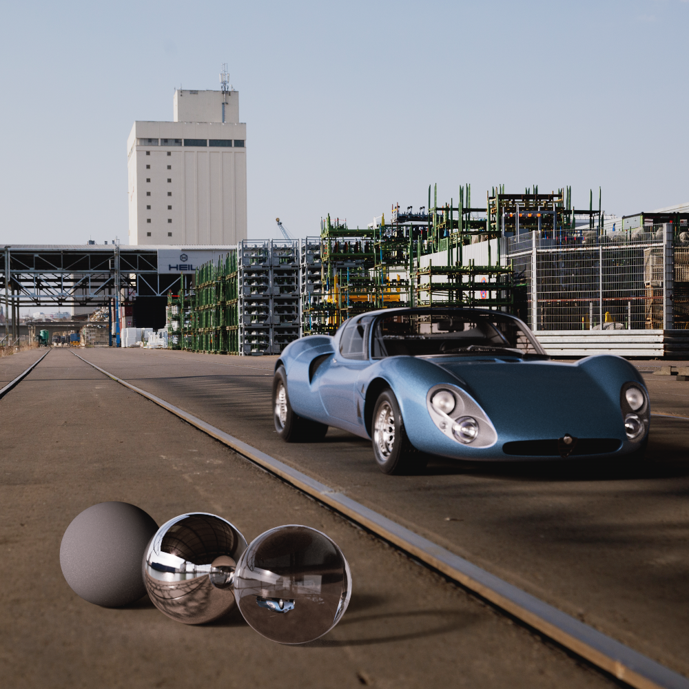
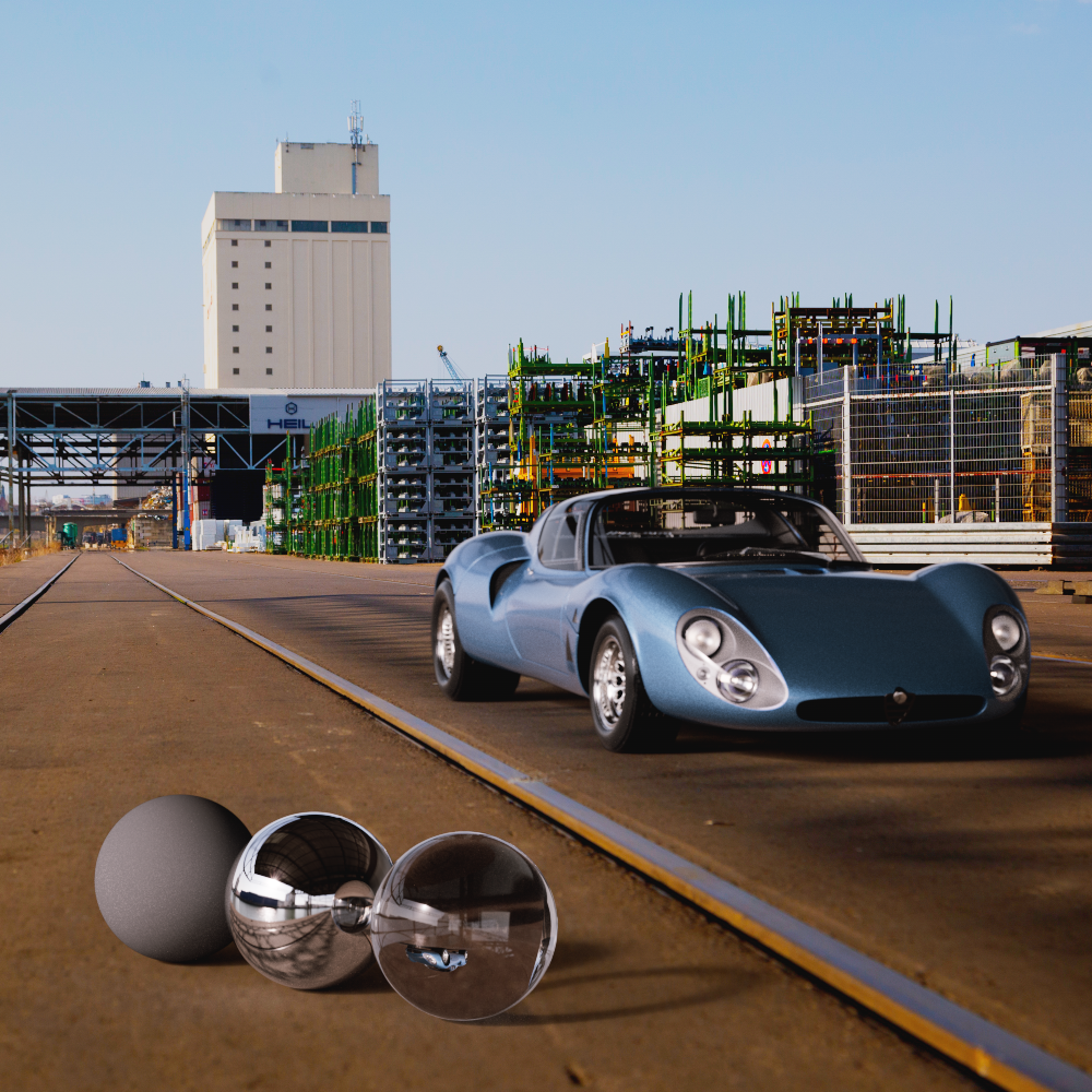
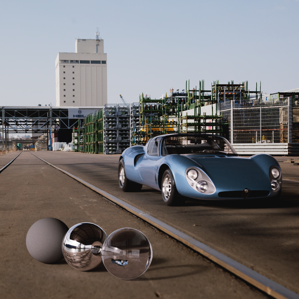
In the example images below notice how the background is bent by the transmissive glass sphere and car windows or blurred by depth of field when enabled. By comparison, the background is completely clear and the rays are not bent by transmissive objects when disabled, instead they pass right through and only the actual 3D scene is affected by these types of effects.
|
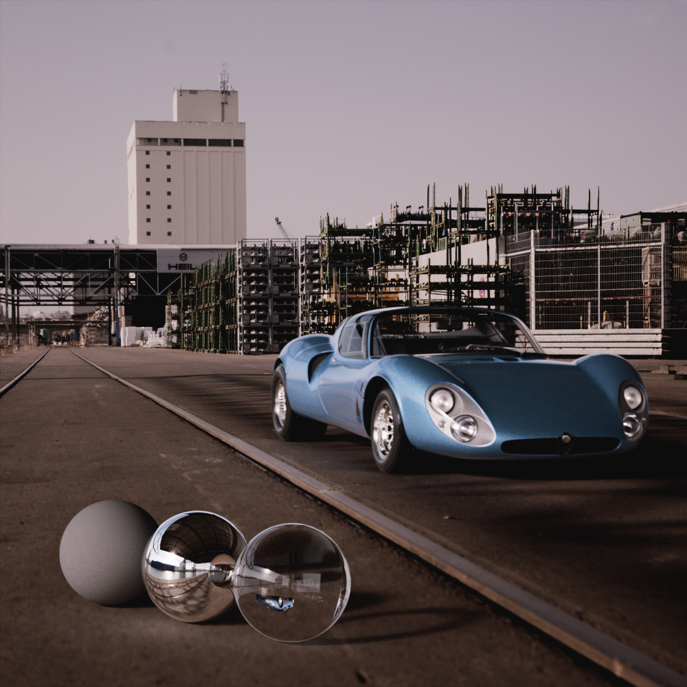
|
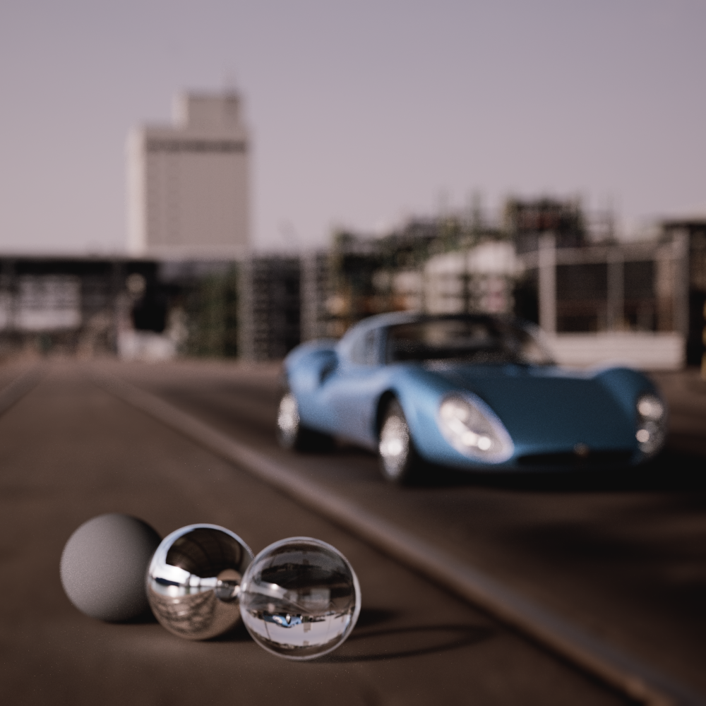
|
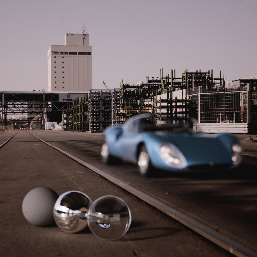
|
Affected by Bent Rays:
Enabled (default) |
Disabled |
Enabled (default) |
Disabled |
Color
This is the plain color used in the background of the rendering. The background color is overridden when a background image is loaded.
|
|

|
| Background Color: Black (default) |
White |
Image |
Alpha
Controls the alpha channel output for the background.
Image
An image loaded here replaces or covers the solid Color of the background. The background color may still be visible in the render if the background image does not cover the entire framebuffer (see Frame or Offset parameters) or if the loaded Image has an alpha channel.
Color Space
Controls how the colors of the background image are interpreted. In general low dynamic range images like PNG and JPG should use the sRGB color space and high dynamic range images should use the scene-linear Rec709-sRGB color space. If you know your background image should use a different color space then use that. For more information please see the Color Management section.
Alpha from Image
When enabled the alpha channel from the loaded background image is used for alpha output in renders. When enabled and using Pre and Post-Composite modes with a background image that does not have an alpha channel the background will be rendered out with the alpha channel set to 0.
When disabled the render will have no alpha output from the background.
Frame
If you have loaded an Image for the background, this setting adjusts the scaling of the image in the rendering. This is only relevant if the width to height ratio of the image does not match the aspect ratio of the rendering:
-
Stretch: The width and height of the Image are changed to match the aspect ratio of the renderings. The background image will cover the entire background in any case, however, the image will be distorted if it doesn't have the same aspect ratio as the render.
-
Crop:The background image is scaled evenly to fit the longest side of the rendering. For portrait rendering, this is therefore the height of the rendering, and for landscape rendering, it is the width. The image portion along the shorter side may overhang the rendering and will therefore be truncated for the rendering.
-
Fit: The background image is scaled evenly to fit the shortest side of the rendering. This always leaves the entire background image visible in the rendering, but there may be areas that are not covered by the image. The plain background color is then displayed there.
Offset X
Allows you to move the background Image horizontally. In the areas that become free as a result, the plain background color becomes visible.
|

|
|
| Offset X: -20 |
0 (default) |
20 |
Offset Y
Allows you to move the background Image vertically. In the areas that become free as a result, the plain background color becomes visible.
|

|
|
| Offset Y: -25 |
0 (default) |
10 |
Gamma
Changing the Gamma value lightens or darkens only the midtones, without significantly affecting the highlights and depths. This means: Black remains black even after a Gamma change, white remains white.
Exposure
All brightnesses of the loaded Image can be raised or lowered evenly.
|
|
|
| Exposure: -2 |
0 (default) |
2 |
Hue
This allows all color values of the loaded Image to be shifted evenly. The basis for this is a color ring on which all colors are applied. The color shift can then be specified via an angle between 0° and 360°. For this reason, a color shift of 360° also shows the original color values again.
Saturation
Use this value to decrease or increase the color saturation of the loaded background Image.
|
|
|
| Saturation: -100 |
0 (default) |
100 |
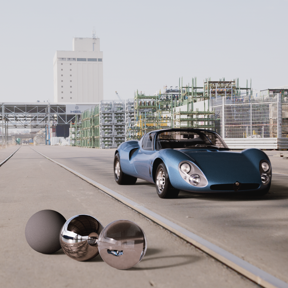
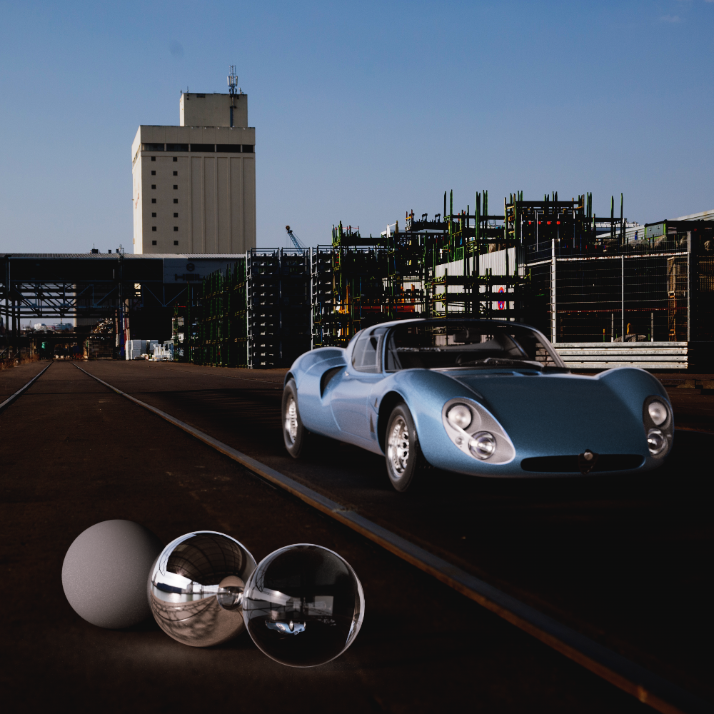
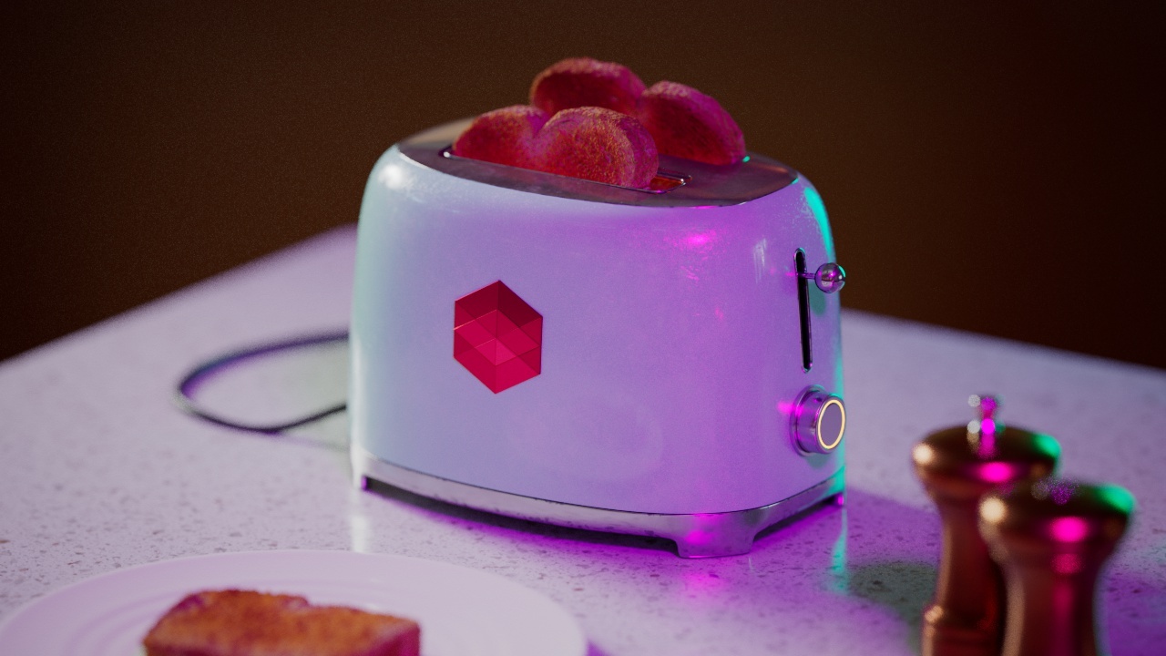
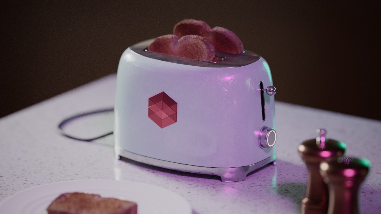
Compensate for Exposure
When disabled, the loaded background image will be affected by the camera's Exposure settings.

|
|
Compensate for Exposure:
Disabled (default) |
Enabled |