Table Of Contents
Introduction
Tessellation is a computer graphics technique that can make a coarse, low-polygon mesh render smooth. This is achieved through polygonal subdivision, which happens at render-time. Working with low-polygon meshes and letting Redshift do the subdivision during rendering has certain advantages:
- Low-polygon meshes can be simpler to manage for animation reasons
- The 3D program itself doesn't have to maintain large numbers of polygons which can be expensive in terms of system memory
It can be more memory-efficient (which is important for GPUs) when combined with view-dependent and/or adaptive subdivision. Small or distant objects, for example, can render smooth with fewer subdivisions.
Redshift subdivides quad polygons using the Catmull-Clark algorithm. For triangles, it uses the Loop algorithm. Redshift supports both screen-space and world-space adaptive tessellation for improved memory usage.
Displacement is a technique typically combined with tessellation. It allows the user to add extra detail on their meshes through shader networks, i.e. textures, noise shader nodes, etc.
The benefits of displacement include:
- Manipulating textures and shader networks for certain displacement effects (such as a brick wall) is much easier than manipulating lots of vertices in a 3D program
- Sculpting apps like ZBrush and Mudbox are easier to use compared to polygon modeling when creating organic geometry. A displacement (or vector displacement) map allows this sculpted detail to be applied on a fairly low-resolution mesh.
Because displacement can happen on adaptively tessellated meshes, it can be more memory efficient than using a full-detail, full-tessellation mesh in memory at all times and irrespective of its size or viewpoint.
Redshift supports both heightfield (displacing along the vertex normal) and vector displacement maps. The vector displacement maps can be in object or tangent space. Importantly, any displacement detail that couldn't be represented given the existing tessellation settings is represented, instead, using bump mapping – therefore a good level of surface detail can be present even in fairly low-quality tessellation settings.
How To Enable
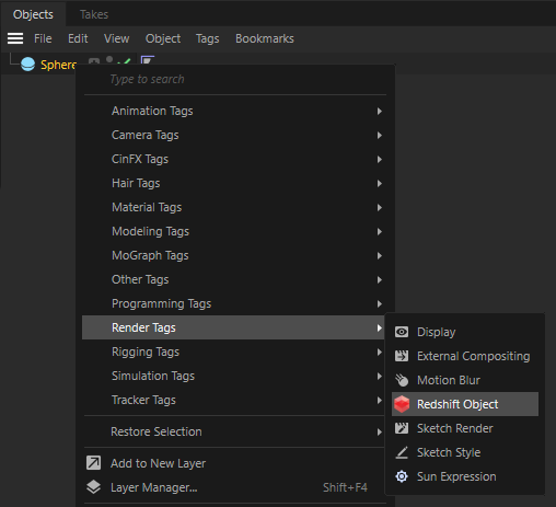
The object Tessellation and Displacement options are part of the Redshift Object Tag. In the scene tree, right-click on the desired object and select the Redshift Object tag from the Render Tags category.
After selecting the tag, and navigate to the Geometry tab. To activate the settings check the Override option.

The Tessellation and Displacement settings are effective on the object that hosts the Redshift Object tag as well as any child objects.
Tessellation Settings
Subdivision Rule
Redshift supports two different algorithms for polygon subdivision: "Loop", which is used for triangles and "Catmull-Clark", which is used for quads. These algorithms are also called "Subdivision Rules".
The "CC+Loop" subdivision rule uses Catmull-Clark for quads and Loop for triangles. On the other hand, the "CC Only" option uses Catmull-Clark for triangles too, by first splitting each triangle into three quads. The "CC Only" mode should be used when Redshift is combined with other software that doesn't support Loop subdivision.
Screen Space Adaptive
Enabling screen-space adaptive tessellation means that objects that are further away from the camera will be subdivided less and will, therefore, use fewer polygons and less GPU memory. If this option is disabled, then subdivision becomes "world space adaptive". This option affects the unit used for the "minimum edge length" setting, as explained below.
Smooth Subdivision
This controls whether Redshift should subdivide quads and triangles using the Catmull-Clark and Loop algorithms respectively or whether it should do a simple linear subdivision instead. If you are adding displacement on simple angular meshes (such as walls or a box) and don't want them turned into smooth, curvy objects, disabling smooth subdivision might be the right option for you.
|
|
|
|
Smooth subdivision enabled |
Smooth subdivision disabled |

Minimum Edge Length
Adaptive subdivision keeps dividing quads/triangles while their edges are longer than this setting. If you are using screen-space adaptive subdivision, this length is measured in screen pixels. If you are not using screen-space adaptive subdivision, this means "world space adaptive subdivision" so the length is measured in world-space units. The smaller this value, the more tessellation will be applied to the mesh. If you set the value to zero, tessellation will continue until "maximum subdivisions" (see below) has been reached.
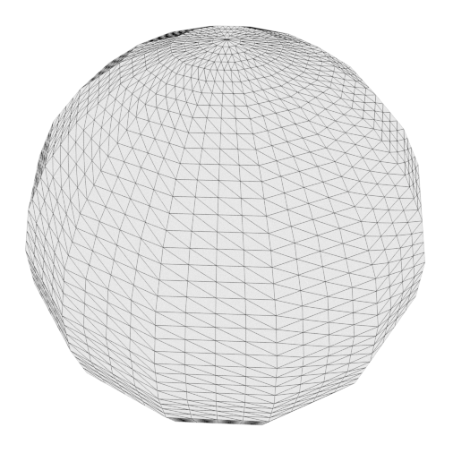
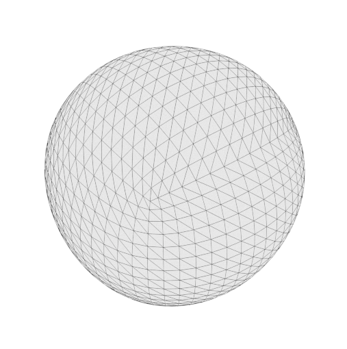
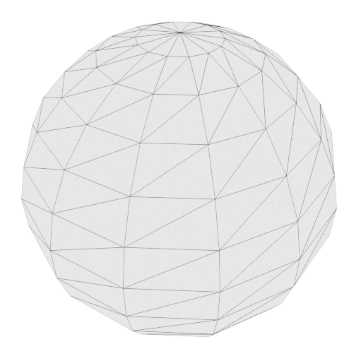
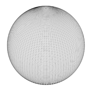
The following pictures show a tessellated cube which becomes this spherical-like shape with smooth tessellation. Notice how there is more tessellation when the min edge length becomes smaller. This is showing screen-space adaptive subdivision so 8 means "8 pixels" while 2 means "2 pixels".
|
|
|
|
Screenspace adaptive with min edge length of 8.0 |
Screenspace adaptive with min edge length of 2.0 |
Maximum Subdivisions
Subdivision happens in 'passes'. Each pass can turn single quad/triangle into 4 quads/triangles respectively. This means that the number of polygons can grow extremely quickly with this option. It is a "power of four".
- A setting of 1 can turn 1 quad into 4 quads
- A setting of 2 can turn 1 quad into 16 quads
- A setting of 3 can turn 1 quad into 64 quads
- A setting of 4 can turn 1 quad into 256 quads
- A setting of 5 can turn 1 quad into 1024 quads
- A setting of 6 can turn 1 quad into 4096 quads
- A setting of 7 can turn 1 quad into 16384 quads
- A setting of 8 can turn 1 quad into 65536 quads
So a mesh containing only 1000 quads, using a "minimum edge length" of 0.0 and a "maximum subdivisions" 8, could become a 65 million quad mesh
![]() which could take a long time to generate and would consume lots of memory! For this reason, great care has to be applied when adjusting both "maximum subdivisions" and "minimum edge length".
which could take a long time to generate and would consume lots of memory! For this reason, great care has to be applied when adjusting both "maximum subdivisions" and "minimum edge length".
|
|
|
|
|
| Subdivision disabled | One Level | Two Levels | Three Levels |


Out-Of-Frustum Tessellation Factor
This option allows objects that are outside the camera frustum (i.e. objects that are not directly visible to the camera) to be tessellated to a lesser degree. The larger the factor, the lesser this out-of-frustum tessellation will be. This setting can help save memory by tessellating "unimportant" objects less. However, sometimes an object might be outside the camera frustum but still very visible through reflections. Or it might be casting a well-defined shadow within the camera frustum. For such objects, smaller factors should be used. A factor of 0.0 disables this optimization. For a more detailed discussion on this, please see the relevant section below.
Limit Out-Of-Frustum Tessellation / Max Out-Of-Frustum Subdivs
When "Limit Out-Of-Frustum Tessellation" is enabled, you can specify the maximum number of subdivisions that should happen outside the camera frustum with the "Max Out-Of-Frustum Subdivs" option. This setting is useful when the "Out-Of-Frustum Tessellation Factor" setting can still yield excessive tessellation. This condition can happen when the mesh is using large displacements. For a more detailed discussion on this, please see the relevant section below.
Displacement Settings
Maximum Displacement
This parameter tells Redshift what is the maximum length the displacement shaders/textures will be displacing the vertices by. For example, if you're adding two displacement textures in the shader graph and each displacement texture can push the vertices by 1 unit, then both of them can push the vertices by a maximum of 2 units, so a setting of 2.0 should be used for this setting. Unfortunately, due to flexible nature of shaders, it's not currently possible to compute this value automatically. Settings similar to this can be found on other renderers, too. They might be called "bounds padding" or "min/max bound".
If the value for this setting is set too low, you will see a 'ceiling' on your displacements, i.e. the maximum displacement will be clamped. If, on the other hand, this value is set too high, there won't be any visual artifacts but the performance could suffer. It is, therefore, advisable to use a value that is as low as possible before seeing any artifacts.
Displacement Scale
This scales the displacement results, which has the effect of accentuating or toning down the displacement. While it is possible to scale the displacement in the shader graph itself, this setting was added for the case where the same displacement shader is used on different meshes but different levels of displacement 'strength' are required among these meshes.
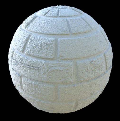
Below is a sphere displaced with a fractal shader.
|
|
|
|
|
Scale 0.05 |
Scale 0.1 |
Scale 0.3 |

Enable Auto Bump Mapping
Very high-detail surface detail can require very high tessellation levels to be captured sufficiently, otherwise the result might look too soft. However, this can mean longer rendering times and higher memory usage!
The 'Enable Auto Bump Mapping' option effectively emulates what would happen if you were to tessellate your geometry to a sub-pixel level and modifies the surface normals accordingly, as if they were bump-mapped.
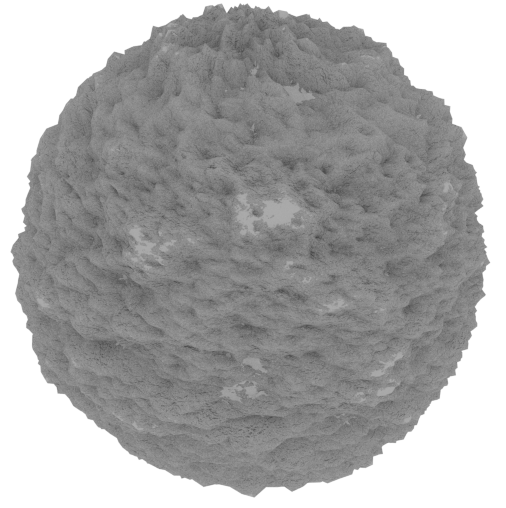
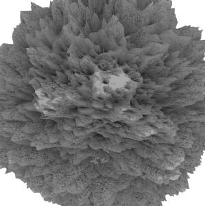
The following two spheres were rendered with exactly the same tessellation setitngs but the sphere on the right uses auto bumpmapping. Notice how it's able to capture more surface detail.
|
|
|
|
Without auto bump mapping |
With auto bump mapping |

UV Smoothing
When "Smooth subdivision" is enabled, Redshift will smooth not only the vertex positions but also the UV coordinates and tangent space vectors. Smoothing UV coordinates means that the UVs will be shifted to remove any 'zig-zagging' and 'UV breaks' during tessellation and maintain smooth UV-space curves. In the majority of cases, this is the desirable way to treat UVs. However, there are cases where strict UV layouts (such as with when UV tiles are aligned to quads) need to be preserved and not smoothed.
For this reason, Redshift supports enabling/disabling UV smoothing.
Tessellation And Instancing
When an mesh is instanced in Redshift, adaptive tessellation is no longer supported. However, you can still use fixed-rate tessellation (and, subsequently, displacement too).
To do fixed-rate tessellation you need to:
- Disable screen-space adaptive tessellation
- Set minimum edge legth to zero
- Set the maximum subdivisions to something reasonable
Please pay particular attention to the third point above, as the default setting (6 subdivisions) is too high for fixed rate subdivision. As explained above, 6 means 4096 primitives will be generated for each original primitive. So a mesh with just 1000 faces will turn into a mesh with 4 million faces!
Out Of Frustum Tessellation
The following images show what "out of frustum tessellation factor" does for polygons that are outside the camera frustum.
The test scene is simple: it's just a quad with a mild fractal displacement. The camera is looking at the quad (slightly tilted down) from a close position.
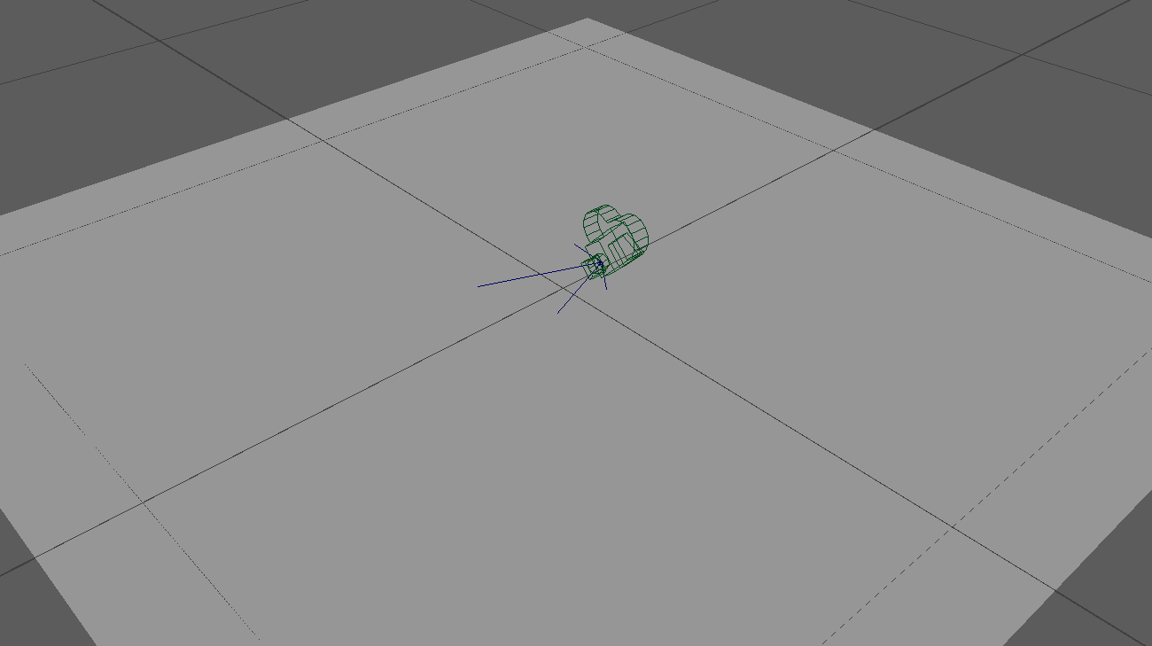
Scene setup
We use a wireframe shading node so we can visualize tessellation.
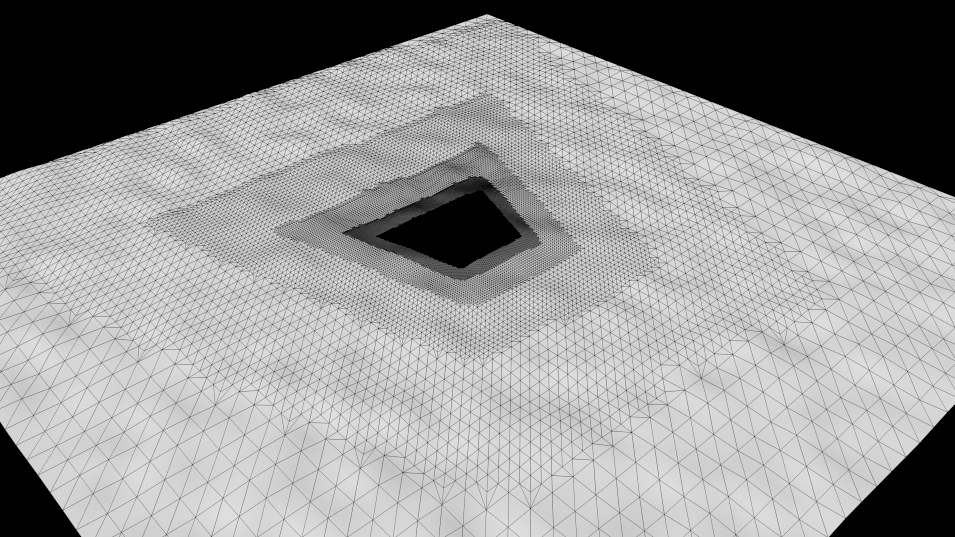
In the images below, we rendered once from the camera, then we froze tessellation in the RenderView and then we "pulled the camera back" so we could see the effect of polygon tessellation outside the camera frustum. As you can see, the polygons that are inside the camera frustum are tessellated the most. Polygons that are away from the camera frustum are tesselated less and depending on the "out-of-frustum tessellation factor". The farther away a polygon is from the camera frustum, the less it gets tessellated.
|
|
|
|
|
Out-of-frustum tessellation factor: 8 |
16 |
32 |

This setting should be used carefully! Even though a polygon is outside the camera frustum, it might be visible through a mirror or it might be casting a defined shadow inside the camera frustum! So, in these cases, making it tessellate less might make it look blocky/angular and generally too-low-poly in reflections or shadows!
While "out-of-frustum tessellation factor" allows us to get tessellation under control and save on Redshift's memory usage and rendering speed, there does exist one case where it might prove ineffective: scenes with large displacements and the camera being close to the displaced geometry.
To explain: When you set up displacement in Redshift, you have to declare a "maximum displacement" setting. This setting tells Redshift that displacement can go up to a certain distance. This setting is also used by Redshift when it tries to determine if a polygon is inside the frustum or outside it. The reasoning behind that is that, if a polygon is going to be displaced ("moved") by a lot, it might actually be moved inside the camera frustum, even though it was originally outside the camera frustum. In other words, Redshift applies "conservative" tessellation when it comes to displaced polygons that might end up being inside the camera frustum.
When this happens, Redshift might incorrectly "think" that too many polygons are inside the camera frustum and it might, therefore, tessellate these polygons a lot!
To show this, we'll edit our scene and make "max displacement" several times larger. Notice how there is much more tessellation because Redshift now thinks that all the polygons outside the frustum could possibly end up inside the frustum!
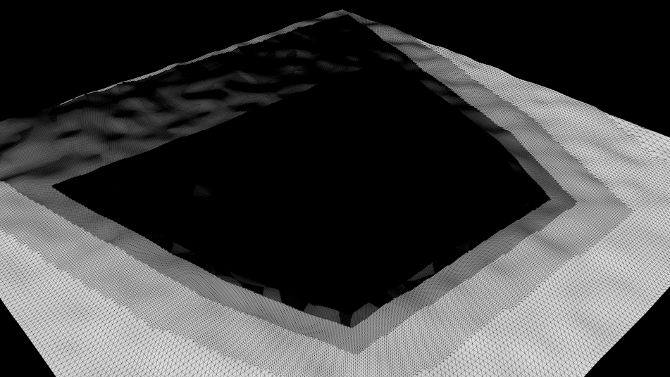
Increasing "max displacement" produces much more tessellation
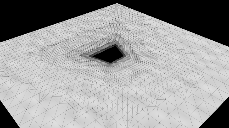
For these cases, the "Limit Out-Of-Frustum Tessellation" control should be used. In the picture below, we enabled it and set the "max out-of-frustum sudivs" to 5 (the mesh uses max subdivs 8). This means "If a polygon is outside the frustum, ensure it doesn't get subdivided more than 5 times".

Setting "max out-of-frustum subdivs" to 5 limits the tessellation
You can think of this setting as a "subdivision clamp".