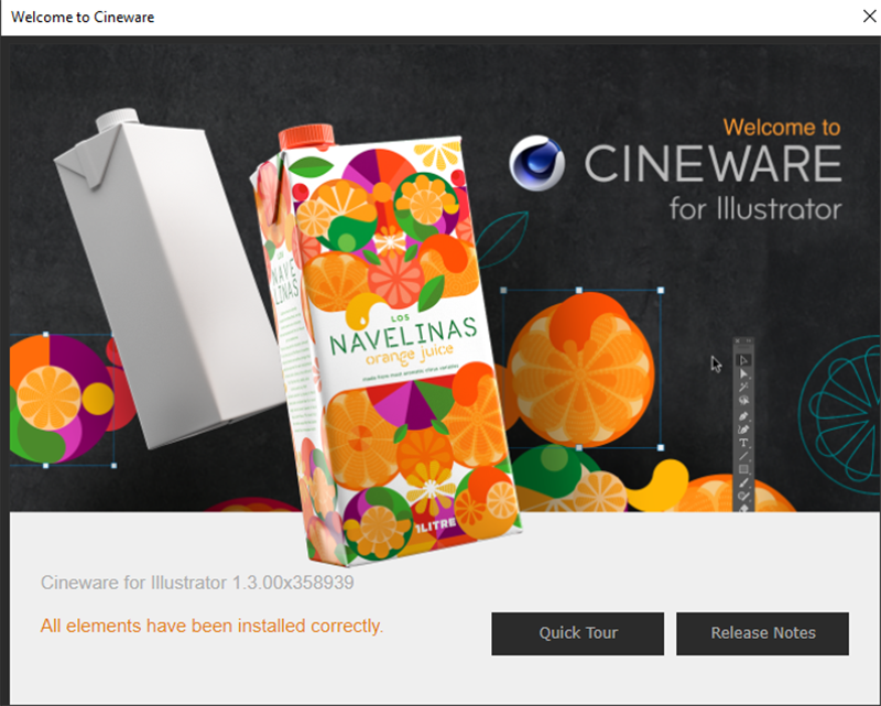
 A Cineware welcome window in Adobe Illustrator after successful installation of the plug-in.
Overview
The first time Adobe Illustrator is started after Cineware has been installed, an info window appears that provides information about the plug-in and a brief introduction.
 A Cineware welcome window in Adobe Illustrator after successful installation of the plug-in.
The welcome window provides access to different information via two buttons.
Clicking the Release Notes button displays information about the installed plug-in and its previous versions. Here you can, for example, check if the installed Cineware version is compatible with the Adobe Illustrator version that is installed.
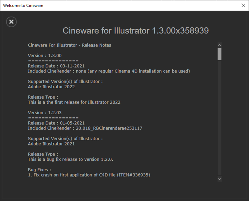 Release Notes for Cineware.
Clicking on the Quick Tour button brings up various info panels that first familiarize you with typical Cineware controls and then point you to complementary products and sources for 3D elements.
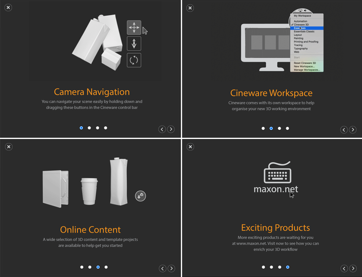 Quick Cineware tour
In this context, some products can later be downloaded directly from the Cineware interface as free 3D objects, which are offered in cooperation with Turbosquid. Many of these objects are already prepared in such a manner that colors or textures can be assigned directly in Adobe Illustrator.
 Some of the free objects that can be loaded directly.
To open our Cinema 4D project to Adobe Illustrator, two options are available:
In both cases, the size and position of the 3D view can still be adjusted afterwards by dragging the border points of the placement frame. As usual, the aspect ratio of the display can be adjusted proportionally to the original size by pressing Alt + Shift .
If no pictorial representation of the 3D elements is visible, the connection to the installed Cinema 4D version might be faulty, because Adobe Illustrator must be able to communicate with Cinema 4D for the representation of the 3D elements.
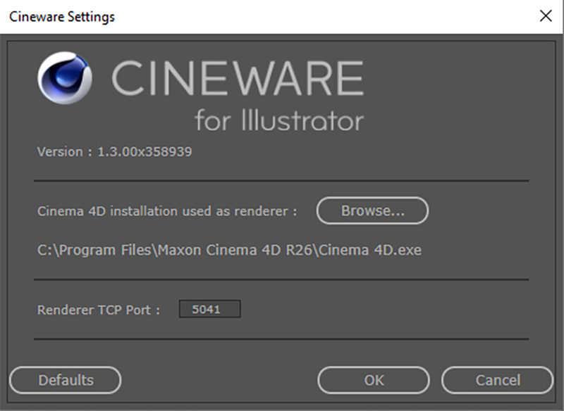 The Cineware settings
In such a case, open the Cineware preferences via Window>Cineware>Preferences... and check there whether the path to your Cinema 4D installation is up-to-date. Otherwise the program path can be updated via the Browse ... button. The selected Cinema 4D version must also have an active license.
In most cases you won't have to make any changes to the settings on the Port number displayed. If you encounter problems you should make sure that this port is not blocked by your firewall to ensure unencumbered communication between Adobe Illustrator and Cinema 4D.
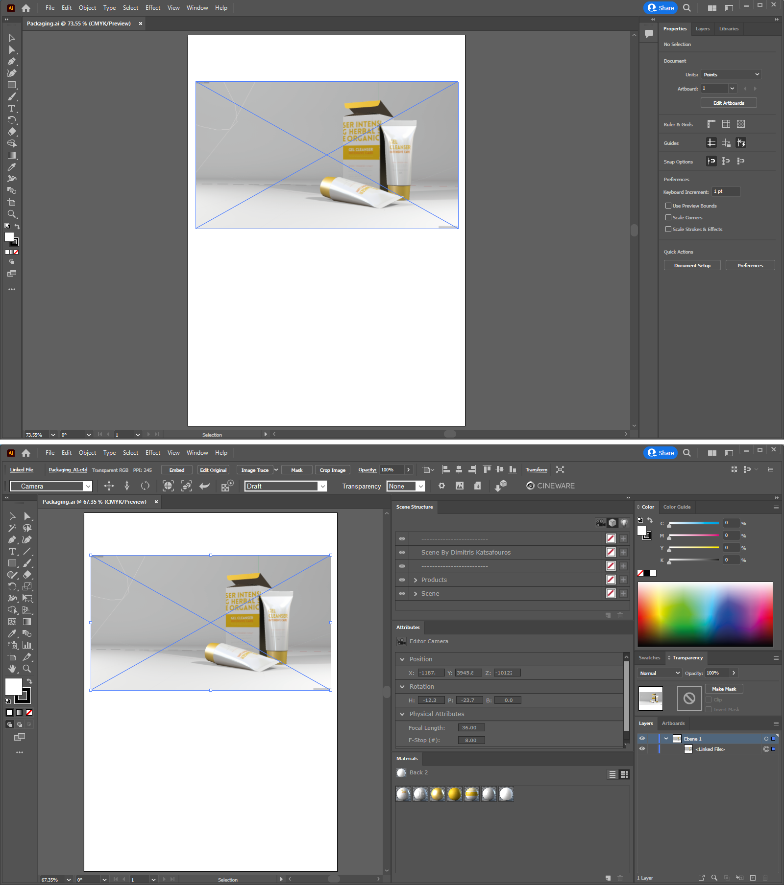 In the upper half, you can see a placed 3D view with the default Adobe Illustrator layout. Below this the same document but with a special Cineware layout.
If the connection to Cinema 4D works, you should be able to see a representation of the 3D elements inside the transformation frame, as in the top half of the figure above.
To control the quality of the display, access the navigation elements and to manipulate 3D objects, lights, cameras and materials you should switch to the special Cineware layout.
This can be achieved by selecting Window>Work Area>Cineware 3D or by switching to Cineware 3D in the Change Work Area drop-down menu. The result can be seen in the bottom half of the image above.
The displayed Cineware Managers and functions can also be configured individually via Window>Cineware. We'll take a closer look at these functions below.
This is the bar that runs horizontally across the document and is mainly used to control the display quality and the perspective used.
|
|
Each Cinema 4D scene contains at least the Editor Camera through which we can view objects in any direction. Within Cinema 4D you can also create any number of additional Camera objects through which objects can be viewed from different angles The camera's focal length can be adjusted to distort the view of the objects. This drop-down menu shows the available cameras in the loaded scene and makes it possible to select the desired camera. The position and angle of view of the selected camera can be adjusted directly in Adobe Illustrator using the following icons. |
|
|
Icons to move, zoom in or zoom out the camera and to rotate the viewing direction. Simply click and move the mouse on the respective icon. The first icon with the four arrows can also be operated by right-clicking on it and can also increase or decrease the camera's distance to the target element. |
|
|
Clicking on the first icon zooms in on the selected objects and displays them centered. The second function automatically centers all objects in the view and adjusts the camera's distance from the elements accordingly so all elements are visible. |
|
|
This function sets the selected camera to its original position saved in the Cinema 4D scene, undoing any changes made to the viewer position and perspective. |
|
|
Turning this feature off limits the updating of the rendered image. Only modifications to the perspective, Render Settings objects or materials will result in a recalculation. |
|
|
The display quality can be regulated in different levels. The Draft mode reflects the simplest display type that can be quickly updated. This is particularly helpful during changes to camera position and when adjusting the angle of view or focal length. In this mode, however, additional lines are visible, as are created by light sources or cameras. The following modesLow Quality and High Quality are fixed quality levels for the Cineware connection that must be rendered and thus contain all effects and properties of the Cinema 4D scene. The calculation times of these quality levels depends on the rendering's image resolution and the active effects (e.g., Ambient Occlusion or Global Illumination) that were defined in Cinema 4D. The Render Settings defined in the Cinema 4D scene are only applied in Custom mode. |
|
|
The Cinema 4D scene can contain various masks that can, for example, be used to separate individual objects. These can be added via Multi-Pass effects or Compositing tags This menu contains available masks from which you can choose. Note that the masks cannot be calculated in Draft mode. Also the names of the available masks are only visible for other display types that are used to render. The alpha mask is always available and covers the areas of the display in which no objects can be seen. |
|
|
The cogwheel opens the Render Settings of the loaded scene in a reduced form. Here, only the render resolution and the image to be displayed can be selected. This can be helpful for an animated scene if a specific movement phase, e.g., for a particle stream, should be displayed. The second icon calculates the image of the 3D view in full resolution as defined in the Render Settings and saves it to a location defined by you. This also works, for example, in Draft mode. The third icon saves the current state of the 3D scene as a new Cinema 4D file. This will then also contain camera angles, light settings and material assignments made in Adobe Illustrator. |
|
|
This can be used to open a window from which additional 3D models can be loaded, which have been made available free of charge by the provider Turbosquid, among others. |
|
|
This button opens a special Cineware for Adobe Illustrator web page, where you can also find numerous short videos describing tips and typical workflows. |
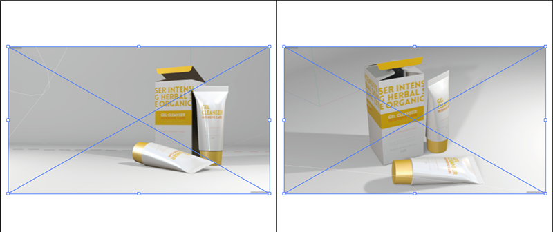 Change the perspective using the Move and Rotate icons in the Control Bar. The original perspective can be seen on the left, on the right is the modified angle of view from Cineware.
Using the navigation icons from the Cineware Control Bar allows you to adjust the perspective afterwards. The big advantage of three-dimensional objects is that these can be viewed from all sides. Note that in many projects the lighting was optimized for a specific angle of view. The back side of a given object can therefore not be illuminated sufficiently. Also, a surface's highlighting can be negatively affected if the angle of view on that object is changed. In such cases, the position and direction of the light source(s) must also be adjusted, which can only be done in Cinema 4D
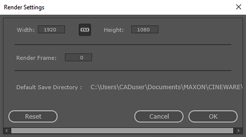 The Render Settings allow you to adjust the render resolution and select the animation image to render directly in Adobe Illustrator.
The Render Settings provide you with an overview of the image resolution actually used, as created via the render presets in the Cinema 4D scene. The resolution can be adjusted here as well if the display should, for example, be much smaller or larger. Disabling the chain symbols can also change the display's aspect ratio if, for example, the landscape format should be made to portrait.
For Render Frame you can enter the frame number of the animation image to be displayed. This only plays a role if objects or properties were animated in the Cinema 4D scene. It is, for example, possible to calculate the intensity of lights, the camera or object positions or the deformations in an animation. In such cases you can navigate via Render Frame to the exact location of the animation phase that you want to display as an image. At the bottom of the dialog window a file path is also shown where the linked Cinema 4D file is located.
To the right of the document view, you will find various Managers in the Cineware layout that allow you to make changes to the objects and materials, for example. The top-most Manager is the Scene Manager and lists, among other things, the components of the loaded 3D scene.
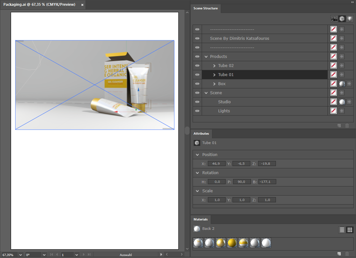 The Scene Structure Manager lists the components of the loaded scene and is located at the top right of the document view.
At the top right of this Manager you will see three icons that allow you to filter the type of elements you want to see in the Scene Structure:
The elements of a 3D scene can be grouped hierarchically. Objects can be made Child objects. Such hierarchies can be quite complex. It can therefore happen that an object you're looking for can only be found if the hierarchy is opened in the Manager. You can recognize hierarchies by the arrow icon on the right next to the name of the entry. Clicking on this arrow will display the subordinated entries for that element. The arrow will point downward. This can be seen in the image above, e.g., on the Products group under the two Tube objects and the Box object. These elements also in turn contain other objects, as you can see based on their closed arrow icons. It can therefore be the case that you must open multiple arrows in order to locate deeper-lying objects as is the case with the cap models for both tubes.
Generally, it is helpful if all objects have already been named appropriately directly in Cinema 4D, but this cannot always be assumed, especially if scenes have not been created by yourself. You will therefore also be given a square outline of the currently selected object in Draft view mode as well as a display of the axis system, as shown in the image above for the standing tube, which is listed in the Scene Structure Manager as Tube 01.
To the right of the object names, you can also see other icons.
The first icon with the red line on a white square will remove all existing materials from that object when clicked upon. Subordinate objects will not be affected. This function also works for individual objects.
The Plus icon lets you select an existing material with which that object should be textured or colored.
If a material was already assigned to the object, this can be seen by the spherical icons next to the object in the Scene Structure Manager. Such icons can be clicked on and selected in order to edit the respective material or projection settings in the Attribute Manager. This will be discussed in a subsequent section.
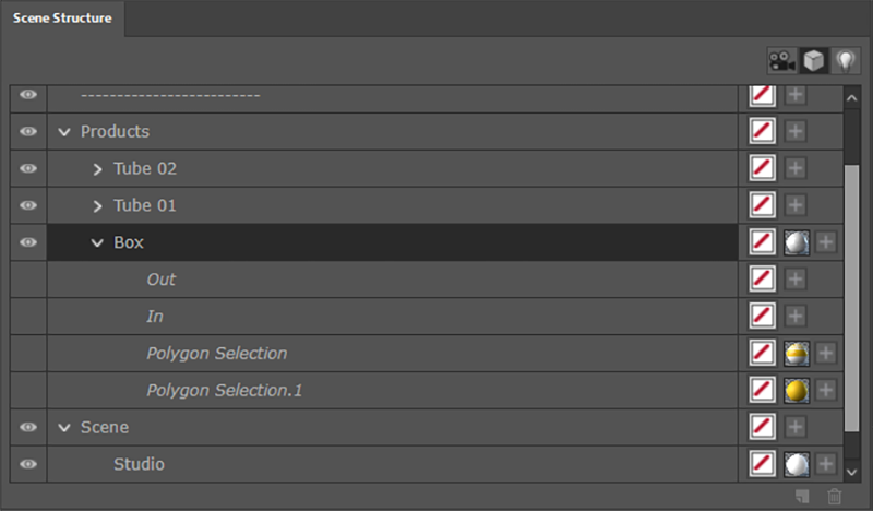 Material assignment to a polygon selection is also supported.
The use of saved surface selections is also supported, provided they have already been created in Cinema 4D and saved as a Polygon Selection tag. In such cases, you will find italicized entries below the objects, as can be seen in the above image with the Box element. Here you can also use the Plus icon to place materials only on these selections. In the case of the folding box, for example, the lid was given a different texture than the vertical surface. In addition, materials can also be layered, as you can also see on the Box element in the image above.
A gray paper material lies on the Box and covers the entire surface. The subordinate selections automatically lie above in the hierarchy.. Materials assigned here automatically cover the basic paper material on the Box at the locations saved in the selections.
You can also assign multiple materials to the same object entry. The material farther to the right next to the entry automatically covers the materials to the left. This principle reflects the evaluation of the Material tag in the Cinema 4D Object Manager.
This can be helpful, for example, if a material contains masked out regions. In these transparent regions you can see a material on the left.
Finally, on the left, in front of each object entry, you will find the typical eye symbol, with which you can hide elements. This way you can, for example, also turn light sources on or off.
In this Manager you will find settings for the selected element. Here are the values for the position and orientation of objects in space. As well as object-specific settings such as focal length for cameras or the intensity and color of light sources.
Camera attributes
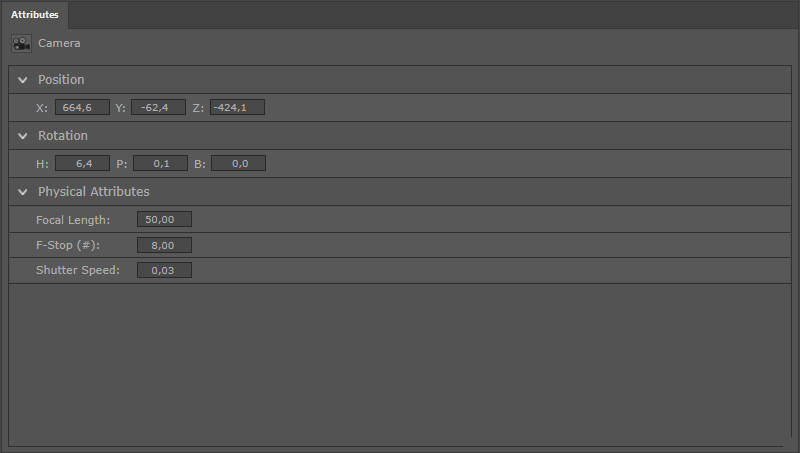 Attributes for a selected camera
If a camera is selected in the Scene Structure Manager its position and rotation coordinates will be displayed in the Attributeswhere they can also be modified. As shown at the bottom part of the image above, the camera settings for Focal Length), F-Stop (#) and Shutter Speed are displayed. These settings are explained in detail in the Physical Camera section.
Light attributes
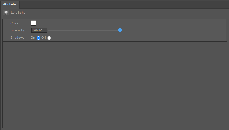 Attributes for a selected light source
For a selected light source, the color of the emitted light, as well as its intensity, are offered as parameters. As shown in the image above, the calculation of shadows by a light source can be enabled or disabled.
Object attributes
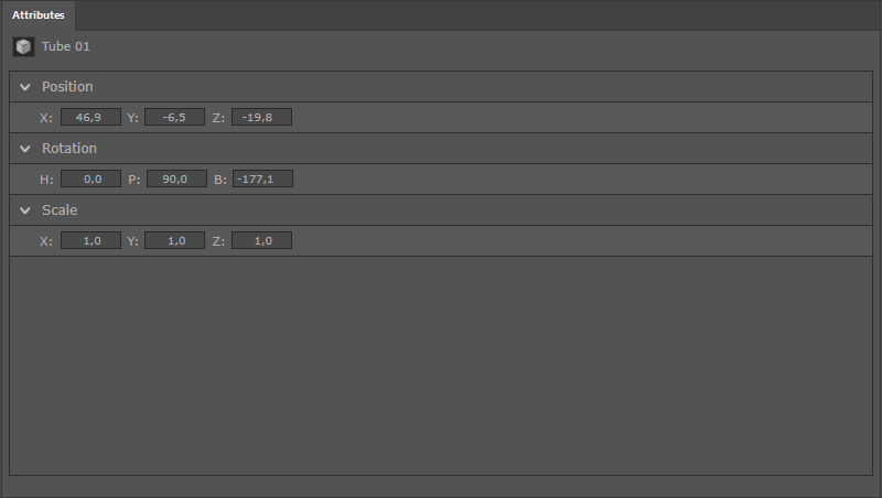 Attributes for a selected object
The figure above shows the attributes of a selected object, with the settings for Position, Rotation and Scale. The Scale setting defines the length of the three object axes that measure one unit by default. By modifying these values, an object can be scaled individually or its shape can be distorted. The default values of 1, 1, 1 will return an object to its original size.
Material attributes
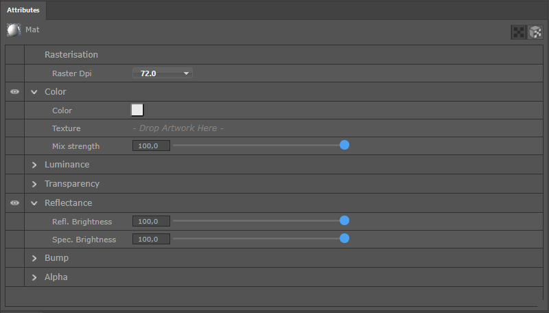 Material parameters
When clicking on an assigned material, two different panels are offered in the Attribute Manager, which can be switched via icons in the upper right corner. The image above shows the settings for the first parameter page on which you will find the materials channels and their settings as well as the selection menu for DPI for material display. These settings are described in detail in the Standard Material System section.
In order that the properties of a material channel can also act on the material, the preceding eye symbol in the left column must be activated. This can be seen in the image above, e.g., in the channels for Color and the Reflectance properties.
Some channels also offer the use of textures. In the Color list above you will also see a Texture entry. By dragging a bitmap onto the Drop Artwork Here field, a texture can be exchanged within a material or reassigned within Adobe Illustrator. Adjusting materials and texture projections on an object's surface is then defined on the second settings page of the Attribute Manager.
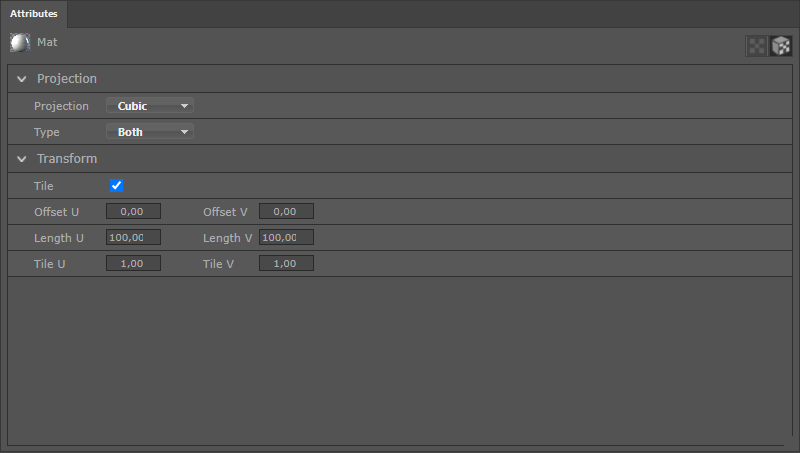 Projection parameters
As can be seen in the figure above, the type of projection can be switched here, as well as the scaling and the repeat behavior can be influenced. This kind of data structure is already well known from the Material Tag within Cinema 4D.
In this section you will find the materials available in the scene. Additional materials can also be created here via copying. The Material Manager offers two different display modes for materials that are shown in the image below. These modes can be switched using the icons at the top right of the Manager.
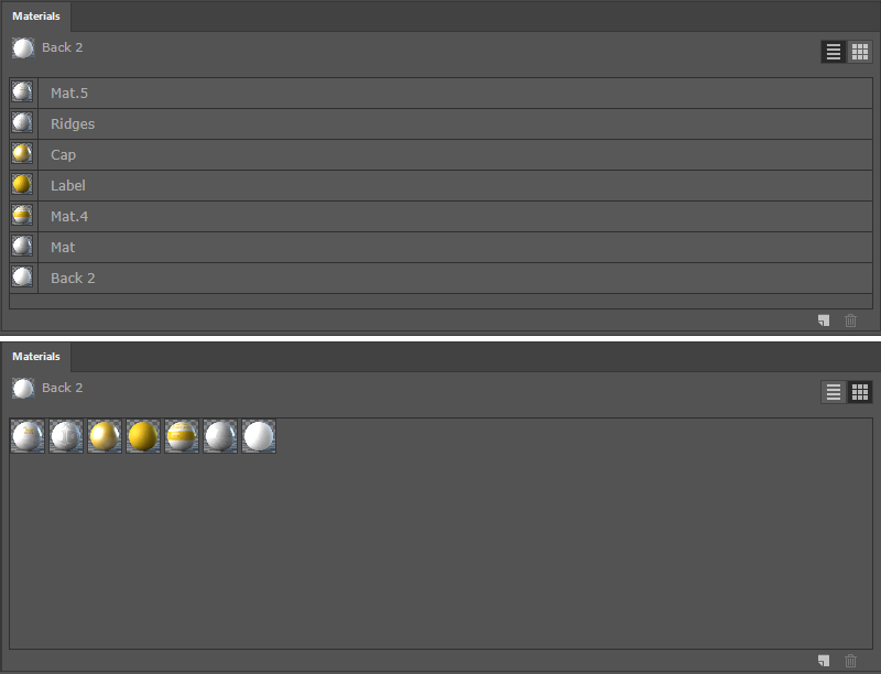 Different display modes of the Material Manager
In List mode, small thumbnails of the materials appear in the left column, followed by their material names in the right column. In this mode, the focus lies on the good readability also of the longer material names, which can be helpful if the material thumbnails look very similar.
When switching to Tile mode, the material name will no longer be displayed. In turn, the preview areas of the materials appear somewhat larger. In any case, materials can be selected by clicking on them in this Manager, which displays their settings in the Attribute Managerwhere they can also be modified.
In the lower right corner of the Material Manager you will also find two more icons. Clicking on the trash can symbol will delete the selected material(s). Clicking on the document symbol next to it will duplicate the selected material(s). A dialog window will open, which is shown below.
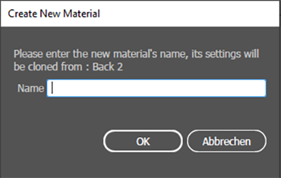 Dialog when creating a material copy
As shown in the figure above, this dialog allows you to assign a new name to the copied material. Otherwise, the properties of the copied material will first be assumed and can then be adjusted individually in the Attribute Manager.. This new material can then be reassigned via the plus symbol in the Scene Structure Manager.
Masks can be used for even more flexibility when incorporating and combining the 3D elements with other graphic elements. Ideally, planning a scene in Cinema 4D scene includes the placement of alpha masks. This was already discussed in the section about preparing a scene for Cineware export. These masks can be called up directly in the Transparency in the Cineware Control Bar. In order for the effect of these masks to actually be calculated, the Draft mode must be disabled.
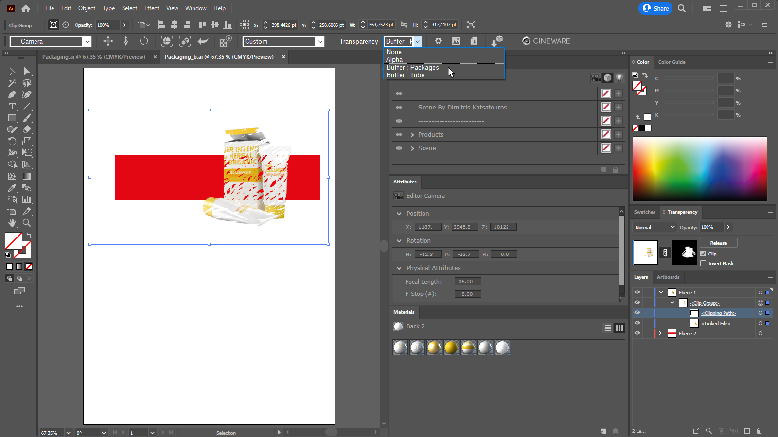 The use of masks and transparencies in our example scene.
Blanked 3D elements can be placed on alternative backgrounds or arranged on top of each other via Cut and Paste Before or Paste Behind. Furthermore, the opacity of the 3D elements can be controlled directly in Adobe Illustrator via the transparency masks, as is shown in the image above.