Tag Properties
You can drag and drop materials from the Material Manager into this field. If you have selected several Material Tags, you can assign a new material to all of them together.
When using classic Cinema 4D materials, you can also carry out "material morphing" via the animation of this field, i.e. fade continuously between two materials. With Redshift materials, comparable effects can be realized directly in the Node Editor via corresponding nodes.
If you click on the small arrow to the right of the field, a menu with the following entries will open:
Delete
Deletes the current material from the Material tag.
Show in manager
Displays the associated material in the Material Manager.
Select element
Selects the corresponding material in the Material Manager.
The Selection field gives you the option of texturing the object with different materials at certain points only, without having to separate the corresponding areas into separate objects beforehand. This makes it easy to add labels or similar to objects. To use this function, you need a Polygon Selection Tag (e.g. .). This contains either a manually created selection or one created by a field.
Otherwise, you can enter selection names (tab based on the Selection Tag) here by simply dragging and dropping the tag into this field.
The functionality works hierarchically, i.e., a Material Tag with a defined selection field projects the material onto all sub-objects with a corresponding Selection Tag.
You can read more about handling selections under Select menu.
 An object with different textures
Please also note the invisible selections of certain generators (e.g., Extrude object, Text object etc.) as described here, for example.
Projection is the way in which a texture image is projected onto a surface. This surface has nothing to do with the actual surface of the object, but may happen to have the same shape (Spherical, Cubic, Flat, etc.).
With UVW mapping (see later), the projection is linked to the surface points of an object. Here, the projection itself is distorted according to the changes on the object surface.
Not every projection type is equally suitable for every object geometry. We will show you this using the first three mapping methods (Flat, Spherical and Cylindrical) as examples.
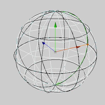
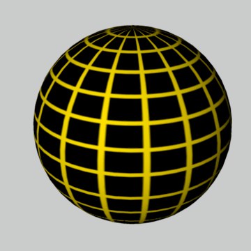
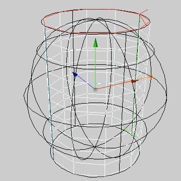
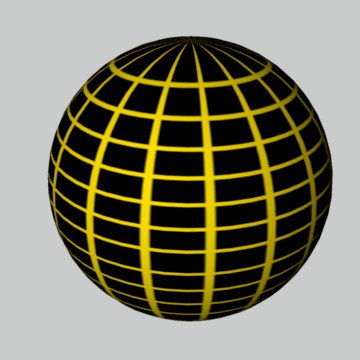
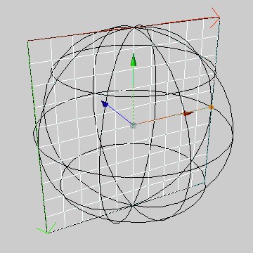
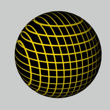
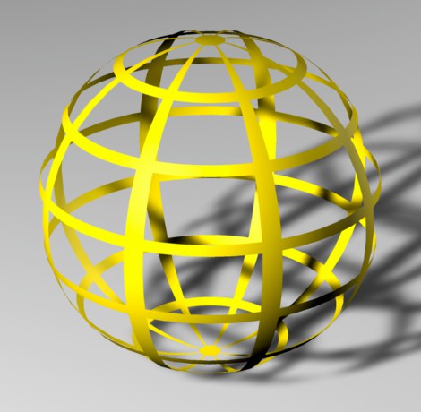
If you set this projection type, the texture is projected radially (spherically) onto the object.
|
|
|
|
|
|
Spherical projection is almost never suitable for flat objects, as distortions also occur on the top surfaces of cylindrical objects.
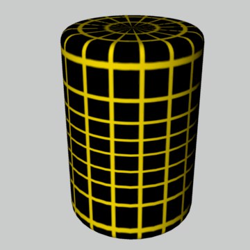
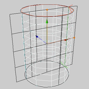
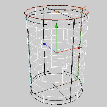
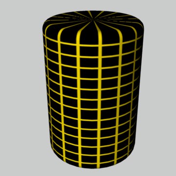
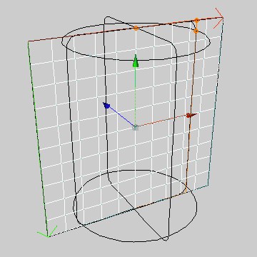
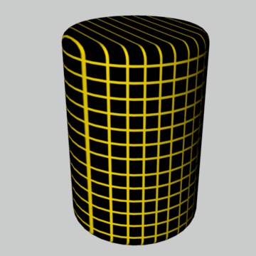
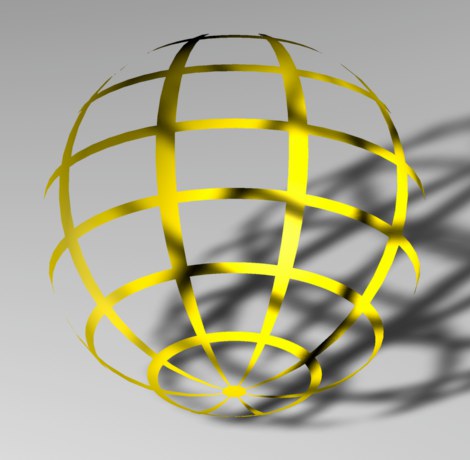
If you set this projection type, the texture is projected onto the object in a cylindrical shape.
|
|
|
|
|
|
The Cylindrical Projection is almost never suitable for flat objects. Distortions also occur on spherical objects. Note that the uppermost (and lowermost) pixels of the texture image on the top surfaces of the cylinder are drawn radially inwards. Use separate textures for these separate objects.
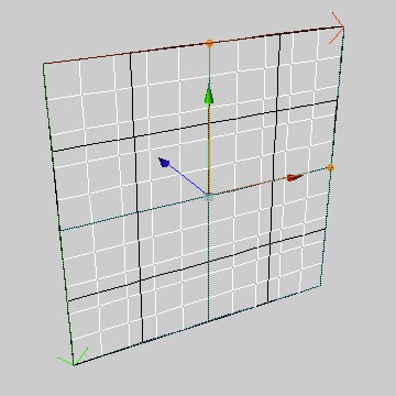
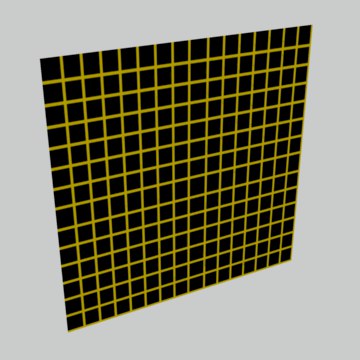
If you set this projection type, the texture is projected flat onto the object.
|
|
|
|
|
|
As you can easily see, the surface projection is in most cases only suitable for flat surfaces. On round objects, distortions quickly occur, as you can see from the cylinder and the sphere.
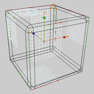
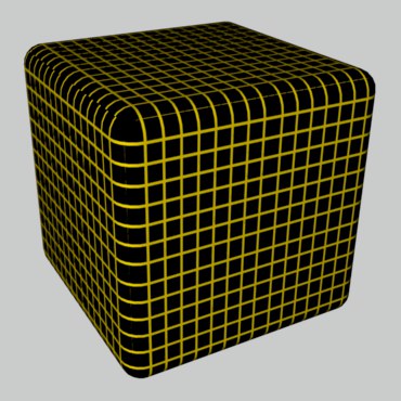
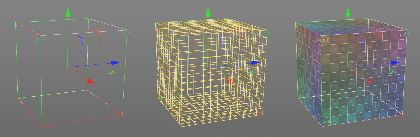
If you set this projection type, the texture is placed on all six sides of a texture cube. The surface normals of an object are used to determine which of the polygon sides (depending on whether the normals point inwards or outwards) is used for the projection.
|
|
To give you a better idea of where the texture is applied to the cube, we have halved the size of the texture in the illustration on the left. In the illustration on the right, the lengths are set to 100% again.
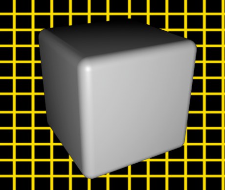
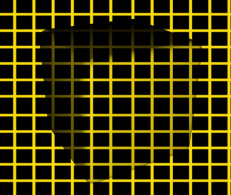
If you set this Projection type, the texture is always projected onto the object from the camera's point of view, whereby the texture (with the same offset and length values) matches the foreground/background image exactly.
|
|
This mapping method can be used to achieve spectacular effects, making it ideal for video compositing.
The image on the right shows very nicely how the cube appears to disappear when Frontal mapping is used - only its shadows remain. Instead of the shadows, it could have been highlights or similar. Leave out the background image and move the cube instead (position animation).
Camera Mapping is the process of mapping textures onto an object from the camera's perspective.
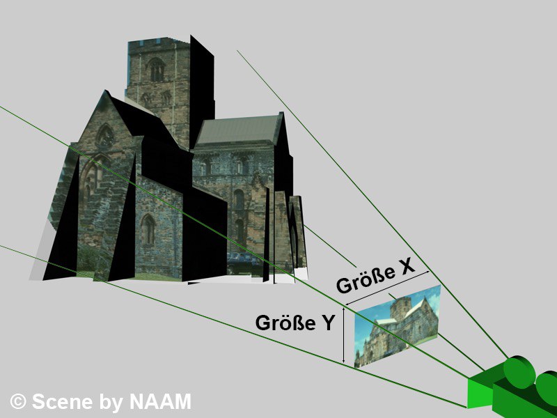
Imagine you want to animate something in a real image. That wouldn't be a problem if the camera didn't have to move a little to the left or the animated object didn't have to disappear behind the depicted building. You can now fall back on Camera Mapping.
First, you need the image that is to be placed on the object. Create a new material and load the corresponding image on the Color page. Project the new material onto the object using Camera Mapping. To do this, you need a camera from whose view the material is to be projected. You should also assign the camera to an editor view (Editor: Cameras / Use Camera / Camera XXX).
Now either simply recreate the scene in which you want to move the camera, for example, or just the area behind which you want your animated object to disappear. Combine all the individual objects into a single object and use Camera Mapping to give the new object the same texture as the previous background object.
To be able to move around the scene later, it is now important to fix the textures to the corresponding objects. To do this, select the corresponding Material Tag in the Object Manager by single-clicking on it. The symbol will be framed. In the Object Manager menu Tags, call up the entry Create UVW Tag. The texture has now been fixed to the object geometry and you can now move the camera around the scene.
Settings
Drag in the camera from whose viewing direction the texture is to be mapped.
Enter the width to height ratio of the projected texture here. This is entered automatically when you use the Projection Man or click on the Calculate button. You have a list of common film formats in the selection menu.
If the texture deviates from a normal pixel ratio of 1:1, enter a different Pixel Aspect here. By the way, clicking on Calculate always outputs 1:1, as this information is not contained in a bitmap. You have specified a list of common pixel formats in the selection menu.
When you click on this button, the corresponding properties of the texture to be mapped are entered for Film Aspect and Pixel Aspect (here always 1:1). This allows you to enter the same resolution in the Render Settings. The scene is then rendered in the same size as the texture.
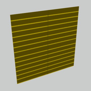
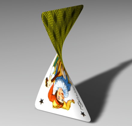
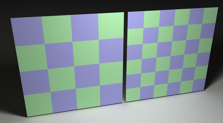
This type of mapping is very similar to Flat Projection, but now the image is not simply projected straight to the rear, but at an angle (to the left and upwards for frontal views).
|
|
In the image on the left, the stripes are clearly visible when the Flat Projection is used. In the image on the right, we switched to Spatial Projection. Although you cannot see the course of the Spatial, it is important to note that the stripes on the sides of the object have disappeared.
Spatial mapping is less suitable for image motifs (or, as here, the grid texture), as it causes distortions, and should therefore be used for structural textures (e.g., plaster, marble, ...).
If an object has UVW coordinates, these can be used for texture projection, whereby the texture geometry is fixed to the surface of the object and from then on follows all movements and distortions.
The essence of UV projection is also explained here.
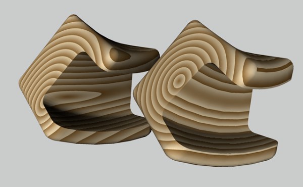
For example, if you want to design the image of a book page that is turned, the texture follows the curvature of the object.
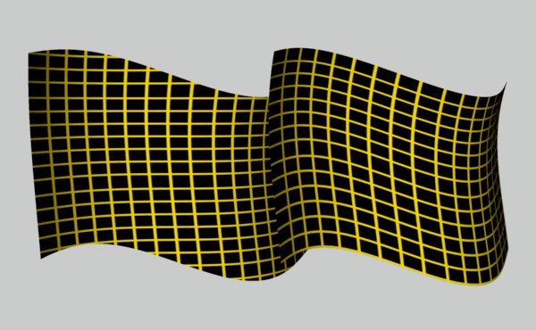
Conventional Flat Projection was used on the left in the illustration, while UVW mapping was used on the object on the right. You can clearly see how the texture follows all the bends of the object.
All basic objects and generators in CINEMA 4D are equipped with UVW coordinates by default. If you assign a new texture to these objects, the UVW mapping is automatically set in the texture geometry.
The UVW coordinates are displayed with a corresponding symbol for polygon objects.
The basic objects and generators have internal UVW coordinates that are not displayed with a symbol. You can still apply the UVW mapping to these objects. If you convert one of the basic objects into a polygon object, the set parameters are applied.
You have probably already wondered what the third coordinate, the W coordinate, is good for. You will now find out!
Why also a W coordinate?
Every texture you use has two coordinates: the horizontal position U and the vertical position V. UV coordinates would therefore appear to be sufficient if it were not for the 3D shaders. These are three-dimensional textures (see Cinema 4D shaders), which must also be fixed in three dimensions if you want the texture to deform with the object. The W coordinate is required for this. It also fixes the shader in the depth W.
To activate the W coordinate for the 3D shaders, assign the Material Tag from the Object Manager in the Tags / Material Tags menu to the corresponding texture geometry. The 3D shader can now also be deformed on the object.
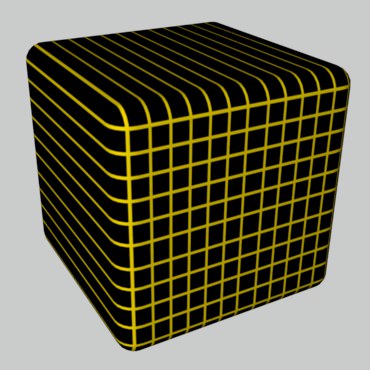
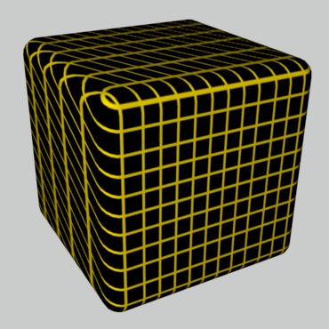
 Left without, right with fixed W-coordinate
Multiple UVW coordinates
When texturing your objects, you also have the option of using more than one UVW texture geometry. To do this, assign a new texture geometry to the object, set a corresponding projection, e.g. the Flat mapping to apply a label, and create a new UVW tag for the active texture with Generate UVW Coordinates. The active texture geometry has now been switched to UVW mapping and adapts to the surface of the object when it is deformed. The worst "enemies" of a mapping (morphing, magnet...) can now no longer harm the object.
Each time you call up Generate UVW Coordinates, a new one is added to the existing UVW tags. A Material Tag (with UVW Mapping activated) will always use the UVW Tag directly to the right of it in the Object Manager. If no such tag is available, the first UVW Tag available will be used. In this way, different UVW Tags can be assigned to different Material Tags.
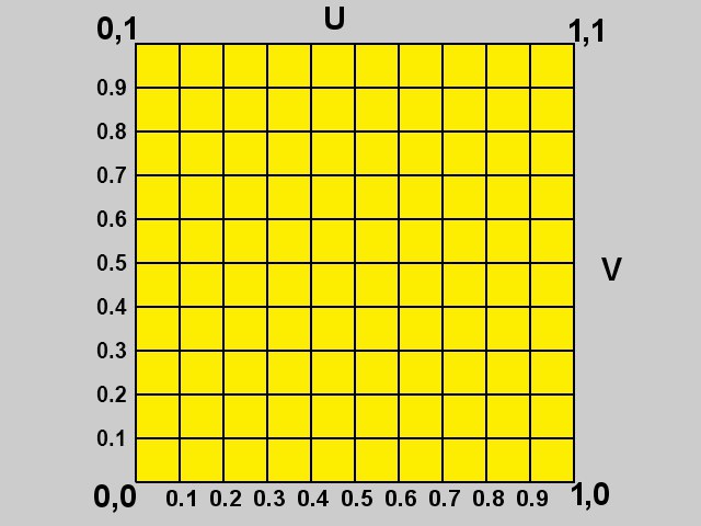
The UVW coordinate system
How are the UVW coordinates structured? Imagine a grid that is divided into U and V directions.
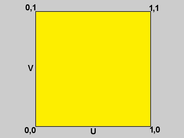
The UV value range starts at the coordinate 0.0 and goes up to 1.1. In the case of an upright polygon, 0.0 now describes the lower left, 0.1 the upper left, 1.0 the lower right and 1.1 the upper right support point. A texture is now "spanned" between these four coordinates. If you have, for example, a subdivided plane instead of a single polygon, the UV range is split between them from 0.0 to 1.1.
But where is the W coordinate in this system? Since normal image textures only have two dimensions, the W coordinate is only generated when required, as described above. Once generated, the W coordinate behaves in the same way as the UV coordinates and has the same structure.
Selective UVW mapping
There are two ways to assign polygon selections to texture projections in Cinema 4D. The second option, the Selection function, is described above.
With selective UVW mapping, you have the option of texturing several areas of an object with different projection types using one texture geometry.
How to proceed
- Create a sphere and convert it into a polygon object using the Make Editable function.
- Create a new material with a texture, e.g., the check shader, and assign it to the sphere.
- Change the projection type from UVW Mapping to e.g., Flat Mapping.
- Activate the Polygon tool and select some polygons.
- Call up the Assign UVW coordinates function in the Tag Object Manager menu.
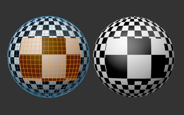
You can already see that the selected area has been provided with the Flat Projection and the deselected area with the normal UVW mapping. If you now deform the object, the texture remains fixed in the selected area.
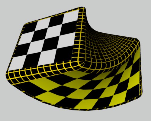
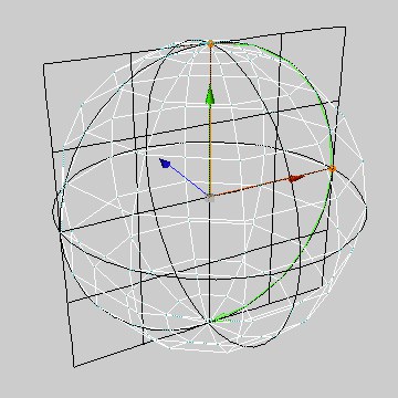
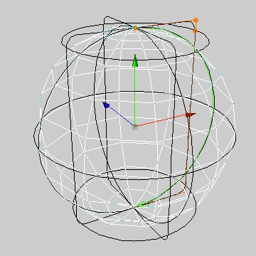
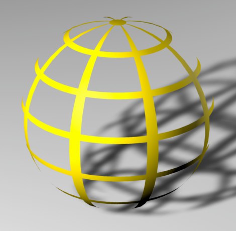
With this type of texture projection, the center of a texture is pinned to the top of a sphere (north pole) and the rest is placed over the sphere. The advantage of this type of mapping is that the texture only collides at the south pole - in other words, unlike the Spherical Projection, no longitudinal seam is visible with non-tileable textures.
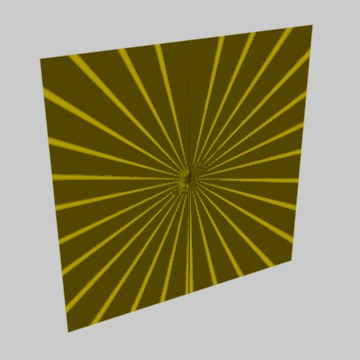
Due to this projection method, only a circular section of the texture image itself is used (with the center of the image as the center of the circle); the rest of the image is omitted.
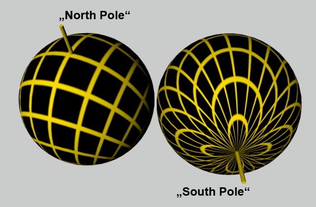
You can clearly see how the texture image converges at the south pole (left).
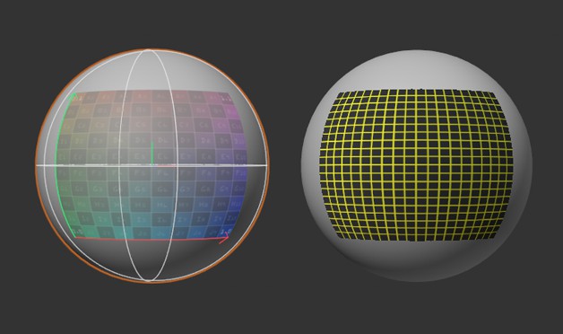
Define here how the auxiliary projection view to be adjusted interactively in the view should be displayed in the view:
- Simple: only the projection shape is displayed.
- Grid: a yellow grid is displayed.
- Full: the texture shown in the illustration on the right is displayed, making it easier to assess the alignment.
A grid is always displayed in the Frontal Mapping Projection.
 Projection display Simple, Grid and ull.
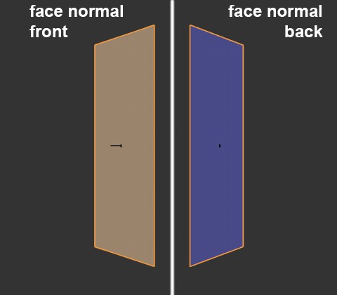
Imagine you place an image on a rectangle using Flat Projection. If you now look at the rectangle from behind with the camera, you will still see the image, but this time inverted. To avoid this, there is the Side option. This option allows you to project textures onto only one Side of a polygon.
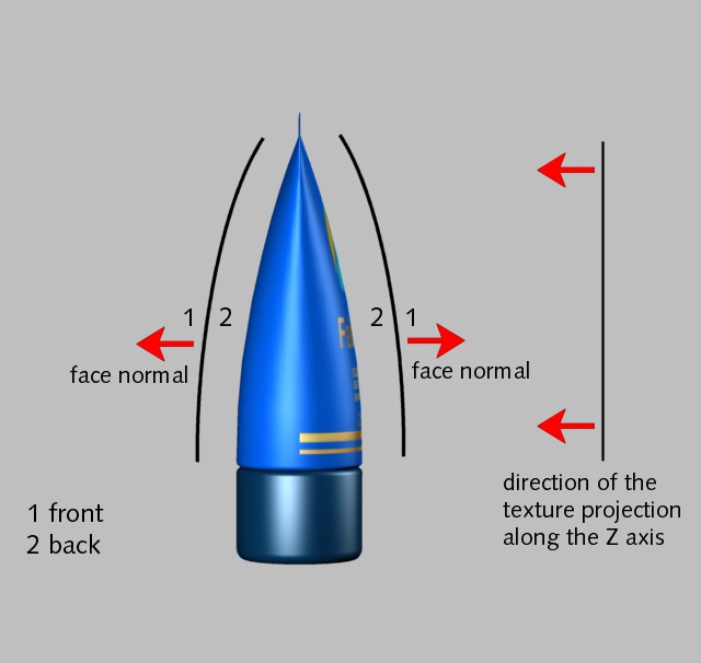
It is very important to know how Side Mapping works. The surface normal (can be visualized here: Polygon Normals) helps to decide which side a texture is applied to. Front is always in the direction of the surface normal and Back means against the surface normal.
Example:
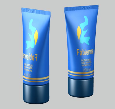
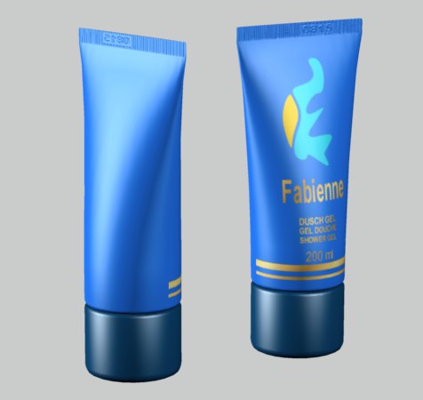
You want to apply a label to a tube of cream. This should be quite easy with the Flat Projection. Have your tube renderd. But what is this? The texture is mirror-inverted on the back of the tube.
|
|
What has happened here? With the Flat Projection, a texture is projected through an object from Front to Back. This means that the texture is also visible where it is not desired. This is where the Side Mapping comes in. In the texture geometry, change the setting from Both to Front. Now rerender the tube. The label is now only visible on the front.
The explanation for this is quite simple. If the visual ray and the surface normal form an angle of less than 90° (i.e. towards each other), the texture is on the Front, otherwise it is on the Back. The only exception is Flat or Spatial mapping. Here, the Z axis of the texture projection is also relevant for the Front criterion. So if the Z axis of the texture projection points against the surface normal, the texture is visible at the Front. If the Z axis of the texture projection points in the direction of the surface normal, the texture is not visible.
If you select Both, the texture is projected onto the front and back of each polygon, regardless of which mapping type was selected.
 Front & Back
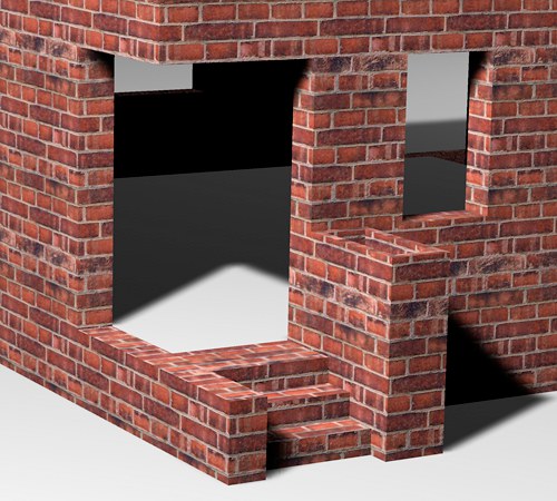
If you have selected Front, you will only see the texture if the surface normal points in the direction of the camera viewpoint. If you have not assigned a second texture, the material will be invisible against the surface normal.
If you only project the texture from Back, you will only see the texture if the surface normal is pointing in the opposite direction to the camera viewpoint. The material is "invisible" in the surface normal direction if you have not assigned a second texture.
 Two different textures projected from the front and rear
In the previous example, a wall material was created with a Color and a Relief channel. When calculating the image, the Relief channel creates the impression that the wall has joints and grooves. Now, however, an additional Relief structure is to be added to the wall, for example, without having to change the texture itself. Impossible you say ... no problem with Cinema 4D we say!
The function is called Add Material and is extremely powerful. It can be used to add new textures to existing ones. As the name suggests, the respective material properties are added.
For example, the sum of the colors 100/0/0 (red) and 0/100/0 (green) is consequently 100/100/0 (yellow). However, if the green only has a brightness of 50%, only 50% of the color is added. The result would then be 100/50/0 (orange).
Of course, some things, such as fog reduction or the refractive index, are not added together (two materials with a refractive index of 1 would otherwise result in a material with a refractive index of 2), but are only transferred from the additive material if transparency/fog is checked there.
- Any number of textures can be mixed together.
- Only the properties Color, Transparency, Reflectivity, Relief, Displacement and Luminosity can be added.
- Only the properties that are checked in the respective materials are evaluated. Even Displacement is additive.
- Alpha punches out the areas where the additive material should not be added.
- The 3D volume shaders fog and landscape cannot be added.
- Materials to be added (option checked) must appear in the Object Manager to the right of the Material tag to which they are to be added.
There are also restrictions on the use of the Tile option on the Material Tag for some pattern generators, such as the Tile or Pavement Node. For these nodes, the number of tiles can be controlled via the Material Tag, but tiling cannot be switched off.
Please also note that you can find your own tiling options and settings on the Texture Node, for example, to influence the size, offset and rotation of the texture projection.
When using Redshift materials, please follow these instructions.
If you activate this option, the texture image is repeated infinitely on the surface and placed next to each other.
This effect becomes visible if you scale the texture smaller (see Texture) or the texture geometry has not yet been adjusted to the dimensions of the object (see Adjust to object). Otherwise, the texture image fills the entire texture geometry exactly once.
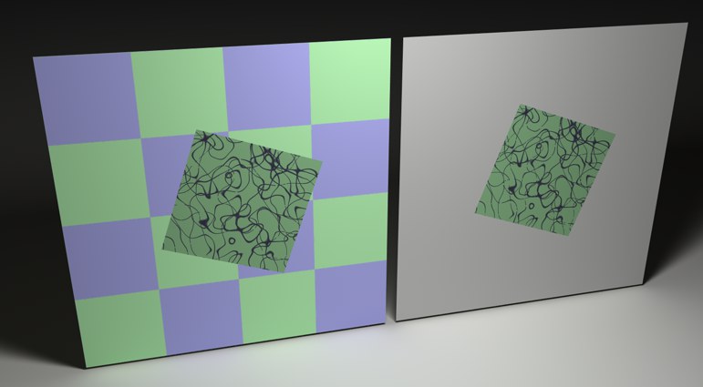 Deactivated tiling with and without second texture
If this option is not activated, you will only see the texture image once on the surface, e.g. a travel sticker on a suitcase. If the object has several textures (see also Texture layering), these may be visible outside the label area. If the object has no other textures, the standard material will appear in these areas.
When using Redshift materials, please follow these instructions.
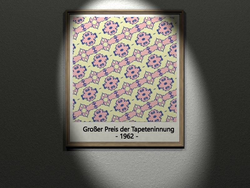
If the Seamless option is activated, tiles are mirrored against each other. This means that you no longer see any seams in non-tileable textures. However, this results in a typical butterfly pattern similar to a Rorschach test or wallpaper of an older vintage.
This option became necessary due to the following situation: The relief was previously always projected with Spherical Mapping despite defined UVW mapping. Since version 8.2, UVW mapping has also been used for this, if defined in the Material Tag. This can lead to problems, as can be seen in the following image:
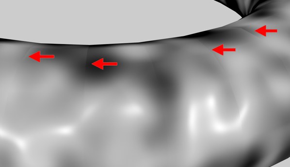 Artifacts with noise shader in the Relief channel with activated option
In the border areas of two adjacent UV polygons (especially when using the Noise shader with a large "Delta"), artifacts occur in certain areas. The reason for this is the discrepancy between the coordinate systems of the object polygon and the mapped UV polygon. This is a general problem and can only be solved by finer resolution of the geometry. Alternatively, the variant used before version 8.2 can also be used, but this leads to artifacts at the pole positions and does not support the realignment of UVWs (e.g.: optimal mapping).
Labels
So, now you know how to apply textures, turn tiling on and off, what you need seamless surfaces for, but no one has taught you how to stick a simple decal on a bottle ... until now!
This is how you proceed:
- Open the Texture Geometry dialog (the properties of active tags can be found in the Attribute Manager).
- Switch off the Tile option, making sure that only one tile is created in both the U and V directions.
However, at the moment the texture still covers the entire object in most cases. The texture must be reduced in size.
The quickest way to do this in the editor is to activate Gouraud or Quick Shading. Switch on the Scale and Texture tools and reduce the size of the texture. Then switch to Move and place the texture in the desired position on the object surface.
In most cases, however, the texture is now distorted in some direction. There is a simple trick to counter this. Open the geometry dialog and enter the extent of your texture in the Length fields. However, as the length must not be greater than 100%, you may have to divide both values.
For example, if your texture is 800 x 600 pixels, you could specify the following lengths:
| U | V | Conversion factor |
|---|---|---|
| 80 | 60 | / 10 |
| 8 | 6 | / 100 |
| 32 | 24 | / 100 x 4 |
etc.
Texture Layering
In CINEMA 4D, you can define any number of materials or texture geometries on an object. Think of it like the travel stickers on a suitcase - you have an object with a base material (the suitcase) and many other materials on top (the stickers).
However, the original case material (e.g. leather, aluminum, etc.) is no longer visible where you attach a sticker. In addition, if there are too many stickers on the case, they will overlap individually; the top ones will then cover the ones underneath. If you still want to see an older sticker, you must either remove a newer one or cut a hole in it.
This analogy can be transferred directly to CINEMA 4D. Your object has a base material. Any number of other materials can be placed on top of it. To ensure that you can still see your base material, the materials above it must be reduced in size. You can do this by reducing the texture geometry and simultaneously switching off the tiling (see Tiling the texture). If two materials on top of each other are covered and you still want to see the lower one, you must cut a hole in the upper one. This is done with the help of Alpha or Clip Mapping(see Alpha page).
The only question now is: what is the base material of the object and what is the topmost sticker?
Very simple: If you assign several materials, they are entered in the Object Manager in the object properties in the order in which they are assigned (see Object Manager). The leftmost material is the lowest and the rightmost material is the highest. You can rearrange this order as required using Drag & Drop.
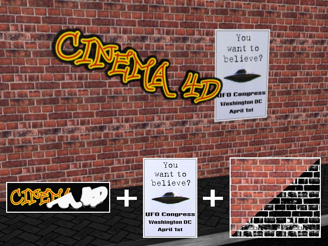
For the above example, a wall material was defined for material T1, a poster material for T2, which was not tiled and reduced in size, and a graffiti font for T3, which was punched out with alpha mapping.
The textures lie on top of each other (in the Object Manager from left to right) in the order T1-T2-T3.
Because T3 (the top texture) has been alpha-mapped, the underlying materials T1 and T2 can be seen, and because the texture geometry of T2 has been scaled down and (important!) the tiling has been switched off (thus not covering the entire object surface), a piece of T1 can still be seen.
Use Offset and Length to define the position and size of the texture image on the texture geometry. When using Redshift materials, please also observe these notes. The settings for scaling and repeating the material should be made directly in the Node Editor, e.g. on the Texture Nodes used.
Otherwise, these are the same values that you can also edit interactively in the editor using the Edit Texture tool (see Texture).
You can use Offset to place the texture on the hull (the texture geometry). Length is used to enlarge or reduce the size of the texture. The U and V specifications for the placement or dimensions of the texture are always given as a percentage, as the actual size is irrelevant. A dimension of 100% for both coordinates means that the texture completely covers the geometry. In the Tiles fields, you make specifications about the tiling of textures.
Tiles
It is often not enough to simply project a texture onto an object. Just think of a brick wall. Do you really want to create a texture for an entire façade, and for all four walls of a house? (There are cases where this may be necessary.) There is an easier way.
All you need is a seamless texture (an image without visible edges) and project it onto the façade, e.g., using cuboid projection and appropriate tiling.
When using Redshift materials, please follow these instructions.
For classic materials, you can use these input fields to specify the number of tiles in the U and V directions, i.e. how often a texture image should be placed next to each other within the texture, i.e. tiled. Cinema 4D calculates the size of a single tile from the current size of the texture. For example, if you have scaled the texture so that it has a size of 25% in the U direction (Length U) and 50% in the V direction (Length V), the texture will fit four times (1.0/0.25) in the U direction and twice (1.0/0.5) in the V direction on the surface.
If you now change Tiles U or Tiles V, the size of the texture changes automatically. If you increase the number of tiles to 3, for example, the texture shrinks from 50% to 33.33%. You can see this immediately in the view.
 On the left, Length U/V was tiled with 50%, on the right with 33%
Repetitions U[0.00..100000.00]
Repetitions V[0.00..100000.00]
When using Redshift materials, please follow these instructions.
If you have defined the tile size with Tiles U/V, you can use these two parameters to set how often tiles should be tiled in each direction.