Tri Planar
Table Of Contents
Introduction
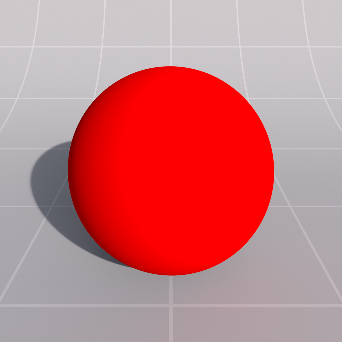
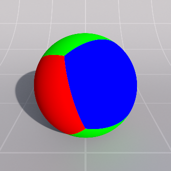
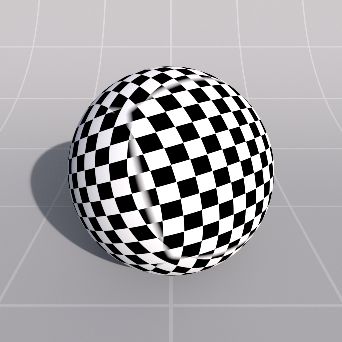
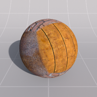
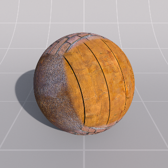
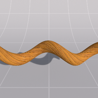
This node allows render-time automatic assignment of UV coordinates, projected on each axis. This technique is useful for surfaces that are difficult to unwrap and bake UV coordinates on and works for color, bump and displacement textures.

|
| Different texture projected onto each axis |
|
Texture
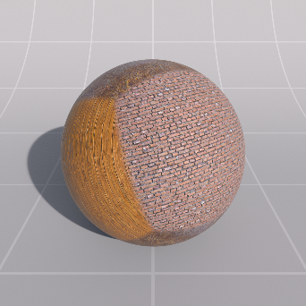
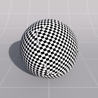
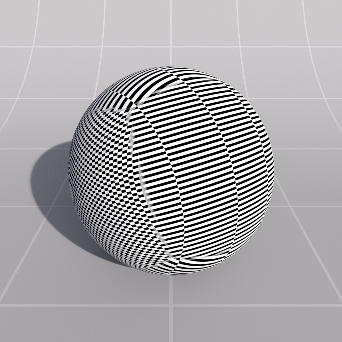
When enabled, this option forces Image X shaders to be executed for all axis projections. When disabled, Image Y and Z shaders will be executed for the Y and Z axis projections respectively.
|
|

|
|
|
Same Image On Each Axis: Enabled RGB |
Disabled RGB |
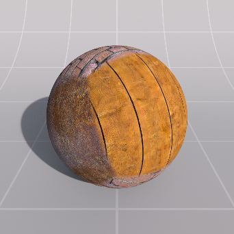
Enabled Textured |
Disabled Textured |
The color for the X/Y/Z axis projections, respectively.
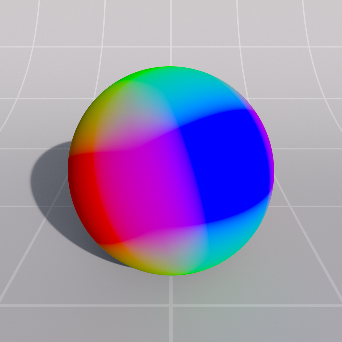
This value dermines how much of the color results for each axis can overlap and be blended together. Having some amount of blending results in a soft transition between axis colors, instead of a hard edge.
|

|

|
| Blend Amount: 0.0 | 0.1 | 1.0 |
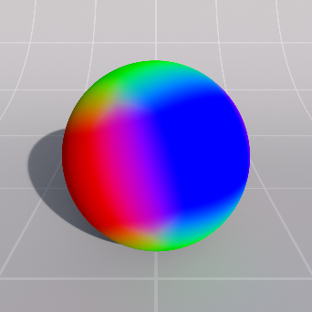
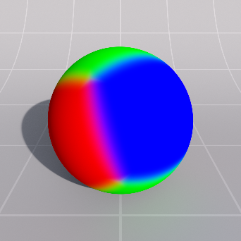
This value determines the power curve of the axis overlap blend and can be used to tighten or slacken the blending effect between axis colors.
|
|
|
|
Blend Curve: 1.0 Blend Amount: 1.0 |
3.0 |
10.0 |
Coordinates
The UV projection for each axis is computed from the coordinates of the object that is being shaded. Because objects can vary in size and location in the world, the options below allow you to tune how the object coordinates are mapped onto uvs.
Controls the number of tiles within a single scene unit. For example, if the World Space Unit is in meters and the scale is set to 2/2/2 then there will be 4 tiles visible within 1 meter squared.
When in World Space mode the unit is controlled by the World Space Unit. When in Object Mode the unit is centimeters.
|
|
|
| Scale X, Y, Z: 1.0, 1.0, 1.0 | 2.0, 2.0, 2.0 | 0.3, 6.0, 4.0 |
These values offset the projected UVs computed for each axis. Combined with the Scale option, the UVs for each axis are modifed like so:
Axis X:
u = (u + Offset.z) * Scale.z
v = (v + Offset.y) * Scale.y
Axis Y:
u = (u + Offset.x) * Scale.x
v = (v + Offset.z) * Scale.z
Axis Z:
u = (u * Offset.x) * Scale.x
v = (v * Offset.y) * Scale.y
|
|
|
| Offset X, Y, Z: 0, 0, 0 | 0.5, 0.5, 0.5 | 2.5, 2.5, 2.5 |
These values, in degrees, rotate each axis UV projection respectively, so the Rotation.X value rotates the X Axis projection etc. This rotation is applied after the above Scale and Offset adjustment.

|
|
| Rotation X, Y, Z: 0, 0, 0 | 45, 60, 90 |
This specifies the projection space type, which determines which object shading coordinates are projected into uv coordinates. The options are as follows:
- World - uses the world-space coordinates that are being shaded. This option will result in texture projection 'swimming' if the object moves or is instanced.
- Object - uses the object-space coordinates that are being shaded. This option undoes the world transform to lock the coordinates to the local object space, resulting in no texture projection swimming when the object moves or is instanced.
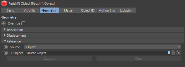
- Reference - uses the object reference pose coordinates, if available. This option results in no texture projection swimming when the object moves, is instanced or is deformed.

|
|
|
| Projection Space Type: World | Object | Reference |
Add a Redshift Object tag to your object and select a Source Object or create a Snapshot under the Redshift Object > Geometry > Reference section as seen below.
Defines the unit to use for triplanar projection scaling. The default mode, "Automatic" uses the same unit as defined