---
title: "Round Corners"
url: "https://help.maxon.net/c4d/en-us/Content/html/COM_REDSHIFT3D_REDSHIFT4C4D_NODES_CORE_ROUNDCORNERS.html"
section_path: "The Node Editor > Redshift Nodes > Redshift Utility Nodes > Redshift Surface Nodes > Round Corners"
element_id: "COM_REDSHIFT3D_REDSHIFT4C4D_NODES_CORE_ROUNDCORNERS"
description: "This page describes the Round Corners node of the Redshift renderer in Cinema 4D. It simulates rounded edges purely in shading — even across intersecting …"
---
# Round Corners
> **Note:** **What is it about?**
>
> This page describes the **Round Corners node** of the Redshift renderer in **Cinema 4D**. It simulates rounded edges purely in shading — even across intersecting objects — sparing the bevel geometry that hard-surface realism otherwise demands.
## Introduction
The traditional method for adding bevels to a mesh is through the 3d app's modelling tools. However, depending on the 3d app, this can be a laborious process, can introduce a lot of extra geometry and requires even more work to handle cases where multiple objects intersect each other.\
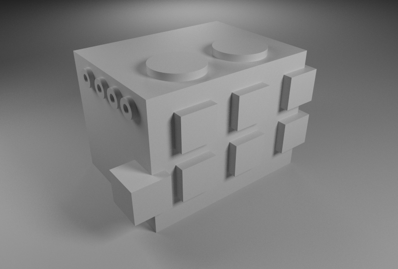
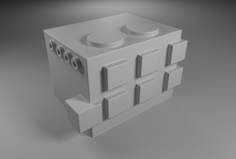
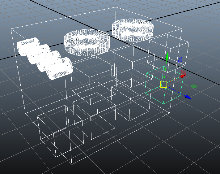
Redshift's Round Corners shading node produces a shading effect that simulates the look of round beveled edges but without introducing extra geometry. It can also work with intersections of objects, as shown in the images below.
| | | |
| --- | --- | --- |
|  |  |  |
| Without round corners | With round corners | Wireframe view of the scene |
## Round Corners Example
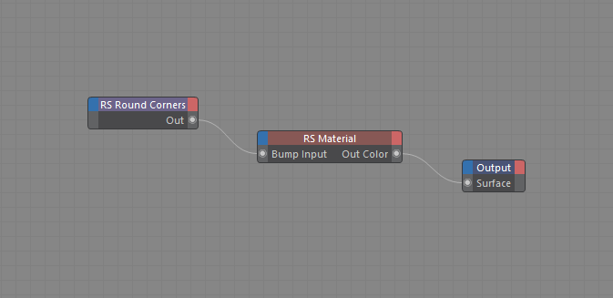
Using the Round Corners node is very simple: all you have to do is connect the node to the lighting shader's 'bump' input, as shown below.
| |
| --- |
|  |
> **Note:** If the object is already using a bump map, you'll need to use Redshift's [Bump Blender](https://help.maxon.net/c4d/en-us/Content/html/COM_REDSHIFT3D_REDSHIFT4C4D_NODES_CORE_BUMPBLENDER.html.md) to combine your existing bump map with the round corners node.
| |
| --- |
| 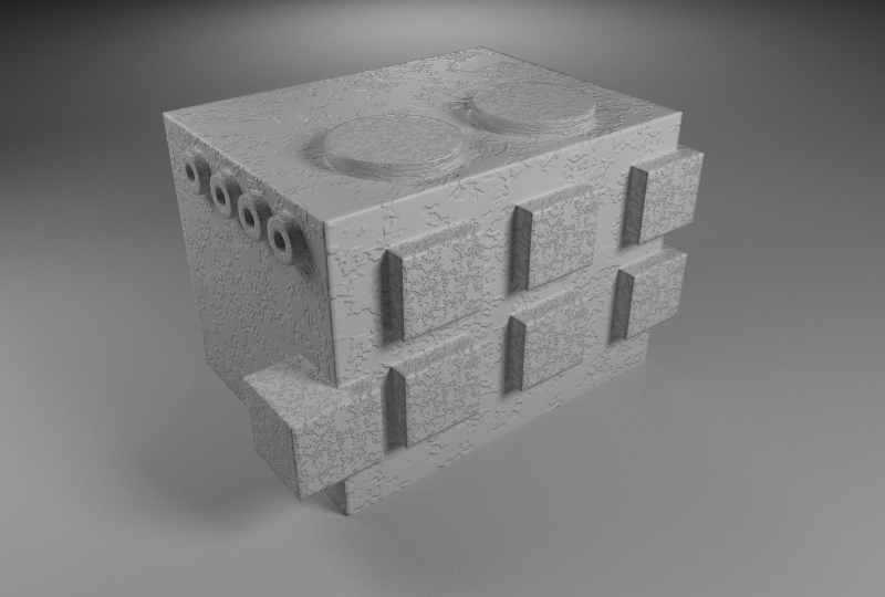 |
| And here's the result! |
## Artifacts and Limitations
Since the Round Corners shading node is essentially a shading trick, there can be cases where it will fail. Here we explore the most common problematic cases.
### Effect of radius
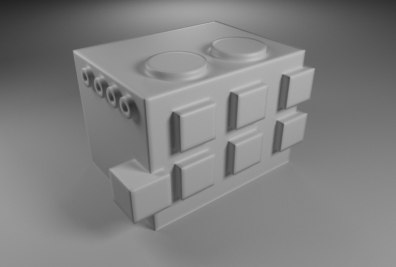
When the radius setting is pushed too much, the resultant image will exhibit artifacts that have to do with the number of samples or with lighting. Below we see how the low (default) num samples produce what appear to be triangular artifacts.
| | | |
| --- | --- | --- |
| 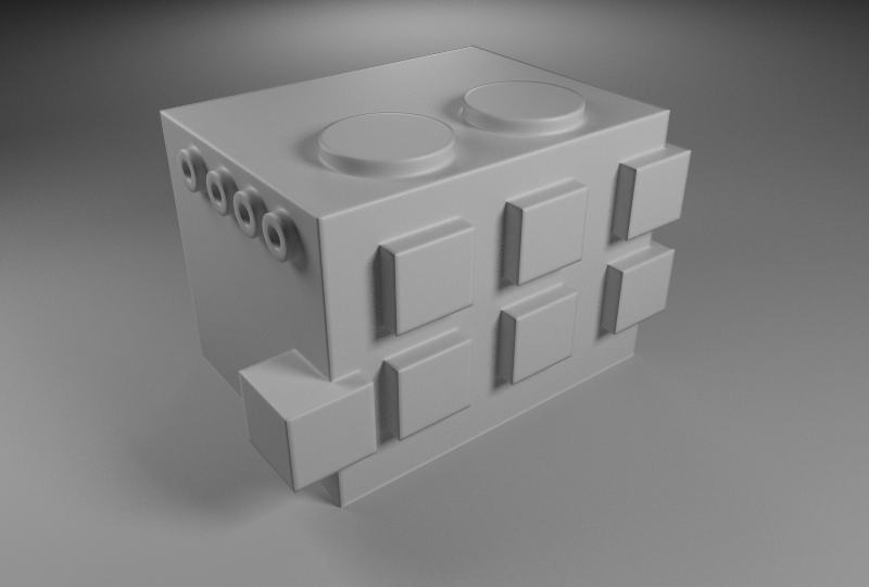 |  |  |
| Radius 0.05.
Looks ok. | Radius 0.1.
Some small artifacts appear near corners. | Radius 0.3.
Visible triangular artifacts near the corners. |
The triangular artifacts can be helped with a larger 'num samples' setting. However, even then, a large radius setting creates a situation where the lighting/reflection rays are 'rounded' but are getting blocked by the mesh which still has sharp corners and edges! When this happens some edges might not look rounded, as shown below.
| | |
| --- | --- |
|  | 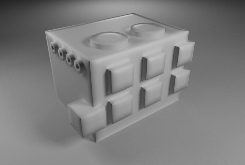 |
| 6 samples | 32 samples
Helps but some edges still don't look 'round' |
If you bump into this issue, switching to traditional beveling methods might be a better choice for your scene or object.
Another issue that can happen with round corners is with intersecting objects producing 'inner' (hidden) or near-coplanar polygons.\
In the following example the hidden sides of the cubes are 'tricking' the round corners algorithm into thinking that there are corners there.
| | |
| --- | --- |
| 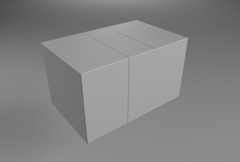 | 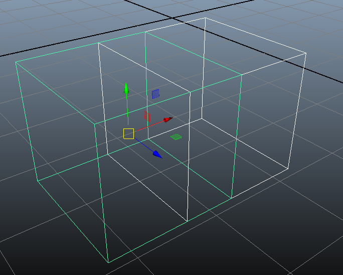 |
| Inner (hidden) polygons producing false edges | Two cubes, exactly side-by-side |
The only solution in this case, is to delete the hidden polygons or boolean the objects together.