Optisch
Choose how you would like to use the following parameters:
- EV only: Sensitivity (ISO), Aperture (f/#) and Shutter Time/Shutter Angle will not affect the exposure of the rendering. This way you can use these settings to just control Depth of Field and Motion Blur. To brighten or darken the rendering, use the Exposure (EV) value.
- Filmic: Sensitivity (ISO), Aperture (f/#) and Shutter Time/Shutter Angle will work a with a regular still or movie camera and not only control Depth of Field or Motion Blur, but also the exposure of the rendered image.
Belichtung
Belichtung (EV)[-100.00..100.00]
You can use this value to multiply the amount of light in your scene. A value of 0 will keep all light intensities untouched. An Exposure (EV) of 1 will double the intensity of the light in the scene, while an Exposure (EV) of -1 will cut all intensities in half.
In previous versions of Redshift, this setting was known as Photographic Exposure and a part of the PostFX section of tools.
Empfindlichkeit (ISO)[0.00..+∞]
This value describes the sensitivity of a negative film or camera sensor to light. In real-life high ISOs mean that the film is very sensitive and will capture a lot of light in a short amount of time, but the image can be grainy. Low ISOs mean that the shutter has to be open for longer for the film to capture enough light (otherwise the image will be too dark) but the final result will be cleaner. Please note that Redshift does not simulate the chemical properties of film or the noise of an image sensor, so there will be no problems with grain at high ISO settings! This value is only available for Exposure Type "Filmic".
Use this value to prevent colored light sources (e.g., sky, sun, candles, etc.) from colorizing white surfaces. Set the White Point color to the color of the light source's color.
Note that you can also use this parameter to color your rendering, by using the Color Wheel input to choose the complimentary color. For example, a bluish color will result in a warm colored rendering.
Not supported with fisheye, orthographic, spherical, or cylindrical camera projection.
In real-life, light has to travel through a camera lens before it reaches the film or sensor. Lenses are often imperfect and, depending on the angle of the lighting, they might absorb or reflect away some light so less of it eventually reaches the camera. The result is darkening around the edges of the image. This imperfection, however, can sometimes be visually pleasing and 'focuses' the viewer towards the center of the image. The higher the Vignetting value, the more darkening there will be around the edges of the image.
|
|
On the left, rendering without the vignetting effect and on the right the same scene with vignetting. |
Schärfentiefe
These settings mainly let you control the transition between in focus and out of focus elements in your rendering.
This value is only used if the Bokeh option is active.
The Focus Distance, measured from the camera's origin out (= film or sensor plane), defines the spacing to a plane that lies perpendicular to the angle of view, on which all objects are displayed perfectly in focus. In front of and behind this plane, all surfaces are rendered progressively blurred, based on the Aperture (f/#) value.
The Focus Distance can be defined interactively with the mouse in the Viewport by clicking and dragging on the camera's center front handle, or you can activate the Picker icon next to the Focus Distance and click on the surface in your viewport that should be in perfect focus. The distance towards the clicked position will be entered to the Focus Distance field automatically.
|
|
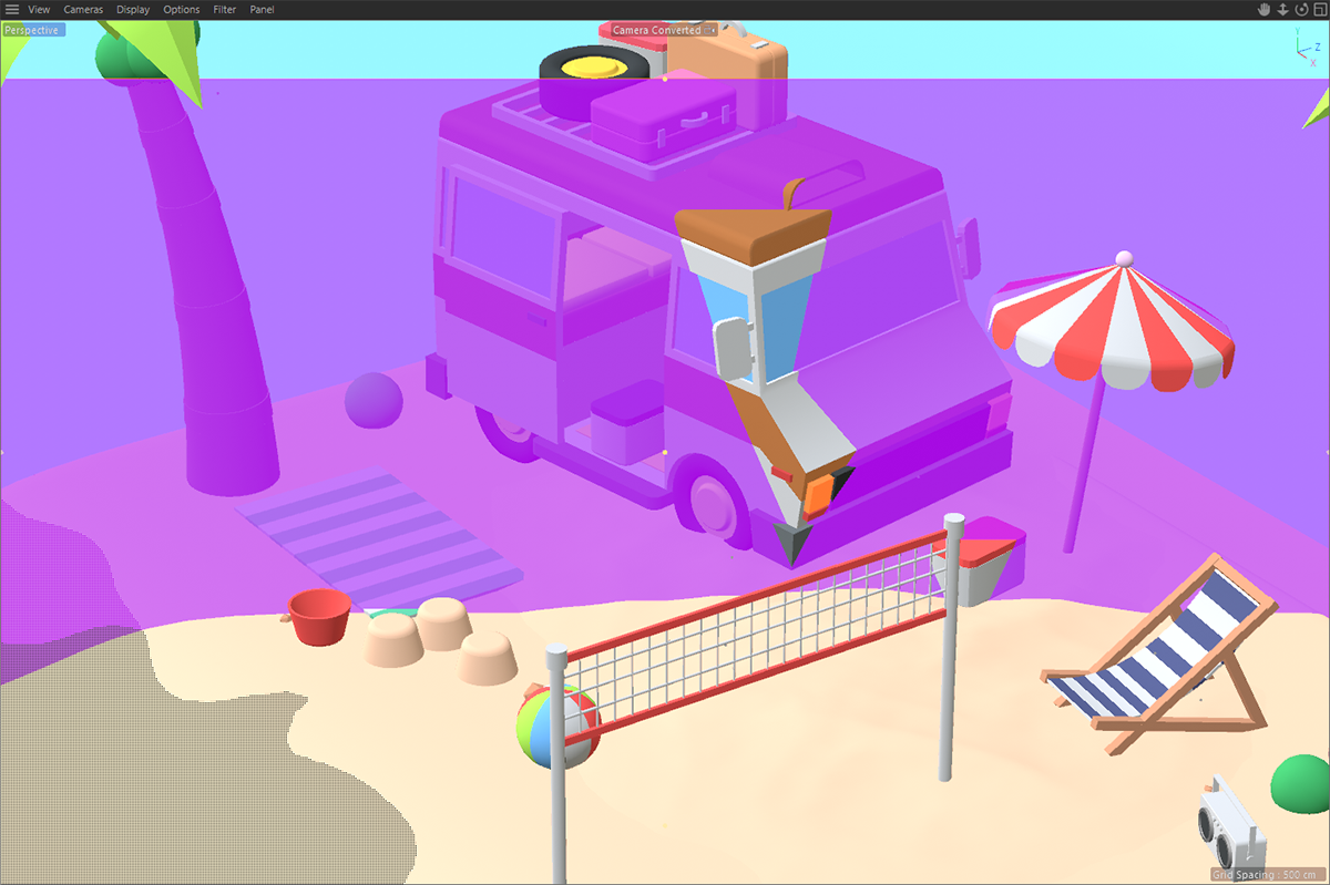
The Focus Distance plane can also be made visible in the viewports by activating "Focus Plane" in the "Display" tab of the camera. Here it was colored dark purple. |
The Focus Distance can be defined interactively with the mouse in the Viewport by clicking and dragging on the camera's center front handle, or you can activate the Picker icon next to the Focus Distance and click on the surface in your viewport that should be in perfect focus. The distance towards the clicked position will be entered to the Focus Distance field automatically.
Instead of entering a value for the Focus Distance you can also link to any object here, by dragging an object from the Object Manager to this field. The distance between the camera position and the position of the linked object will be used as Focus Distance. This is especially usefull for example during animations, to keep a specific position in focus, even if the camera is moving. You can also use an animated Null object to drive the Focus Distance.
When using the Object link field to use the position of an object as Focus Distance, you can manually tweak this Focus Distance by entering an Offset value.
The Aperture value (F-stop) is used to adjust the focal aperture. The larger the focal aperture (i.e. the smaller the Aperture value), the smaller the depth of field will be and vice-versa. So in short, smaller Aperture values result in stronger blur for surfaces that are further away from the Focus Distance plane. If the Exposure Type 'Filmic' is enabled, Aperture (f/#) will also define the amount of light that can enter the camera. Smaller values will then result in brighter renderings.
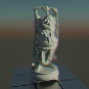
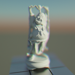
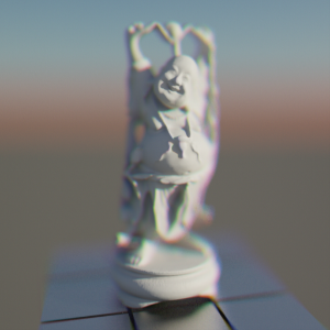
All blurry effects based on the Focus Distance and the F-Stop value are only calculated, if the Bokeh option is active!
Activate this option to calculate blurry effects for out of focus elements in your scene.
|
|
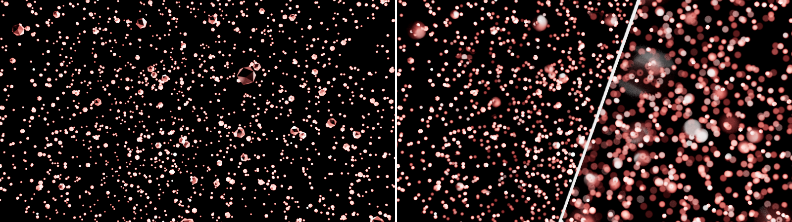
On the left you can see the original scene, rendered without the Bokeh effect. The two images on the right show the same scene, this time with active Bokeh calculation. The change between the two images on the right is just caused by different F-Stop values. |
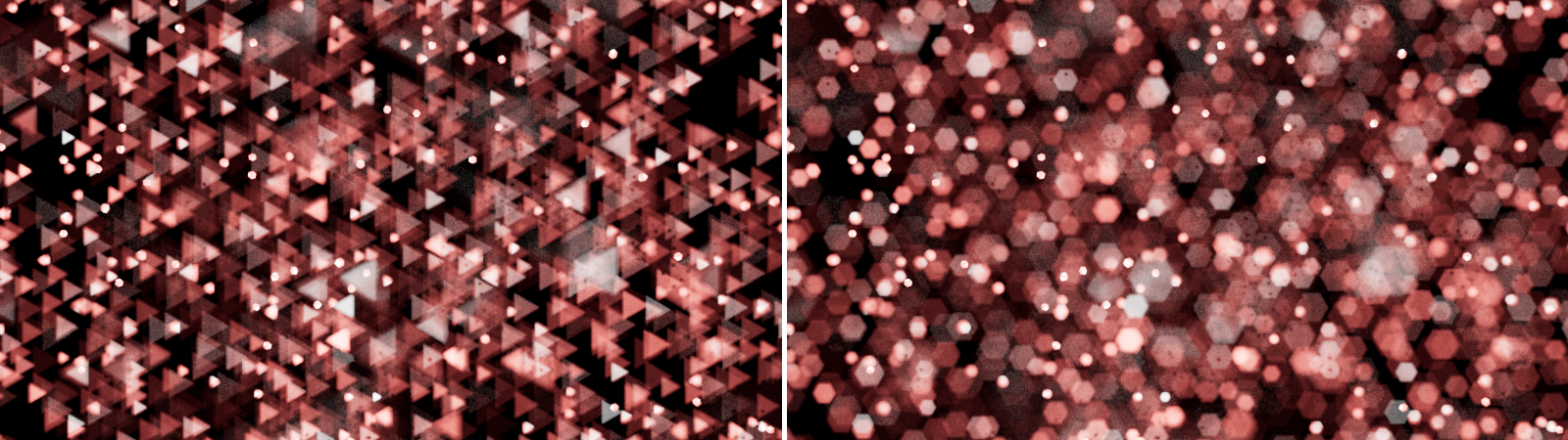
Ideally, the aperture of a camera lens corresponds to a circle. This results in surfaces lying in the blur appearing magnified in a circle. This can be observed particularly well on small, bright areas, such as those created by highlights or intense reflections.
In reality, however, the aperture opening is shaped by individual blades that allow the aperture size to be changed. You control this size via the Aperture (f/#) value. By using blades, the perfect circular shape can only be approximated, depending on how many blades are installed. Accordingly, the use of 6 blades, for example, results in a hexagonal opening rather than a circle, and the areas lying in the blur are displayed hexagonally enlarged.
If this approach is pursued further, arbitrarily shaped apertures would also be conceivable in principle, which would then also lead to correspondingly shaped blurs.
These three options, a perfect circle, an aperture limited by straight blades, and an arbitrarily shaped aperture, are also available on the Redshift camera by choosing between the modes Circular, Bladed and Image.
This parameter can squash the depth-of-field effect and simulate the effect observed on anamorphic lenses. Values below 1 stretch the bokeh vertically, values above 1 stretch the bokeh effect horizontally. A value of 1 preserves the original proportions of the bokeh effect.
|
|
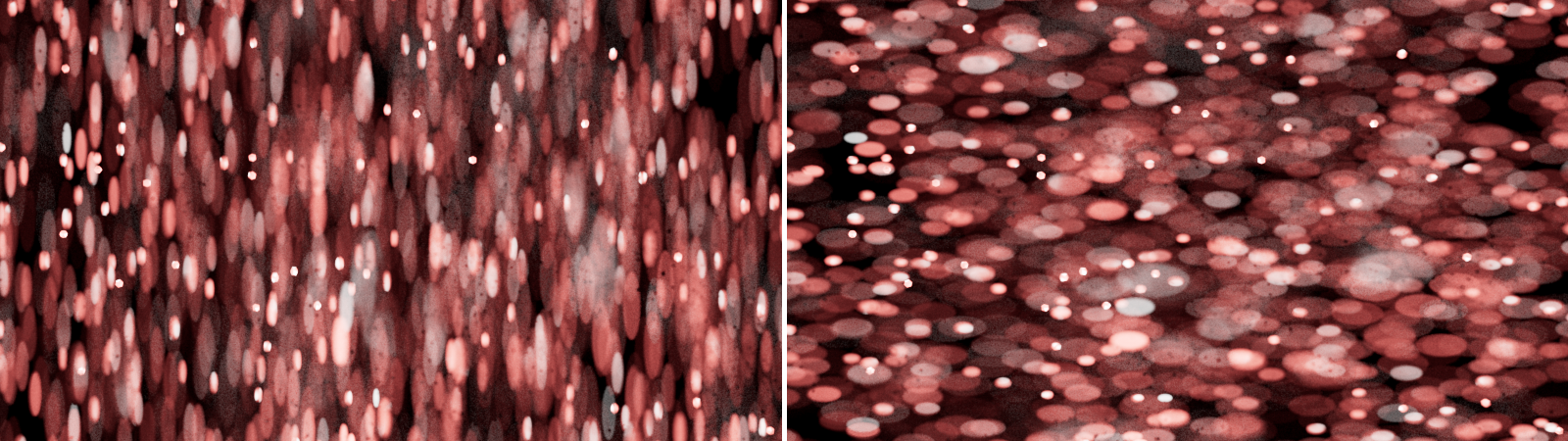
The image on the left shows Bokeh with an Aspect of 0.5, while the right image is rendered with an Aspect of 1.5. |
Sphärische Aberration[0.00..+∞]
With this value you can influence the brightness distribution within the bokeh spots. With small values, the brightness is concentrated more in the center of a bokeh spot. With larger values, on the other hand, the center can remain dark and the outer border of each bokeh spot appears particularly intense. The following images demonstrate this for three-sided bokeh (3 blades).
|
|
The image on the left shows a small value for Spherical Aberration, resulting in a centered brightness. With larger values, the outer borders of the Bokeh appear brighter than the center. |
This setting is only available for Diaphragm Bladed and sets the number of blades for the simulated aperture opening. The images below show possible results, using different amounts of blades.
|
|
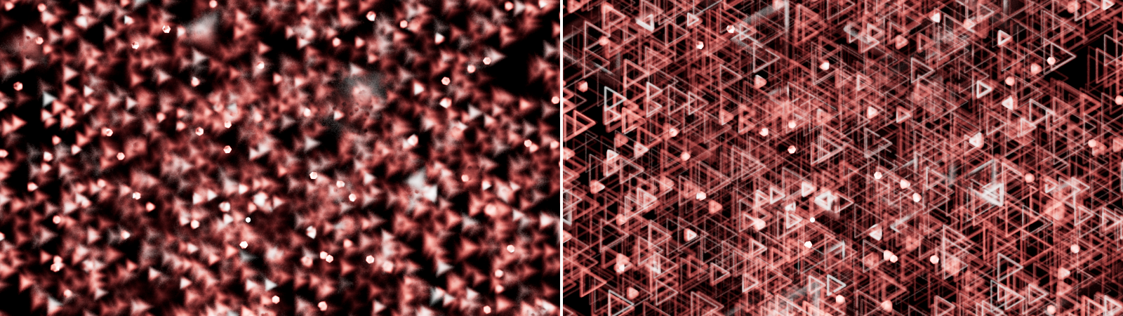
The image on the left was rendered with three blades, the image on the right uses six blades. |
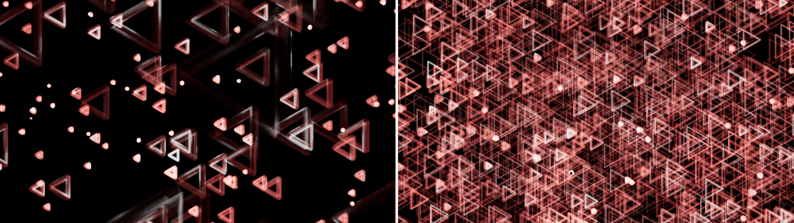
Note that the orientation of the bokeh shape changes depending on the position relative to the plane of focus. The bokeh shapes that lie behind the plane of focus are calculated mirrored vertically and horizontally. This also corresponds to the real representation of bokeh in traditional photography or filming.
|
|
The image on the left shows only the Bokeh effect between the camera and the Focus Plane. The right side shows the Bokeh effect behind the Focus Plane. The Bokeh shape appears mirrored there. |
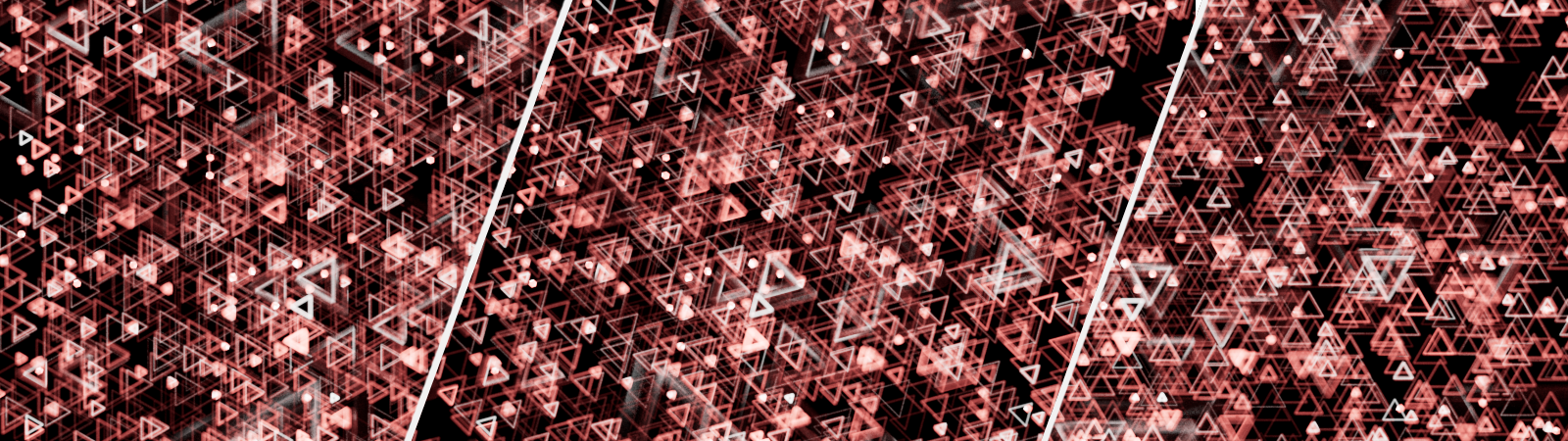
This value allows you to rotate the Bokeh shape in Diaphragm Blades mode. Take note, that to direction of rotation is different for the Bokeh shapes in front of the Focal Plane (counterclockwise) compared to the Bokeh shapes behind the Focal Plane (clockwise).
|
|
From left to right these images show Bokeh with three Blades, using a 0°, a 45° and a 90° Angle value. |
When using Diaphragm Image you can use this input to load a bitmap. A loaded image can be a simple black and white mask to shape the Bokeh effects, as shown in the image below.

|
|
In this example, a bitmap with a white heart shape on a black background was loaded as an Image and shapes the Bokeh effects. |
As you can see in the images above, the loaded image is used mirrored along the vertical and horizontal direction when used on the Bokeh effects located behind the Focal Plane.
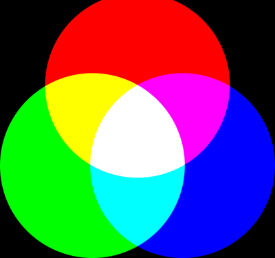
Real-life camera lenses sometimes also exhibit an artifact called "chromatic aberration". Chromatic aberration means that, depending on the angle of the light reaching the lens, certain light wavelengths (colors) are reflected away and never reach the sensor or film. This creates a rainbow effect which is stronger in parts of the image that are out-of-focus. This kind of effect can also be recreated by using an Image for Bokeh, as you can see below.
|
|
Images likes this one can be used to simulate chromatic abberation. |
This setting determines how to handle the colors and brightnesses of the loaded image. For example, if a colored image as shown above were used to simulate chromatic aberration, the parts of the rendering in focus should still remain neutrally colored.
To get a neutral result in the focused pixels one would have to draw this picture perfectly. I.e. there should be exactly the same number of red pixels to blue to green. Not doing so would mean that the image would either be too red or too green or too blue and also too dim.
But drawing such an image is almost impossible to do! So, for that reason, Redshift offers several Normalization modes to balance out the different colors of a loaded image:
- Off: The loaded image is used as it is. If all used colors don't add up to "white", the rendered Bokeh will be darker and you might see a color shift in the rendering due to the different amounts of red, green and blue pixels in your loaded image.
- Sum to White: If you want to ensure that the colors you use all add up to white, use this mode.
- Unit Intensity: This is the right mode, if the overall tint is not white, but you still want the final image to not be any darker than it would normally be.
The colorful bokeh image shown above actually suffers from several issues. It contains black, so it means that it doesn't sum to white. Also the red/green/blue circles are not perfect: the red circle has its top chopped off, so there is less red in this image compared to the green and blue pixels. But using the normalization modes, this image can still be used without issues!
|
|
|
| Normalization: Off The in-focus pixels are tinted and look darker |
Unit Intensity The image is brighter but there is still tint because of the red circle being chopped off (so green and blue 'win'). |
Sum to White The image is now normalized so that all its pixels add up to white. This removes any unwanted tinting in the in-focus pixels |
Bewegungsunschärfe
The shutter determines the time period in which light falls into the camera or onto the sensor. There are two different concepts for specifying this exposure time:
- Still: This is the classic behaviour of digital still or movie cameras. The shutter speed is specified in fractions of a second ('Shutter Time'). The 'Shutter Offset' is defined in fractions of a second.
- Movie: On traditional film cameras, the shutter is formed by a disc rotating in time with the frame rate. Inside this disk is an opening whose size is specified by the 'Shutter Angle'. This concept takes care, that the shutter is always in sync with the current frame rate so changing the frame rate will always result in a correct shutter speed for animations. The 'Shutter Offset' is defined in degrees too.
Verschlusszeit (s)[0.02..8000.00]
This parameter controls the duration the camera's shutter will stay open in Still mode. A value of 30 means 1/30, i.e. a 30 th of a second. Therefore, the smaller the value, the longer the shutter stays open. In combination with the Filmic Exposure Type, using a longer Shutter Time will result in a brighter rendering. On the other hand, a longer Shutter Time also results in more blur for moving objects, if the cameras Motion Blur option has been activated.
This setting is available in Movie mode. Movie cameras use a rotating shutter disc, that is doing a full 360° rotation for every recorded frame. This rotating disc has an opening to allow light to enter the camera. The Shutter Angle defines the size of the opening relative to the 360° rotation. A 180° Shutter Angle in combination with a 30 fps recording would result in a 1/60 of a second shutter time (1s/30fps * 360°/180°). Changing the frame rate will always provide a correct shutter speed for animations. Used for filmic exposure and motion blur. With Filmic Exposure, larger Shutter Angles will result in brighter renderings.
Since cameras always capture and evaluate light through the sensor over a certain period of time, blurring occurs on objects that move relative to the camera during the exposure. The intensity of this motion blur depends on the relative speed of the objects and the exposure time. These options are available:
- Off: No Motion Blur will be calculated during rendering
- Render Settings: The global Render Settings are used for Motion Blur.
- Override: The camera's settings for Motion Blur are used. Motion Blur must still be enabled overall in the Render Settings.
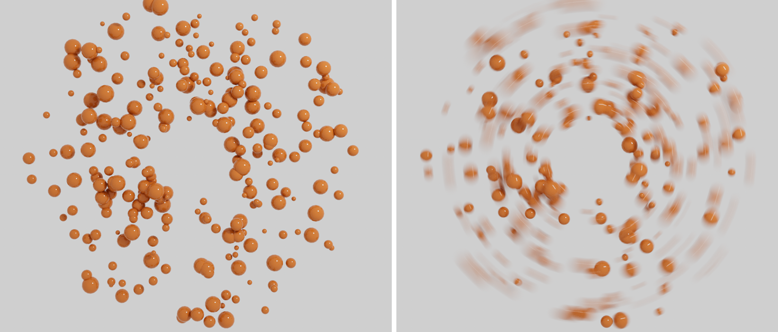
|
|
On the left are spheres with individual velocities moving on circular paths. Without Motion Blur, this motion cannot be seen in a still image. On the right you see the same image, only this time rendered with Motion Blur. The different speeds of the spheres are clearly visible. |
Take note, Render Settings offer additional controls for the calculation of Motion Blur and Motion Blur must be enabled there for rendering as well!
By using the Redshift Object Tag individual Motion Blur settings can be applied on a per object basis if needed.
Motion Blur is not visible while rendering in the standard viewports or while rendering with Live or IPR. You have to render to the Picture Viewer or do a final render in the Redshift Render View.
In real-world conditions, motion blur occurs whenever something moves relative to the camera. For example, imagine you are sitting in a train filming the landscape out the window. Although the landscape itself is still, your images will contain motion blur because the camera has moved relative to the landscape during the exposure. If you only want to see motion blur when the objects you are rendering are themselves in motion, turn this option off.
|
|
Both images are rendered with motion blur, showing rotating spheres as seen from a camera that is passing by. The left side shows how the motion of the camera and the motion of the spheres add up, when 'Camera Motion' is active. With this option switched off, only the motion of the spheres is evaluated for the motion blur calculation (right image) |
This offsets the opening and closing of the shutter and can be useful for matching footage or for fine tuning the motion blur, e.g. in particle situations or animations. In Still mode, you specify a fraction of a second here. In Movie mode, you specify an angle at which the rotating shutter disk is to be rotated.
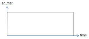
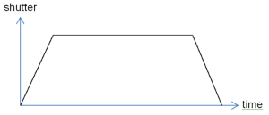
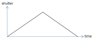
Real-life camera shutters don't open instantaneously – they open gradually. The Efficiency parameter controls how fast the shutter opens. A setting of 1.0 means the shutter will open instantaneously, while a setting of 0.0 means that it will open as gradually as possible. The images below show how the Efficiency parameter affects the shutter opening speed.
|
|
|
|
Efficiency: 1 |
0.3 |
0 |
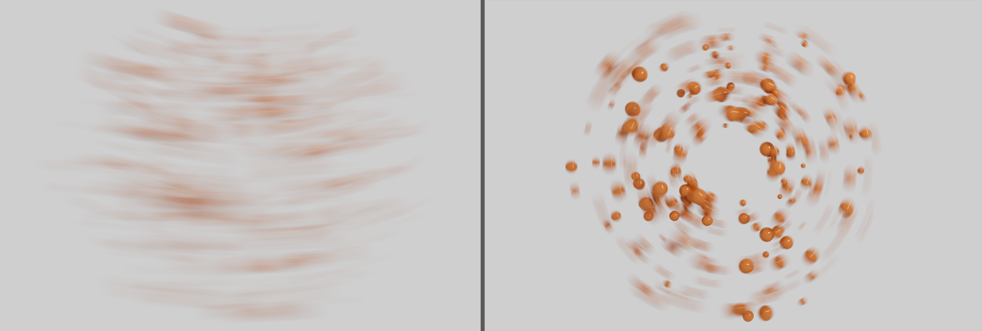
The Efficiency parameter affects the look of motion blur trails, as it will be shown in the example pictures below. The smaller the Efficiency is, the softer the motion blur trails will appear.
|

|

|
| Efficiency: 1 | 0.7 | 0 |
Distortion
Due to their lens geometry, real-life cameras tend to distort the captured images. If the user needs to add CG elements to real-life (distorted) camera footage, the CG elements will also have to be distorted. To be able to control this effect, activate this option and load an RGB image to the Image slot.
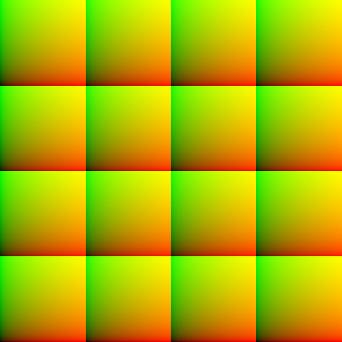
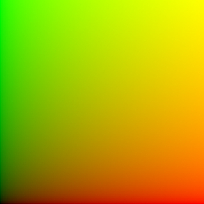
The distortion is calculated by UV coordinates, projected onto the rendered scene. The U direction is represented by the color red (1, 0, 0) and the V direction is represented by the color green (0, 1, 0). Therefore an image that wouldn't add any distortion to the rendering will look like this:
|
|
The calculation of distortions is based on an image that shows UV coordinates, by using red for the U direction (horizontal) and green for the V direction (vertical). |
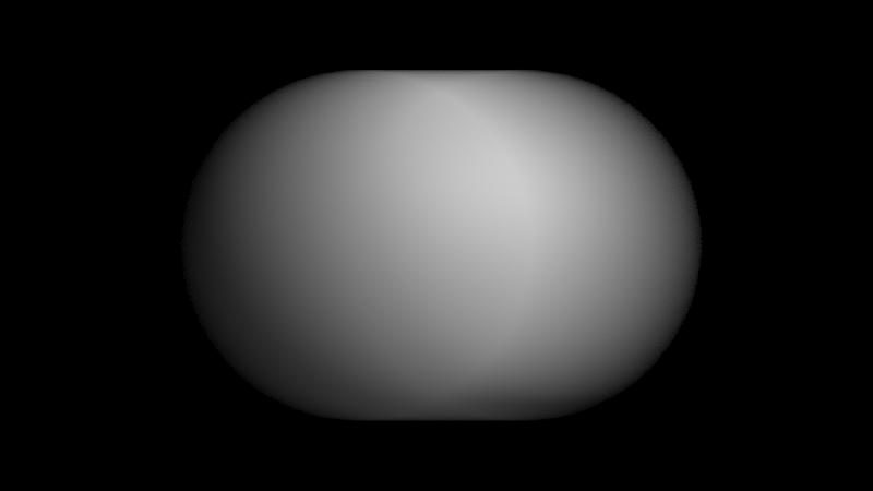
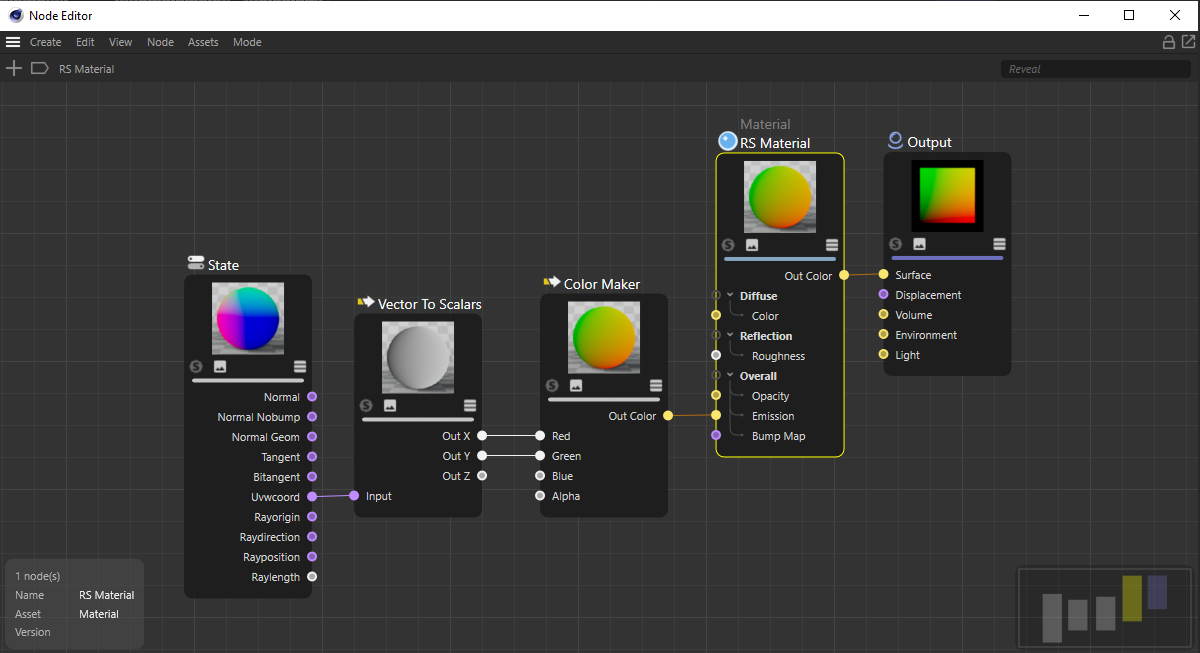
This type of image can easily created in Redshift by rendering a UV gradient on a plane. To achieved this use a State node and connect the "Uvwcoord" output to a Vector to Scalars node which then passes the "Out X" and "Out Y" to a Color Maker's "Red" and "Green" channels as seen in the example image below.
|
The following section offers a possible workflow to create your custom distortion map in Cinema 4D.
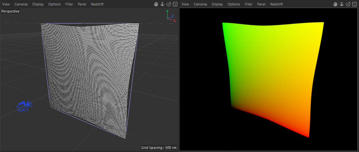
By using a simple plane primitive with our UV gradient material, we can now use any kind of deformation on this plane to distort the representation of the gradient. Be sure to deactivate any Reflection or Diffuse shading in the gradient material and use the calculated UV colors to set the Emission of the material. This prevents any additional shading of the colors on the plane object. Finally place a new camera in front of the plane and use an orthographic perspective for it (such as Front if the plane is in -Z Orientation).
The example below is using two Bulge deformation objects to distort the plane, but any other deformation or even manual sculpting with a tool will work as well. Just take care to adapt the cameras position and Angle of View values before rendering, so that the distorted plane is filling the complete rendering. No background should remain visible.
|
|
Create a Plane primitive and adjust its segment count, so is can be easily deformed and apply the UV gradient material to it. |
When saving a UV Distortion image make certain to save it in Linear Color Space, so no Gamma curve is applied!
|
|
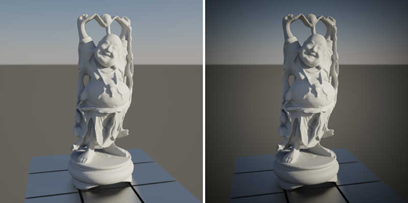
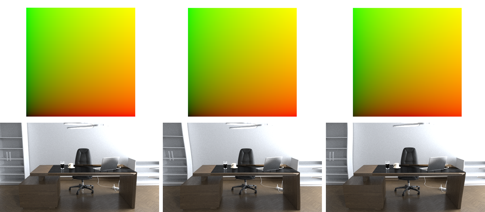
The left image shows the result after rendering with the standard distortion gradient and delivers the same result as rendering with 'Distortion' switched off. The two other renderings show the effect of using a negative and a positive strength. The example gradients only show very subtle differences, but the effect on the render is much more noticeable. |
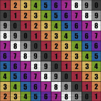
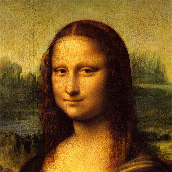
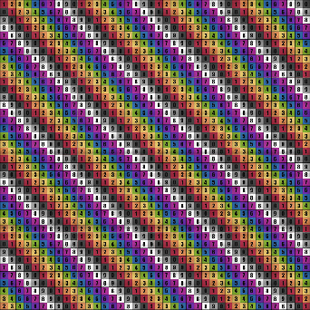
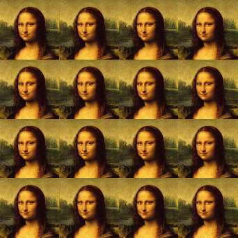
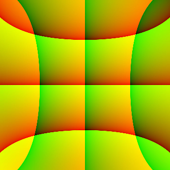
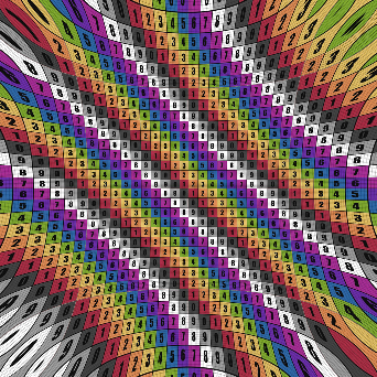
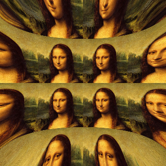
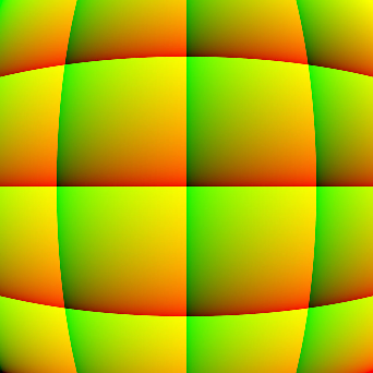
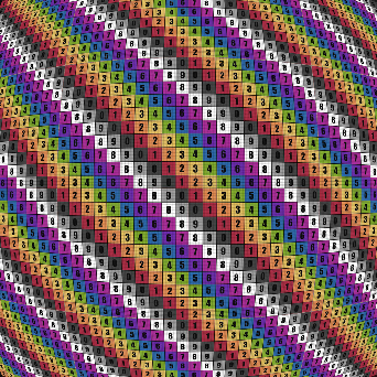
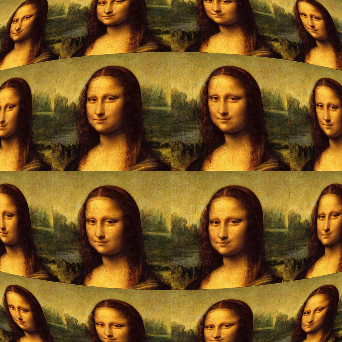
Using the same principle, even more complex distortions can be achieved as demonstrated in the following images. By repeating the standard red/green UV gradient several times in the loaded distortion image, the scene will also be arranged multiple times in the final rendering.
|
|
|
|
| Neutral UV Distortion Image | UV Grid Rendering | Image Rendering |
|
|
|
|
| UV Distortion Image | UV Grid Rendering | Image Rendering |
|
|
|
|
| UV Distortion Image | UV Grid Rendering | Image Rendering |
|
|
|
|
| UV Distortion Image | UV Grid Rendering | Image Rendering |