
This page may include unlocalized contents
Standard Material
Table Of Contents
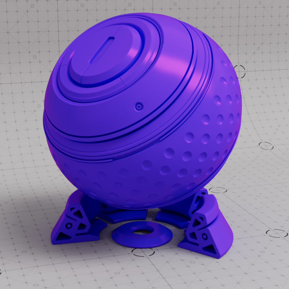
This Standard Material is the recommended all purpose material that is physically plausible, energy conserving and aligned with 'PBR' based principles. It is the successor to the Redshift Material but offers a cleaner interface that is more comparable to the standard material shaders of other render engines.
|
|
| A Standard Material in the Node Editor |
The Standard material supports thin walled translucency in the form of diffuse transmission by interpreting an object's surface as an infinitely thin shell. This simulates light passing through thin objects and is a perfect effect for things like paper or leaves where an object has no actual thickness but needs the look of subsurface scattering without the performance impact.
In the example images below the addition of thin walled translucency allows sunlight to pass through the leaves and the shadows cast by other leaves block the light from passing through the leaves giving them a much more realistic look.
|
|
|
| Leaves with Thin Walled Translucency | Leaves without Thin Walled Translucency |
| Example model from PolyHaven by Rico Cilliers: Potted Plant 02 | |
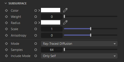
The Standard Material changes the way translucency is handled compared to the legacy Redshift Material. Instead of having a separate "back-lighting / translucency" section like the legacy Redshift Material, the Standard material uses the subsurface component and relies on "Thin Walled" being enabled in the Geometry section — this also disables multiple subsurface scattering and other subsurface scattering parameters with the exception of subsurface color and weight as pictured below.

|
Another key difference between the Standard and legacy RS Material is the addition of energy conservation. The legacy Material allowed more light to be reflected back than was actually present in the scene but the Standard material fixes this, a different approach is required when dialing in the look as it is possible for translucency to completely knock out the diffuse component which does not happen with the legacy Material.
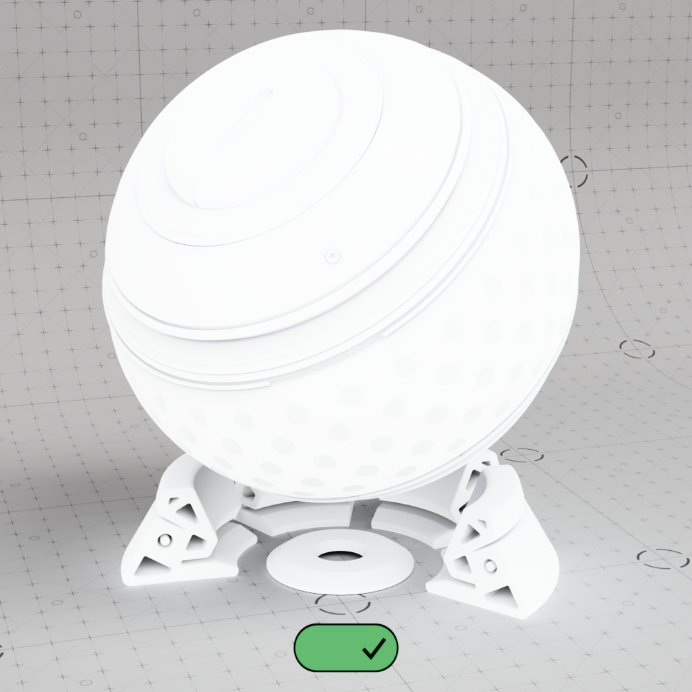
When thin walled is enabled, subsurface color and weight can effectively be thought of as the translucency color and weight from the legacy Material, but now a subsurface weight of 1 will completely disable diffuse shading. This can be seen in the example images below where the Standard material has a base color (diffuse) of red and a subsurface color (translucency) of blue.
|
|
|
|
| Subsurface Weight: 0 Base Color: Red Subsurface Color: Blue |
0.5 | 1 |
At a Subsurface Weight of 1 the leaves might look okay from the back with light shining through them but issues become apparent when seen from the front since shadows are no longer caught on the surface due to the complete lack of a diffuse component.
|
|
|
| Subsurface Weight: 1 |
1 |
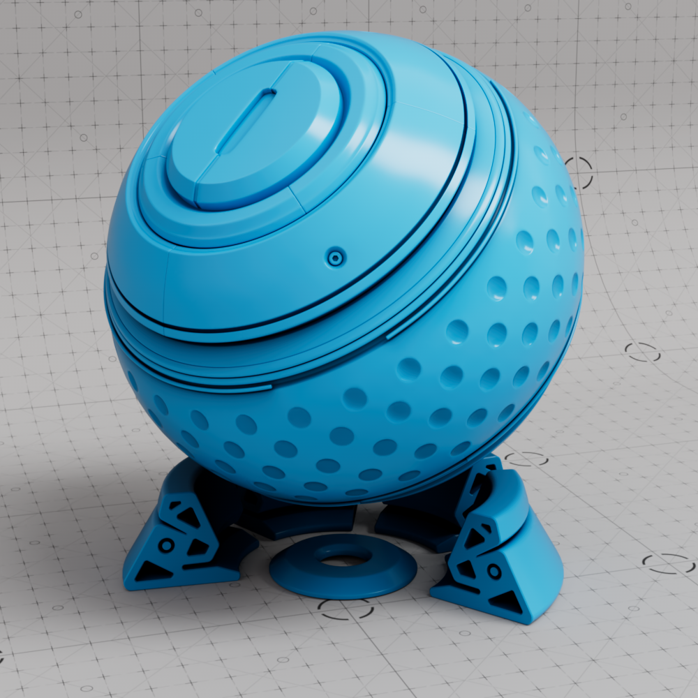
This can be balanced out by decreasing the subsurface weight which reintroduces diffuse shading but still allows light to pass through. Of course, if the results are now too dark you can always use a color correct node to increase the brightness of a texture for the base color or subsurface color.
|
|
|
| Subsurface Weight: 0.5 |
0.5 |
The most common material settings are found in the Base Properties section which is broken up into the following subsections:

|
Here you will find the settings for the diffuse properties of the surface.
This defines the color of the surface for diffuse direct lighting or indirect global illumination. Setting diffuse color to black results in no diffuse lighting.
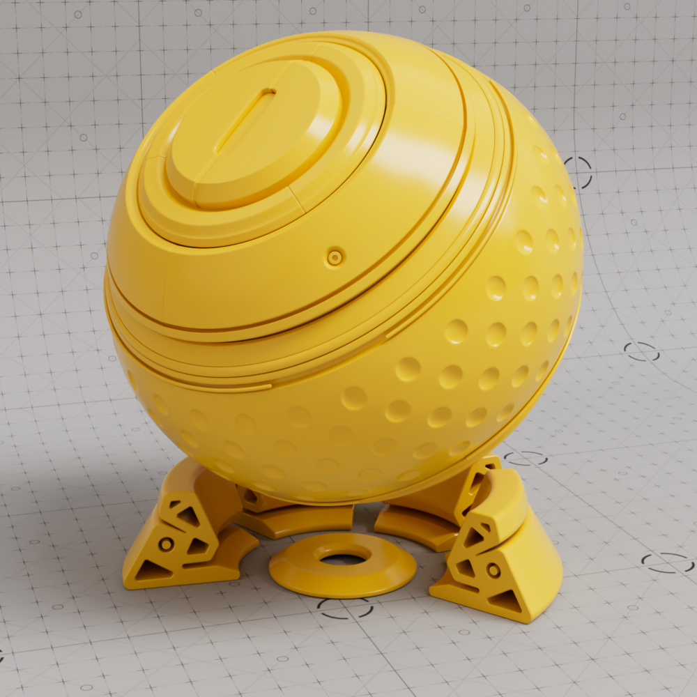
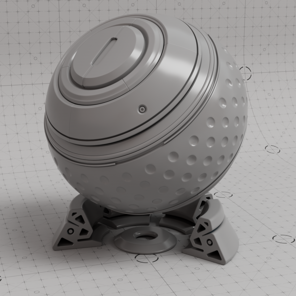
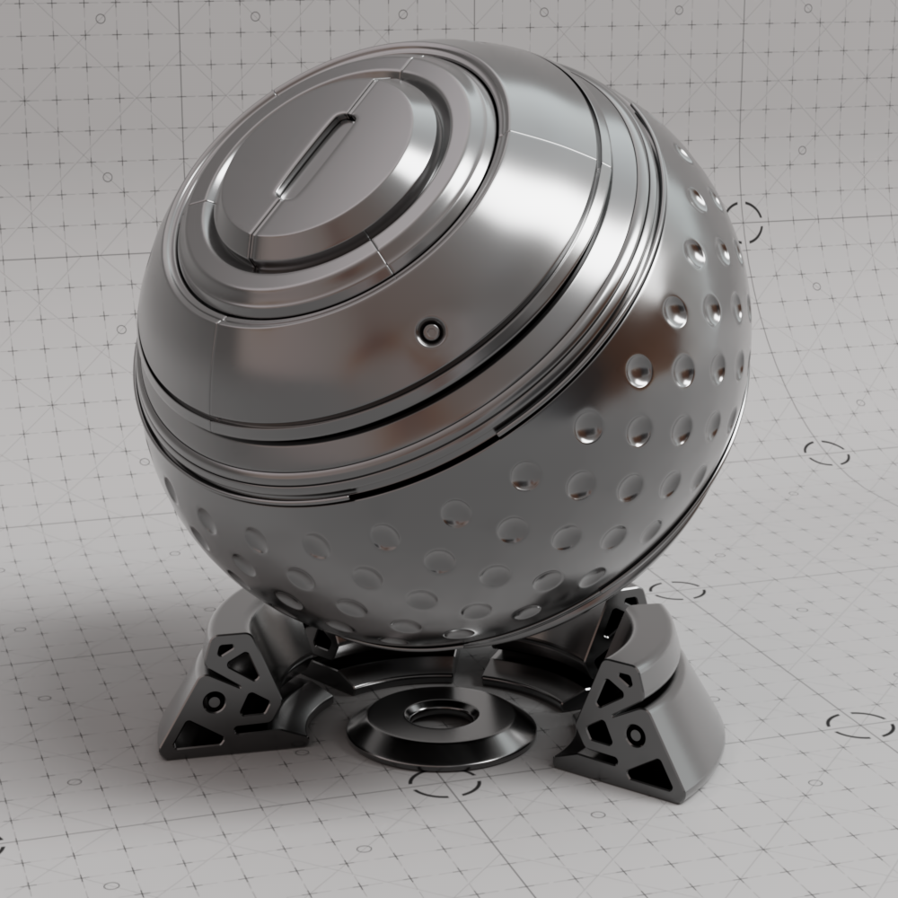
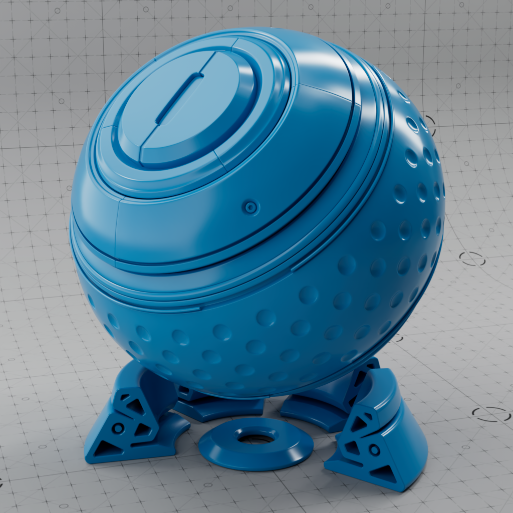
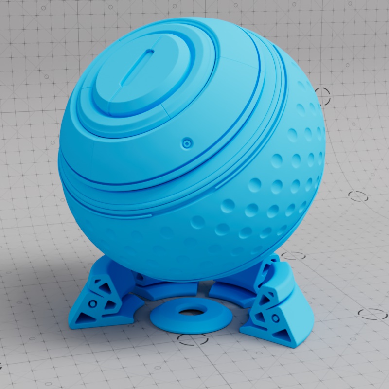
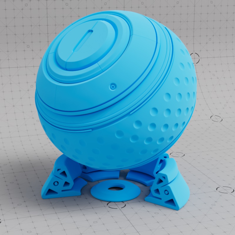
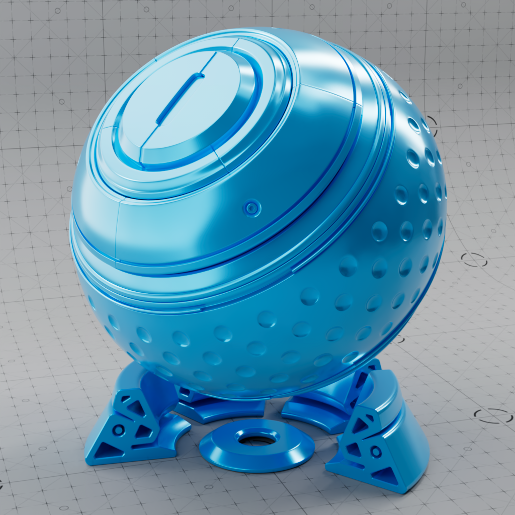
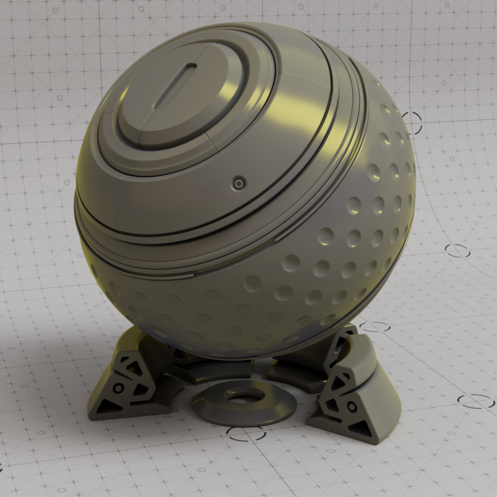
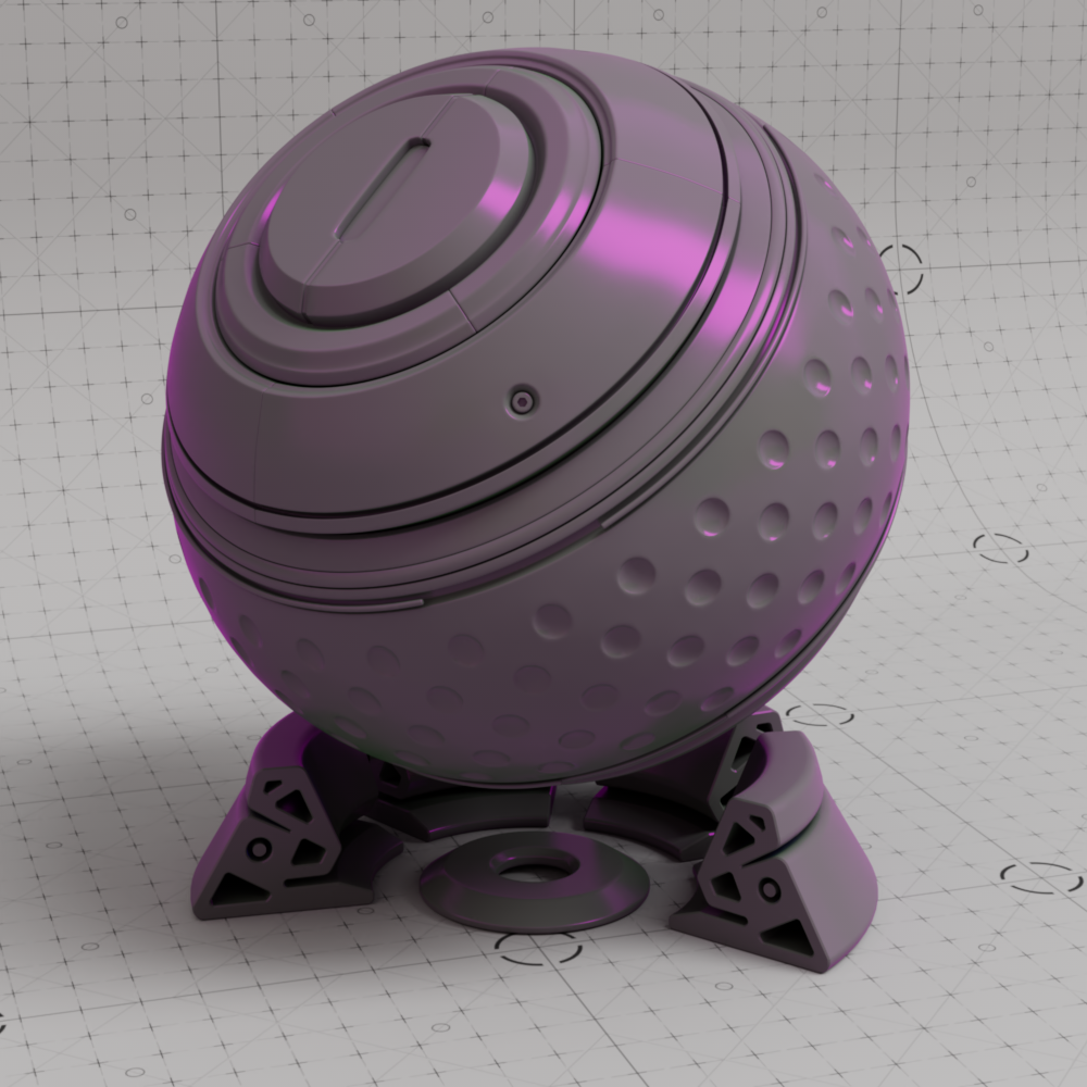
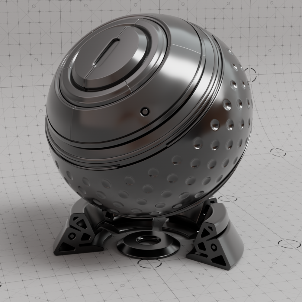
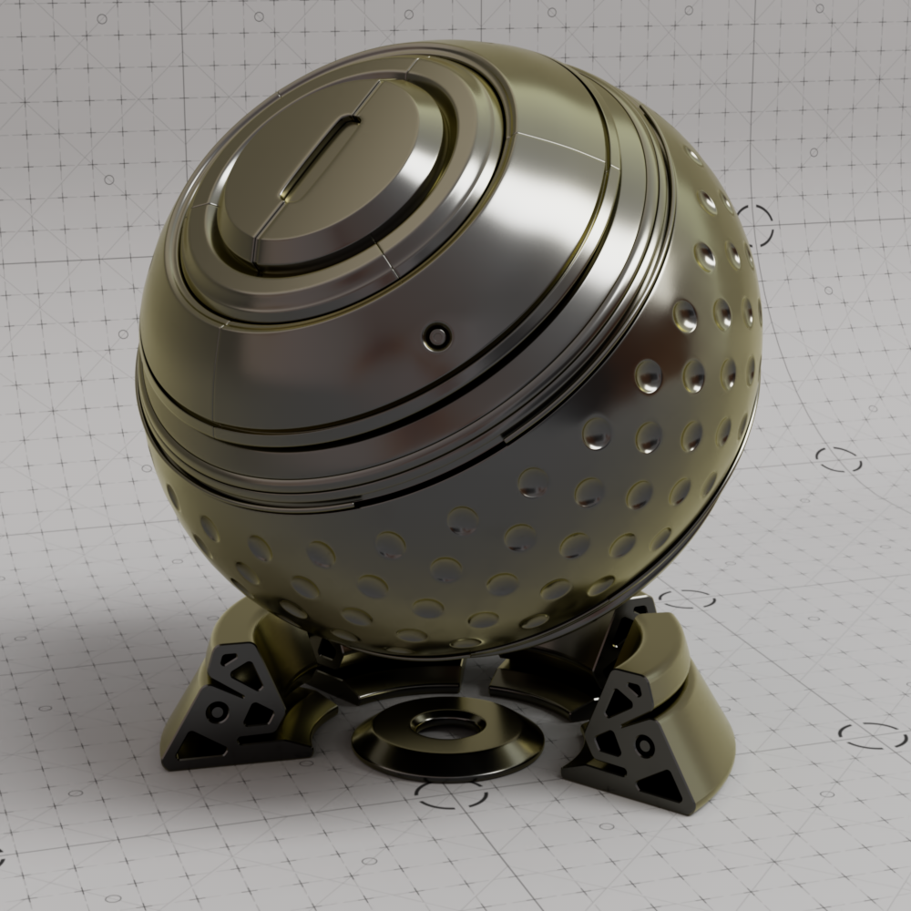
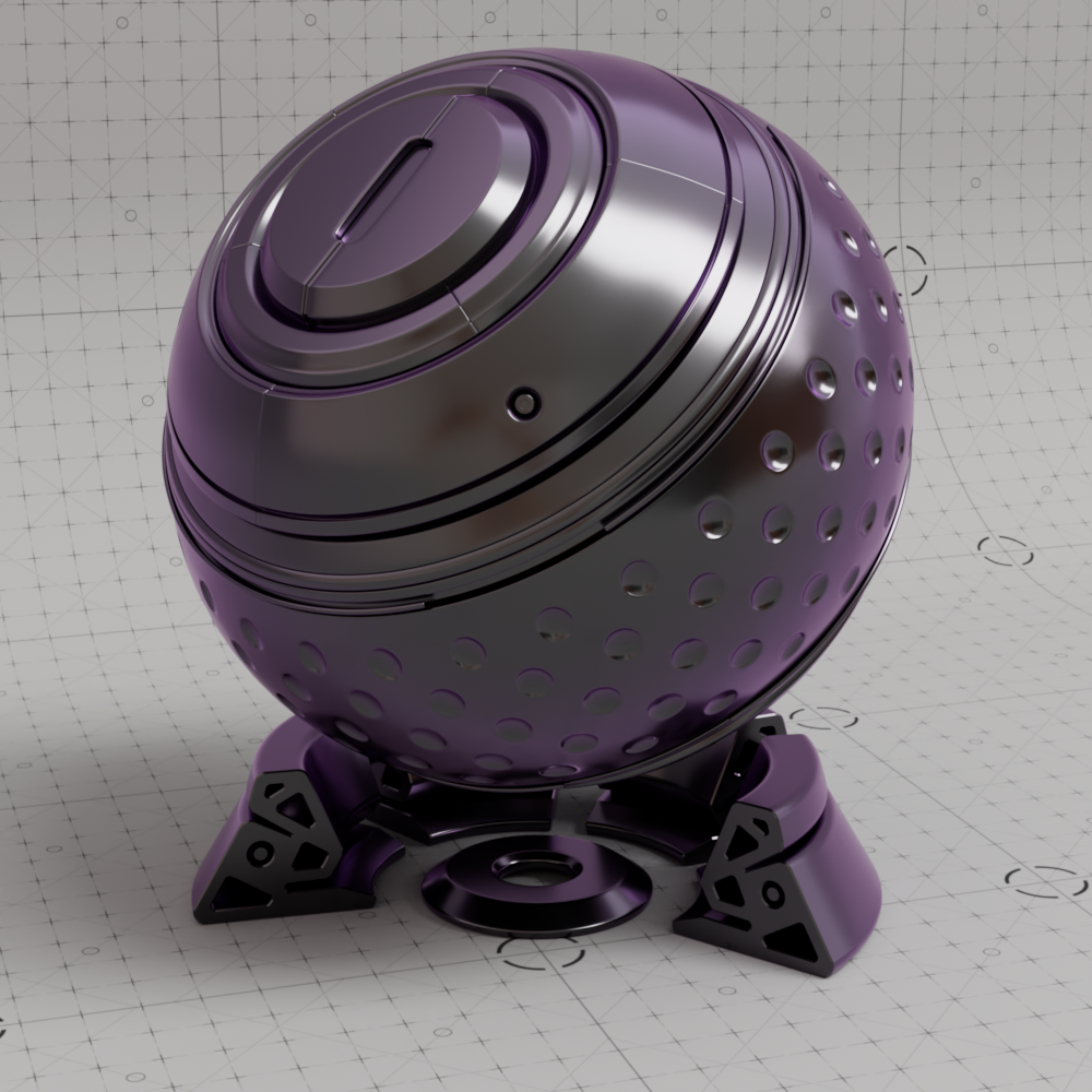
When Metalness is set to a value above 0 the base color controls the color of the metallic reflections as seen in the examples below. Note how a black base color disables all shading when used with metalness but it only knocks out diffuse shading when used without metalness.
Credit to Rich Nosworthy for the Redshift shader ball and scene used in many of the example images on this page.

|
|
|

|
| Base Color: Light Blue Metalness: 0 |
Yellow | Grey | Black |

|

|
|

|
| Base Color: Light Blue Metalness: 1 |
Yellow | Grey | Black |
This scales the overall amount of diffuse lighting, with 0.0 resulting in no diffuse and 1.0 resulting in maximum diffuse.

|
|

|
| Base Weight: 1.0 | 0.5 | 0.0 |
The Diffuse Model determines how the diffuse illumination on the surface is evaluated and thus how the brightness gradients on the surface are calculated. Two models are available:
Note, EON and ON look identical in with a Diffuse Roughness of 0, it is only with higher roughness where the difference becomes apparent.
|

|
|
| Oren-Nayar (default) Diffuse Roughness: 0 |
EON | d'Eon Lambertian Spheres |
Requires Oren-Nayar or EON Diffuse Model.
This controls the roughness of the diffuse lighting and is useful for simulating matte/dirty surfaces. A roughness of 0.0 is equivalent to a perfectly smooth surface, traditional Lambert shading.
With a Diffuse Roughness of 0, Oren-Nayar and EON look identical. However, when Diffuse Roughness is increased EON stays brighter because it preserves more energy — note the brighter secondary bounce on the underside of the ball. This results in EON having a higher contrast between light and shaded areas. When textured the difference is even more noticeable, with EON demonstrating a more nuanced falloff between regions of differing roughness.
| Diffuse Roughness: 0 Diffuse Model: Oren-Nayar vs EON |
1 |
Textured |
Controls the metalness weight with a range from 0.0 and 1.0, where 0.0 is a dielectric material that uses the Reflection settings to control the reflectance and 1.0 is a fully reflective metal material. When metalness is used Base Color controls the primary color of the metal and Reflection Color controls the edge tint.
Values between 0.0 and 1.0 results in a blend between the two types of material.
An IOR to Metal Tints node can be used with a Standard Material for separate IOR control for the red, green, and blue channels.

|
|

|
| Metalness: 0 | 0.5 | 1 |

|
Most real-world materials exhibit some amount of reflection. The two most visible aspects of reflection are its blurriness (driven by Roughness) and its strength (driven by the Weight and IOR settings).
The Redshift Standard Material uses a GGX BRDF.
Controls the color of reflections on the surface. In most cases this should be left at the default white, but it may be necessary to tint reflections a different color for metals. Reflections are disabled when the reflection color is black.
When using a Metalness workflow, Reflection Color tints the reflections seen on the edges of an object while the Base Color tint the remainder of the reflections that are seen at a facing angle.
In the examples below note the difference in reflection color behavior when metalness is used, on non-metallic surfaces all reflections take on the reflection color while on metallic surfaces only reflections along the edges are tinted. Additionally, a black reflection color completely disables reflections on a non-metallic surface while only the edge reflections are dimmed on a metallic surface.

|
|
|

|
| Reflection Color: White (default) Metalness: 0 Base Color: Grey |
Yellow | Pink | Black |
|
|
|

|
| Reflection Color: White (default) Metalness: 1 Base Color: Grey |
Yellow | Pink | Black |
This is a multiplier of the reflection tint. Reflections are disabled when this value is 0.0.
When using a physically based workflow this should be left at 1.0.
|
|

|
| Reflection Weight: 1.0 (default) | 0.25 | 0.0 |
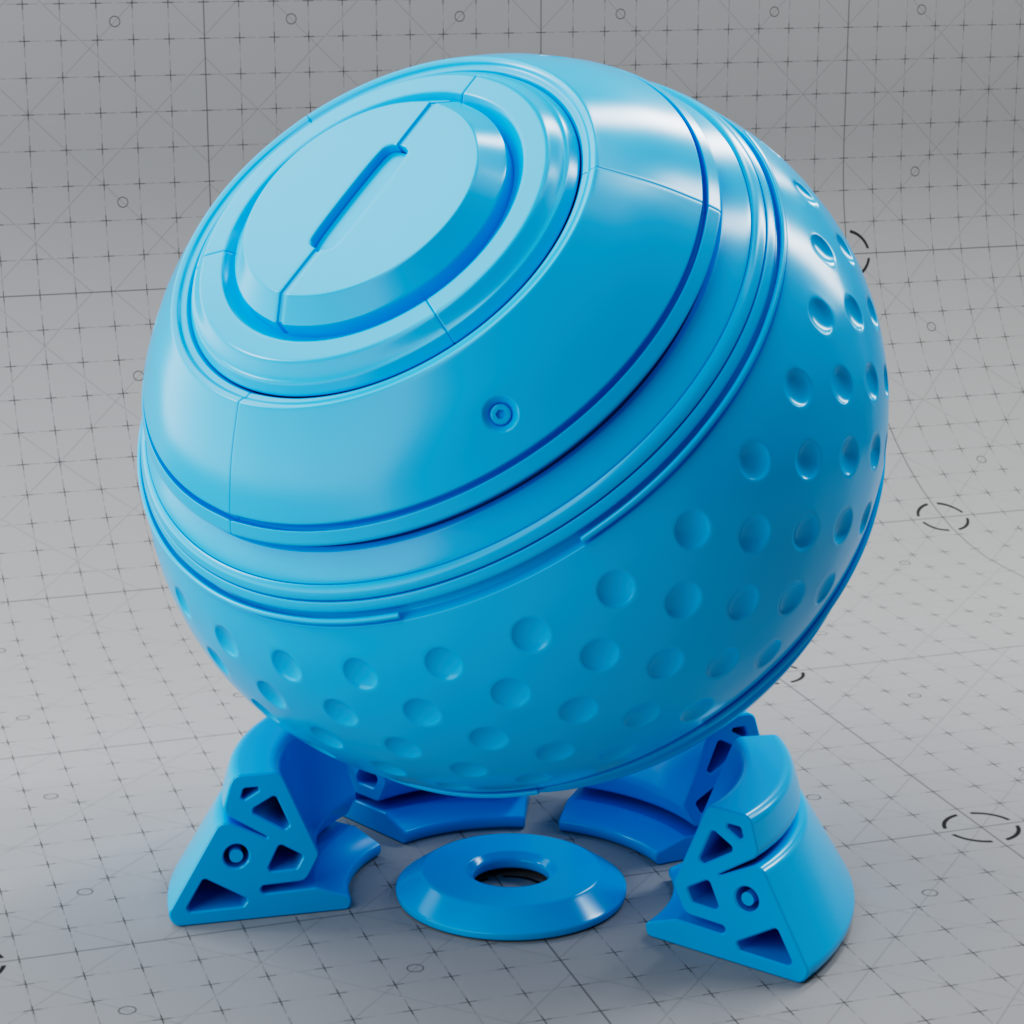
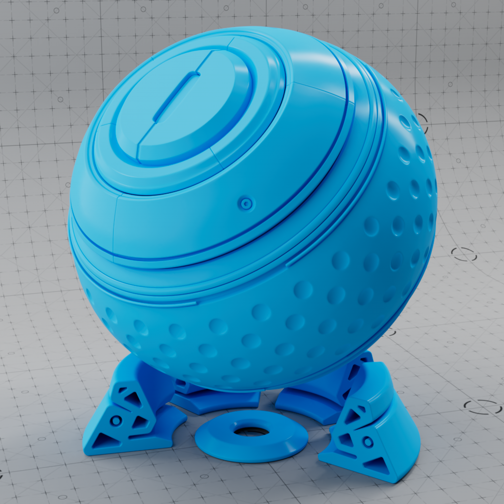
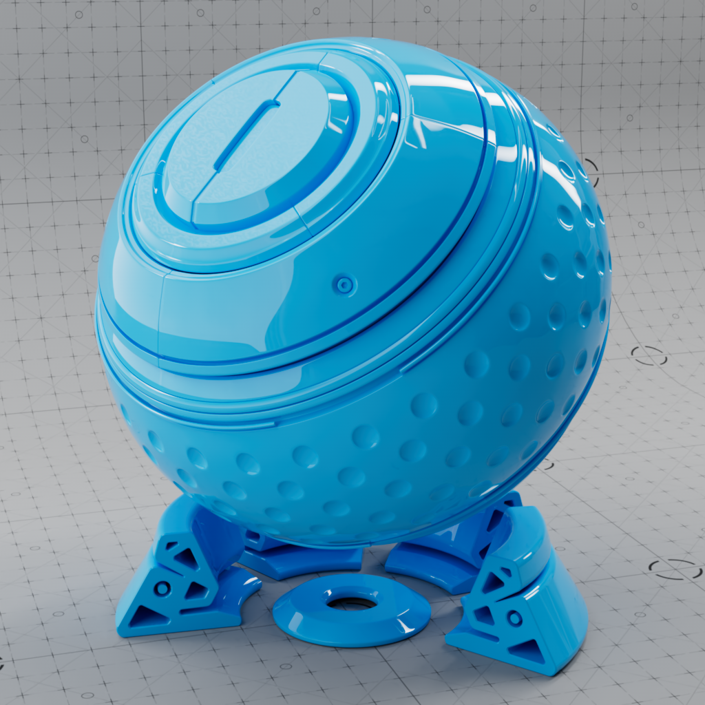
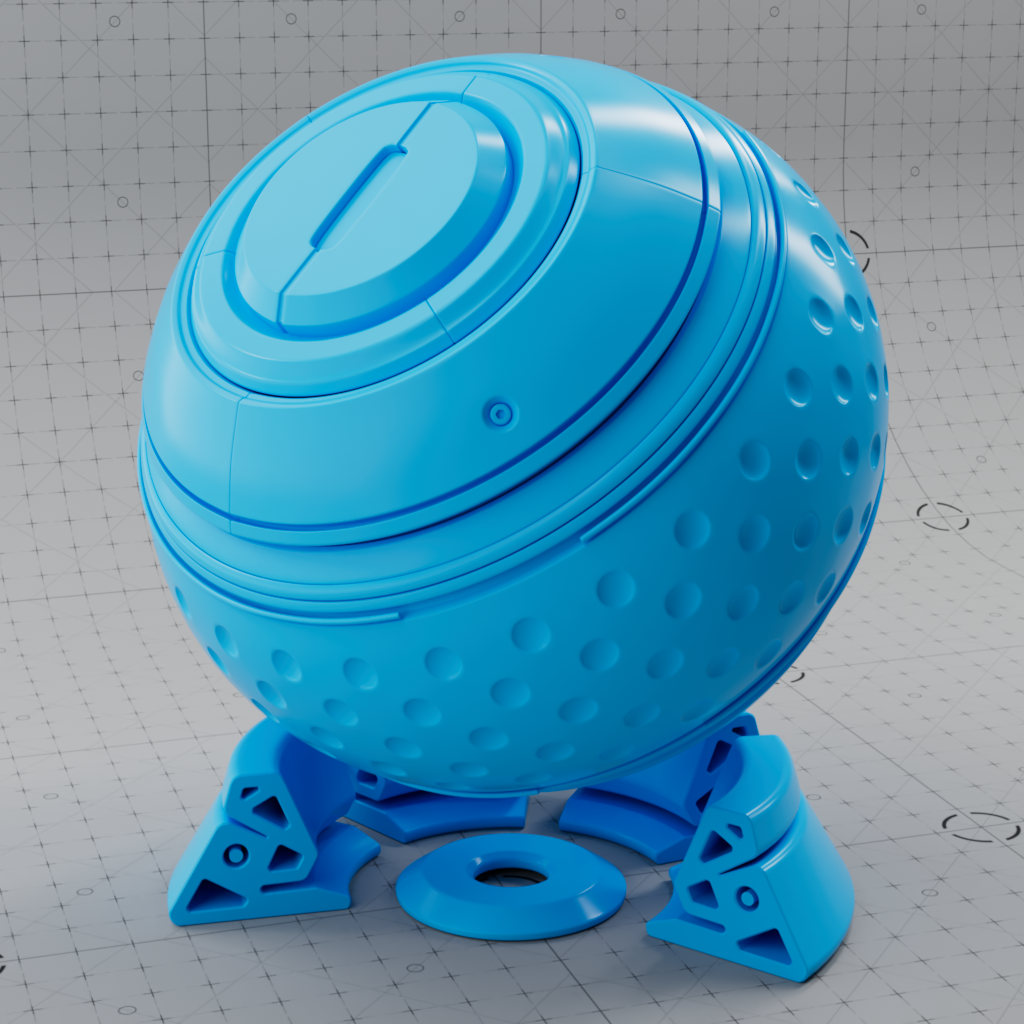
Controls the roughness of the surface reflection. Higher values scatter light in more random directions resulting in blurry reflections, a value of 1.0 results in an almost diffuse appearance. Lower values concentrate the light into sharper and more distinct reflections, a value of 0 results in a perfectly 'polished' surface.
Roughness simulates microfacet surface imperfections or a porous structure by controlling how light bounces off the surface. As roughness increases reflected light scatters all over the scene, simulating a bumpy uneven surface, and therefore less of it bounces back into the render camera which results in a visually dimmer overall reflection. However, the amount of light being reflected is the same, regardless of roughness, due to energy conservation. As roughness decreases the reflected light is scattered less, simulating a very smooth surface, with more of it bouncing back directly into the render camera resulting in brighter and sharper reflections. This is why wet materials tend to look shiny, liquids — which tend not to exhibit any surface roughness — fill in the gaps of an otherwise porous surface creating the appearance of a smooth surface and therefore brighter reflections.
|

|

|

|
| Reflection Roughness: 0.0 | 0.25 | 0.75 | 1.0 |
IOR is short for Index Of Refraction and determines how the light bounces when reflected off of or refracted through a material. As this is a physical based value, you can look up the IOR for a specific material online. Most dielectric materials tend to have an IOR between 1.4-1.6
IOR defines how light rays traverse a medium and bend at each point when changing mediums. A value of 1 is equivalent to how light behaves in a vacuum, resulting in no bending of the light as a vacuum does not interact with the light rays at all. In the real world, normal materials never have an IOR below 1 because that would be impossible since it would mean light travels faster in this medium than it does in a vacuum.
|

|
|
|
| Reflection IOR: 1.25 | 1.5 (default) | 3.0 | 1.0 |
This allows to you stretch reflections in a particular axis. Anisotropy is used to emulate materials such as brushed metals where surface roughness is focused in a particular direction. You have to increase Reflection Roughness above 0.0 to see the effect.

|

|
|
| Reflection Anisotropy: 0 (default) | 0.75 | 1.0 |
Rotates the direction of the anisotropic reflections. Input values range 0 to 1 which is equal to the rotation angles 0° to 360°.
| Anisotropy Rotation: 0 to 1 Anisotropy: 1 |
Blurry reflections (when "Roughness" is greater than 0.0) will need multiple samples to get a clean "grain-free" result. Higher numbers will reduce any potential grain issues, but will take longer to render and vice-versa.
|
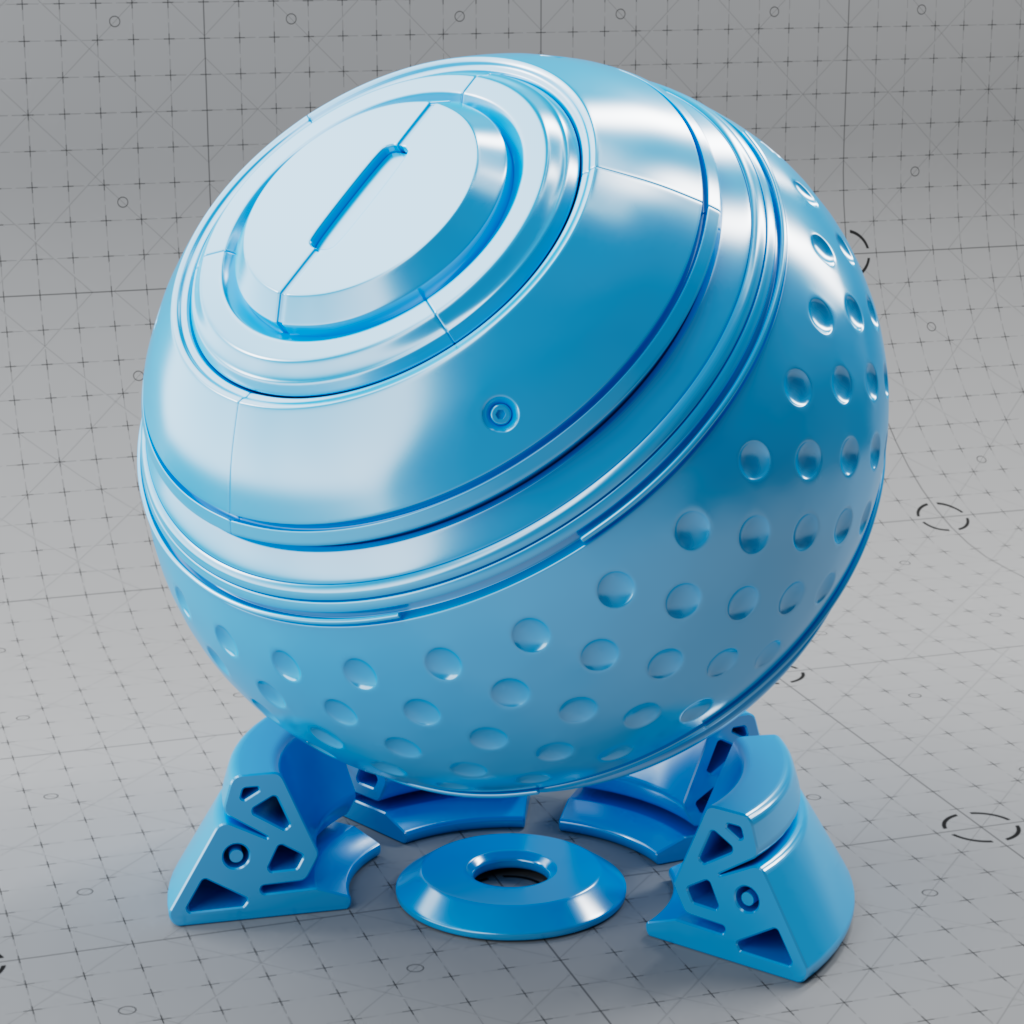
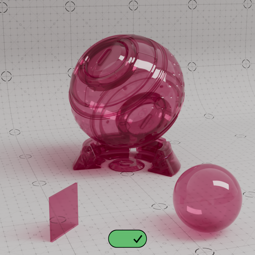
These settings set the refractive transparency of the material. A full refraction calculation needs a double sided geometry. To see refractive tint one a single sided geometry, you have to activate the Thin Walled option in the Geometry section.
A transmissive object's shadow can have a very large impact on the overall look and realism of an object, for information on controlling a transmissive object's shadow please see the Advanced Transmission section.
This is the refraction tint. To be physically correct, when used in conjunction with Subsurface Scattering or Transmission Scatter, this should be white.
|
|
|
|
|
| Transmission Color: White (default) Transmission Weight: 1 |
Green | Orange | Black |
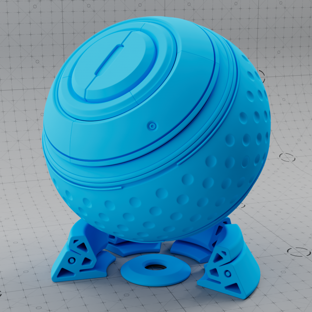
This is a multiplier of the refraction tint. When 0.0 refraction transparency is disabled.
|
|
|
|
|
| Transmission Weight: 1 Transmission Color: White |
0.25 | 0.75 | 0 (default) |
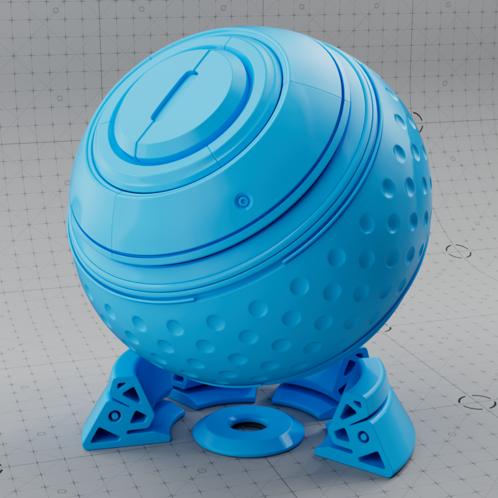
The Extra Roughness parameter allows for transmission roughness that can be higher or lower than Reflection Roughness. This is because the Reflection Roughness parameter also affects the transmission roughness result, how blurry refractions appear.
Extra Roughness can be set from -1 to 1, the default value of 0 results in Transmission Roughness that is equal to Reflection Roughness.
The example images below demonstrate the Reflection Roughness being used to control the transmission roughness.
|
|
|
|
|
| Reflection Roughness: 0 Extra Roughness: 0 Transmission Color: Red |
0.2 (default) 0 |
0.5 0 |
0.75 0 |
Positive or negative values can be used for Extra Roughness to counteract Reflection Roughness so that refractions can be more or less blurry than reflections.
The example images below demonstrate offset values between the two parameters along with the calculated transmission roughness equivalent which is just the difference between Extra Roughness and Reflection Roughness.
|
|
|
|
|
| Extra Roughness: 0 Reflection Roughness: 0 Transmission Roughness : 0 Transmission Color: Red |
- 0.2 0.2 0 |
- 0.4 0.5 0.1 |
0.5 0.2 0.3 |
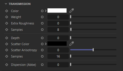
Controls the number of samples used for transmission refractions, higher transmission roughness will need more samples to get a clean "noise-free" result. Higher numbers will reduce grain issues, but will take longer to render and vice-versa.
Fixed Unit: Centimeters
Controls the distance in centimeters a ray needs to travel before the transmission color reaches full saturation. As light travels through a medium, some wavelengths of light get absorbed/attenuated making transmissive objects darker/lighter in regions of differing thicknesses. Therefore, Transmission Depth should be set in accordance with the actual thickness of the object taken into consideration. At higher values, the visual density of the object decreases resulting in less absorption of color in the object.
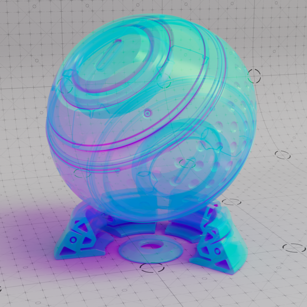
For example, with a transmission color of red, when the depth is low the transmission color is hit early resulting in a rich red color that makes the object look dense — when the ray continues to travel farther than the depth value the transmission color becomes an even darker shade of red until it starts to look black and opaque. On the other hand, if transmission depth is high it will take longer for the ray to reach full saturation, resulting in a desaturated red look in the thinnest parts of an object that make it look more like clear glass. When a depth value of 0 is used the transmission is fully tinted with the Transmission Color at all depths.
In the examples below take note of the different behavior Transmission Depth has when Transmission Scatter Color is black versus grey. At a transmission depth of 0 no scattering takes place and transmission looks the same regardless of the scatter color. When the depth is low and the scatter color is black the object looks dark but clear, however when the scatter color is grey the object looks foggy due to the single-scattering taking place which is an ideal look for plastics. At higher depth values both results begin to converge as the scattering effect becomes less pronounced and the object starts to look glassy again.
|
|
||
| Transmission Depth: 0 (default) Transmission Scatter Color: Black (default) Transmission Color: Red |
0.01 to 1 | 1 to 20 |
|
|
||
| Transmission Depth: 0 (default) Transmission Scatter Color: Grey Transmission Color: Red |
0.01 to 1 | 1 to 20 |
A Transmission Depth value greater than 0 is required for transmission scattering.
Controls the subsurface single scattering component which simulates microscopic particulate suspended in a medium, this is similar to multiple scattering but better suited to thinner volumes. Transmission scattering is useful for controlling subsurface scattering in plastics, thick fluids like orange juice or milk, and large volumes of thin fluids like the ocean to reproduce its typical blue tint.
Lighter colors result in more scattering while darker colors result in less scattering, by default the black scatter color results in no scattering. For more information on controlling the scattering look see the Transmission Depth parameter above.
|
|
|
|
|
|
| Scatter Color: Black (default) Transmission Depth: 1 Transmission Color: White |
Grey | White | Red | Green |
Controls the direction transmissive light is scattered.
The default anisotropy of 0 results in isotropic scattering, when the light scatters equally in all directions. Positive values increase the chance for forward scattering, when more light is scattered in the direction the light rays are already traveling. Negative values increase the chance for back scattering, when more light is scattered back towards the location of the light source.
In the examples below, note how the final result is highly dependent on the location of the light source relative to the transmissive object. All examples showcase a transmission anisotropy from -0.8 to +0.8, positive values frequently lead to a more glassy appearance while negative values lead to a more frosted look.
| Subsurface Anisotropy: -0.8 to +0.8 Front Lighting |
-0.8 to +0.8 Standard Lighting |
-0.8 to +0.8 Back Lighting |
Transmission scattering, like all blurry effects, will need more samples to get a clean "noise-free" result. Higher numbers will reduce grain issues, but will take longer to render and vice-versa.
This value describes how much the refractive index (IOR) in a transparent material varies across light spectrum wavelengths resulting in a color shift in the material. Lower values result in more intense dispersion while higher values result in little to no dispersion. With a default value of 0 dispersion is disabled. Dispersion behaves similarly to a roughness effect so it can add extra noise to the scene.
Typical values start at 10 for glass and around 70 for diamond, in general higher quality materials exhibit lower amounts of dispersion.
|
|
||
| Dispersion: 0 (default) | 0.01 to 1 | 1 to 5 |
|
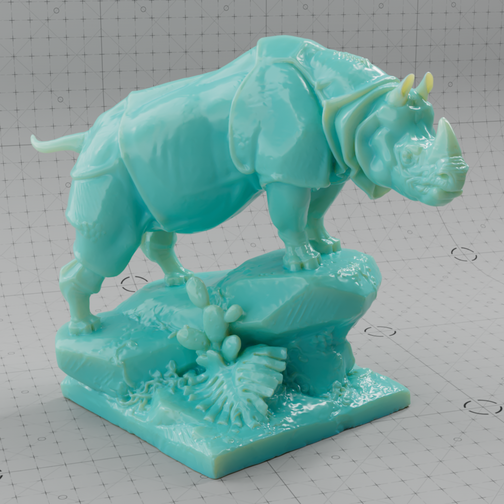
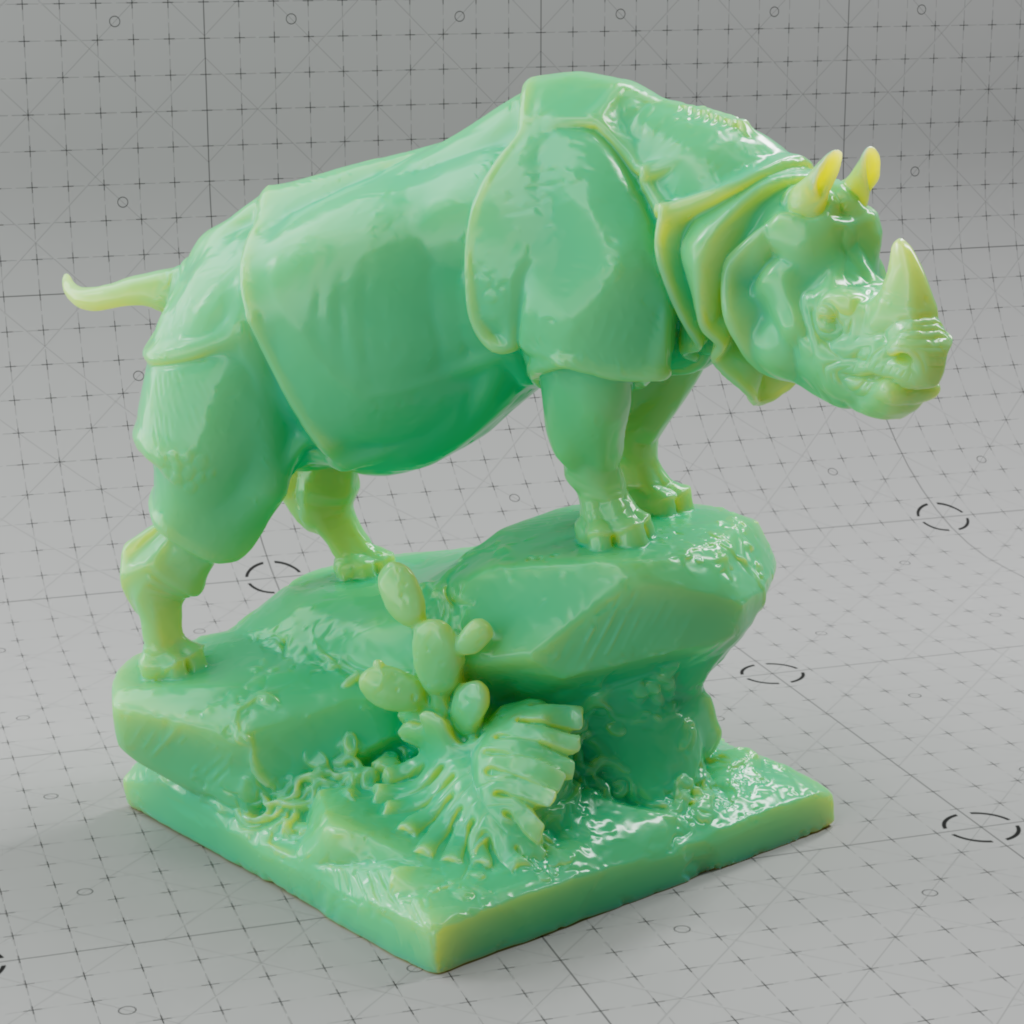
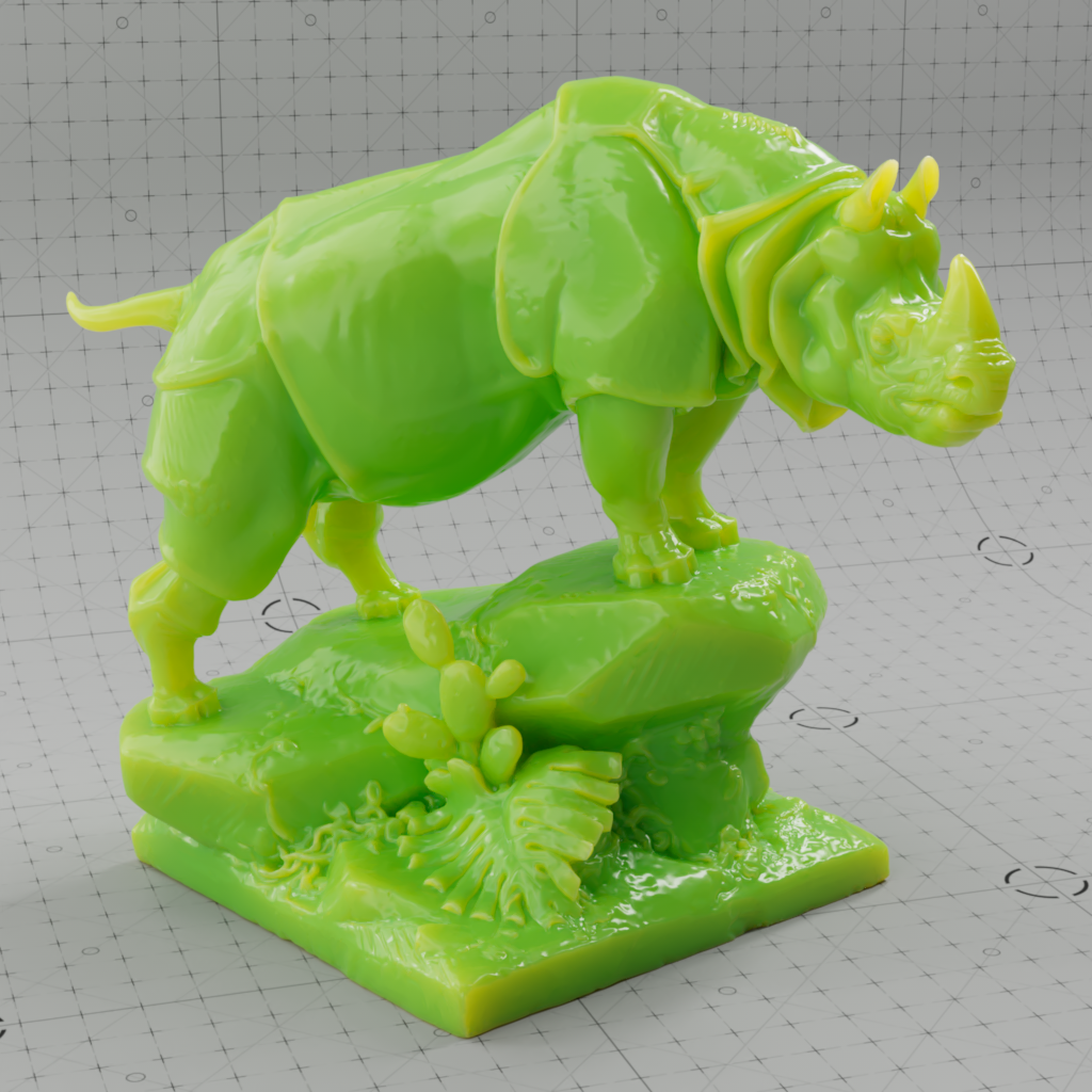
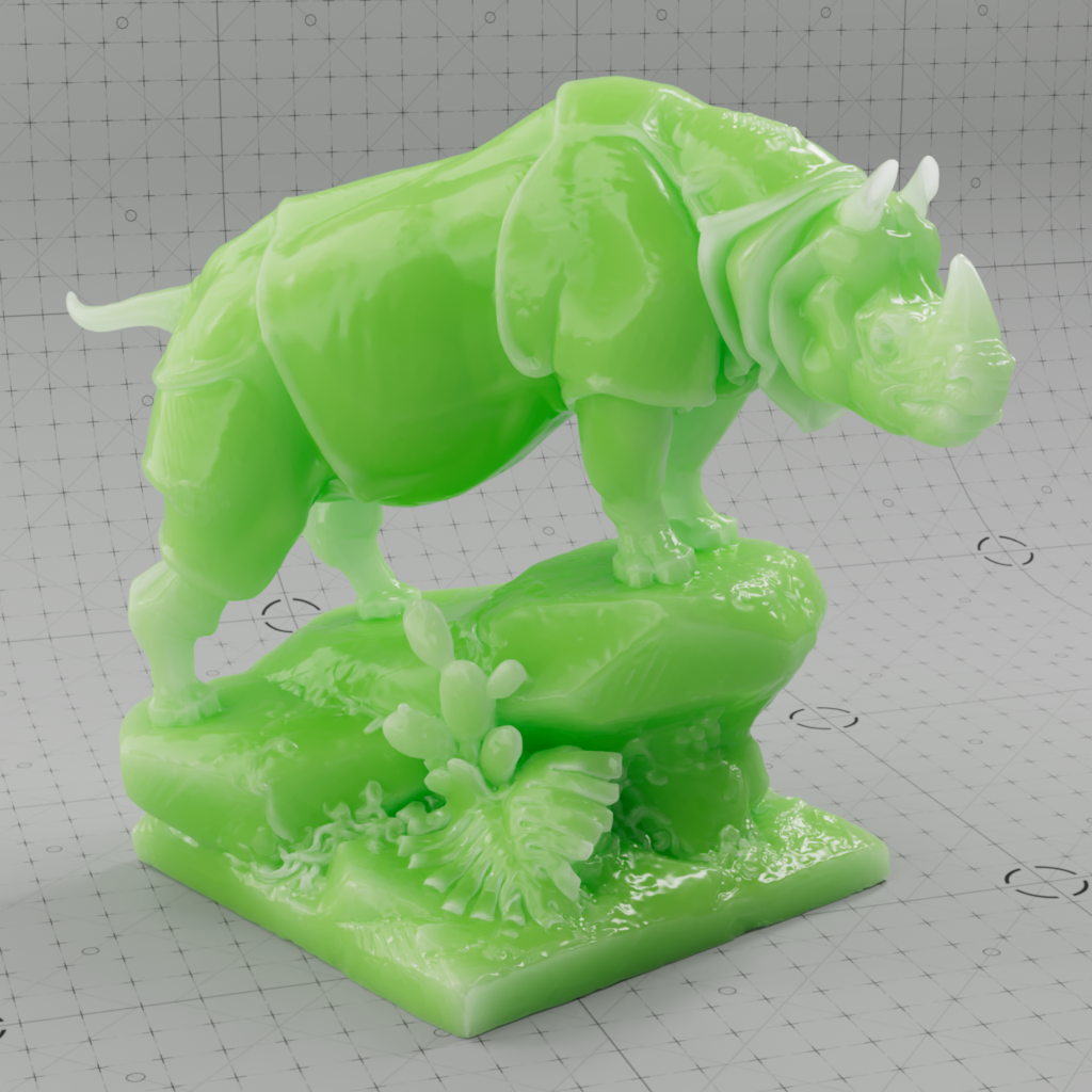
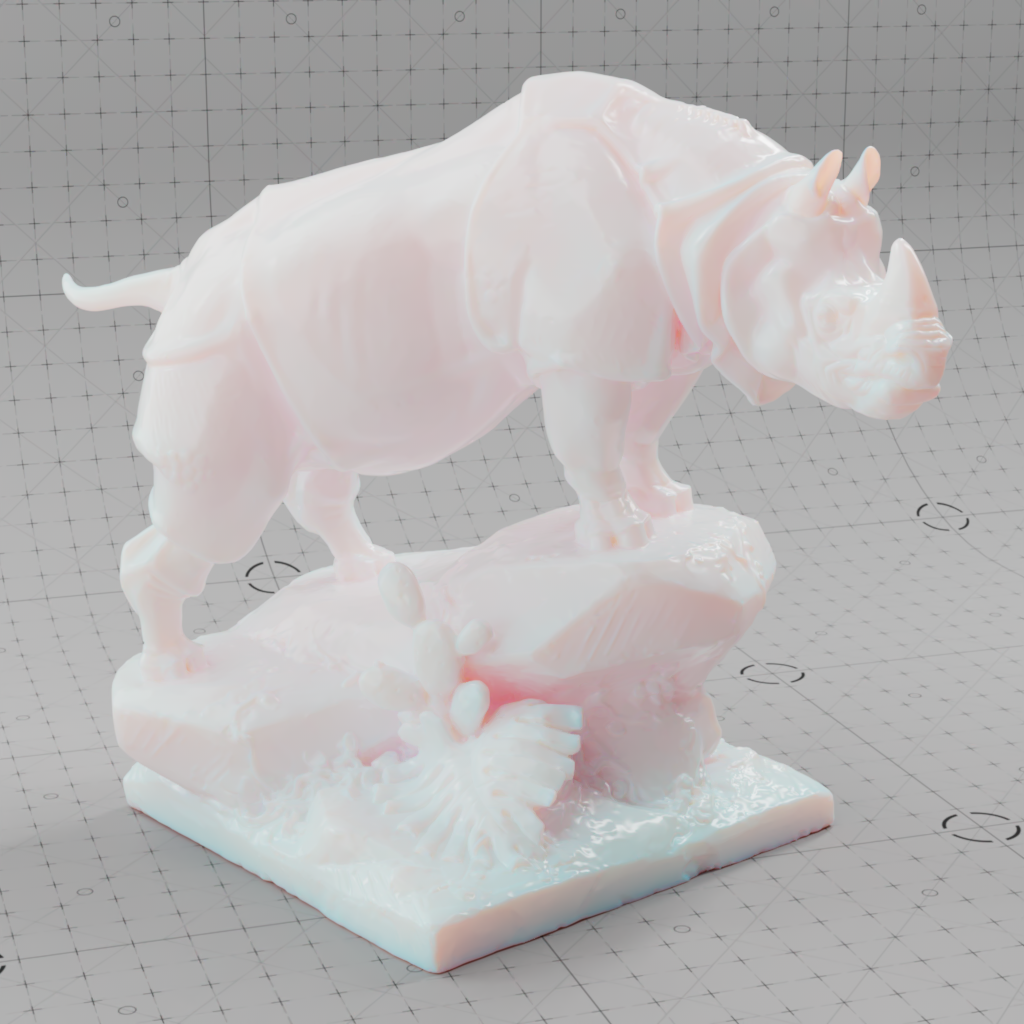
Subsurface Scattering (SSS) simulates light that penetrates the surface of an object and gets scattered around inside the geometry. Some of this light may exit the object again and illuminate the surface in that area. This effect is common for many real world materials, but best known for skin, wax candles, plastic, and even stones.
The general look of subsurface scattering is driven by three main components, the overall color (subsurface color), the color of the light that scatters inside the object and then returns to the surface (subsurface radius), and the total distance that the subsurface scattering effect can travel which makes things look more or less dense (subsurface scale). The subsurface scattering effect is very scale dependent so it's important to have an understanding of your scene's scale and the unit of measurement that you are working in.
For example, in human skin a skin tone would be appropriate for subsurface color, a generally reddish color for subsurface radius to emulate the blood vessels underneath the skin, and a relatively low scale so that the skin does not appear too thin.
The Subsurface parameters are also used to control a back-lighting/translucency effect when Thin Walled is enabled in the Geometry subsection.
If you encounter GI flickering due to SSS when using Irradiance Point Cloud, try increasing the Retrace Threshold to 3 or higher. This will use more Brute Force GI rays for the detailed parts of your scene and is likely to stop the flickering.
The example images for the Subsurface parameters below use the Random Walk subsurface mode unless noted otherwise.
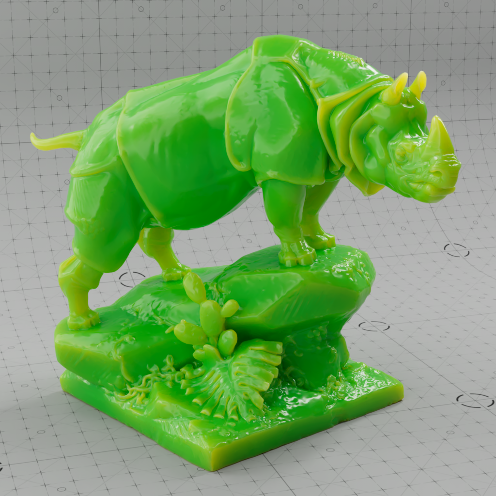
Credit to Three D Scans for the Rhinoceros model used in the example images below.
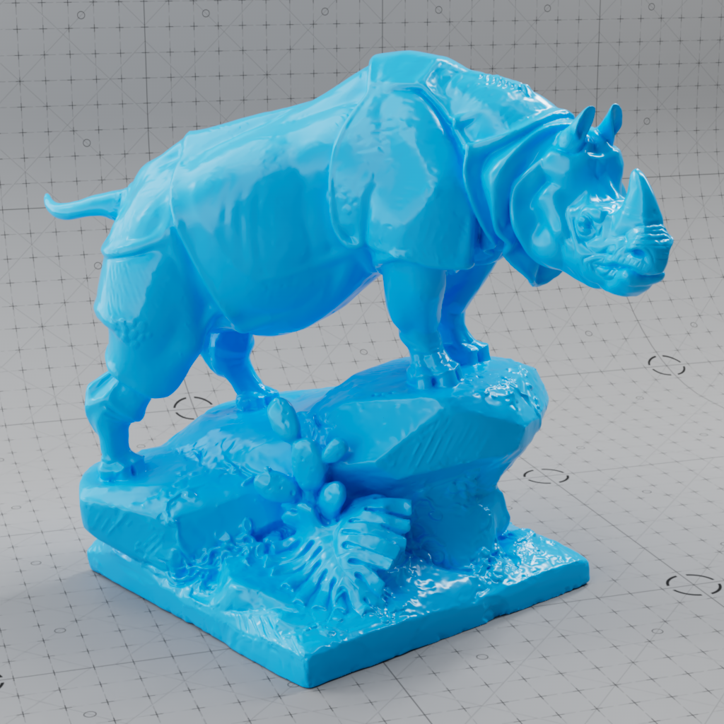
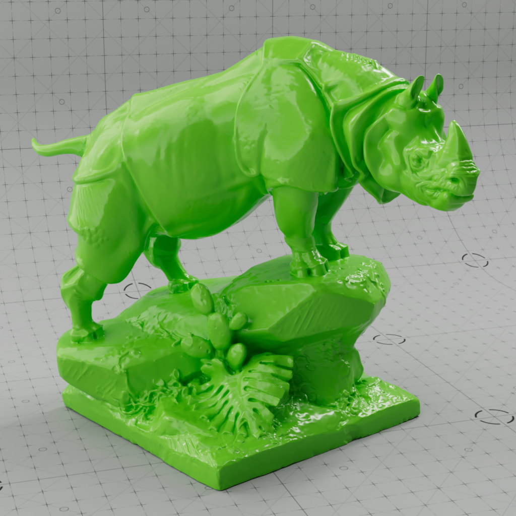
Light scattered inside the object takes on this overall color and transports it back to the surface.
In a material for human skin, a skin tone would be appropriate for the subsurface color.
Depending on the scale of the scattering this can be thought of similarly as an albedo color for subsurface scattering since low scattering values will result in a very diffuse look and where black is used no subsurface scattering will take place at all.

|
|
|

|
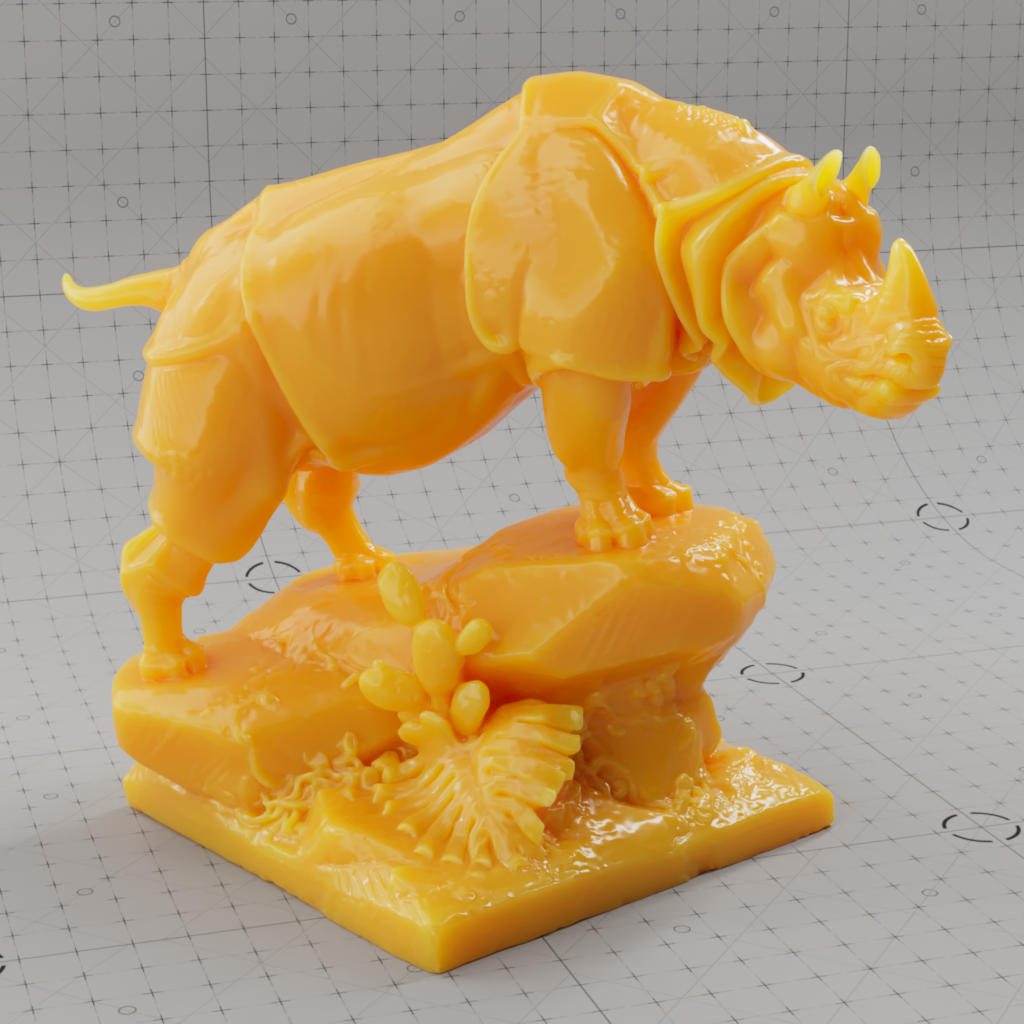
| Subsurface Color: White (default) Subsurface Radius: Orange (0.97, 0.62, 0.11) Subsurface Weight: 1 |
Green | Orange | Black |
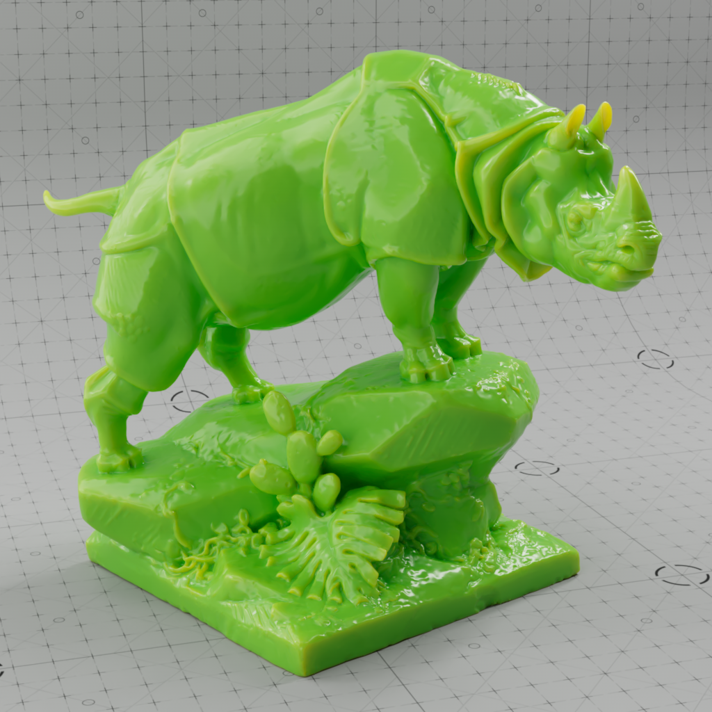
This can be used to blend between diffuse surface shading and subsurface scattering. With a Weight value of 1, diffuse shading has no effect and the full Subsurface Scattering effect becomes visible.
|
|
|
|
| Subsurface Weight: 0 | 0.5 | 0.75 | 1 |
Fixed Unit: Centimeters
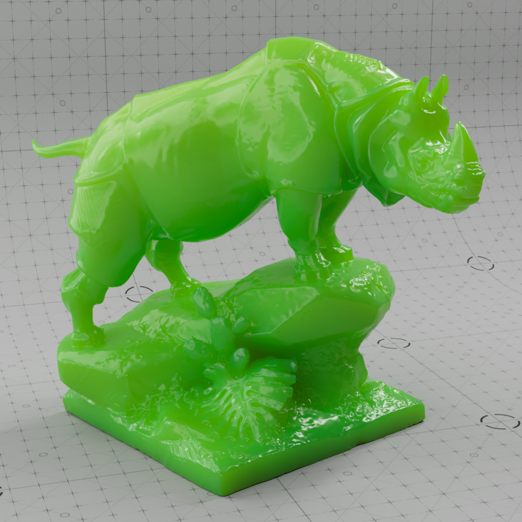
Subsurface radius controls the average distance the red, green, and blue wavelengths can travel and scatter before returning to the surface.
Lighter colors (higher values) result in more scattering and darker colors (lower values) result in less scattering. The default radius color white means all colors are scattered equidistant and a black radius color results in no subsurface scattering.
For example, a radius color with RGB values (1, 0, 0) means that only the red wavelength would travel beneath the surface and the green and blue components would be completely blocked from scattering.
The radius color is a very powerful parameter to tweak for many of the most interesting subsurface scattering looks.
Subsurface radius is in centimeters even though it is represented as a color input, however, it is recommended to use the subsurface scale parameter to control the overall distance subsurface light can travel.
Working this way makes it easier to author radius color maps rather than relying on high dynamic range color values above 1 in order to achieve the intended result because the total distance light can travel in a subsurface object is obtained by multiplying the subsurfaceRadius color values by the subsurfaceScale value.
For example, if red should scatter 7.5 scene units, green should scatter 5 scene units, and blue should scatter 1 scene unit then a radius color with RGB values (0.75, 0.5, 0.1) should be used in combination with a subsurface scale value of 10. The final result would be the same as using a radius color with RGB values (7.5, 5, 1) but with a subsurface scale of 1.
|

|

|
|
|
| Subsurface Radius: White (default) Subsurface Color: Light Green Subsurface Scale: 0.75 |
Light Blue (0, 0.5, 0.1) Light Green |
Red (1,0,0) Light Green |
Red (1,0,0) White |
Black (0,0,0) Light Green |
Subsurface scale controls the overall distance in scene units subsurface scattering can travel.
For example, if your scene is using centimeters then a value of 10 results in subsurface scattering traveling up to 10 centimeters.
The total distance light can travel in a subsurface object is obtained by multiplying the Radius color values by the Scale value.

|
|

|

|
| Subsurface Scale: 0 Subsurface Color: Light Green Subsurface Radius: Orange (0.97, 0.62, 0.11) |
0.25 | 1 (default) | 5 |
Only relevant for Random Walk mode. Values close to the extreme ends (-1 and 1) may result in an unwanted look as the light scattering becomes so highly concentrated in a single direction.
Anisotropy controls the direction light scatters inside a subsurface object within a -1 to 1 range. Adjusting a material's anisotropy allows for more artistic control and increased realism.
The default anisotropy of 0 results in isotropic scattering, when the light scatters equally in all directions. Positive values increase the chance for forward scattering, when more light is scattered in the direction the light rays are already traveling. Negative values increase the chance for back scattering, when more light is scattered back towards the location of the light source.
In the examples below, note how the final result is highly dependent on the location of the light source relative to the subsurface object. All examples showcase a subsurface anisotropy from -0.9 to +0.9, positive values frequently lead to a more glassy appearance while negative values lead to a more frosted look.
| Subsurface Anisotropy: -0.9 to +0.9 Front Lighting |
-0.9 to +0.9 Standard Lighting |
-0.9 to +0.9 Back Lighting |
The subsurface calculation offers the following methods:
|

|
|
| Subsurface Mode: Point-Based Diffusion | Ray-Traced Diffusion | Random Walk |
Point-Based Diffusion
If your scene is setup to use Point-Based Diffusion and you render in progressive mode it will automatically use Ray-Traced Diffusion during progressive renders. This way you can actually see the SSS effect in progressive mode (and not just the diffuse texture) and tweak settings interactively - while still using Point-Based Diffusionfor the final (bucket) rendering.
Please note that due to the differences in the two modes that the final result can differ when comparing progressive ray-traced SSS to the bucket rendered point-based SSS.
Ray-Traced Diffusion
Random Walk
Only relevant for Ray-Traced Diffusion and Random Walk subsurface scattering modes.
Controls the amount of noise or grain in the Subsurface calculation. Higher numbers will reduce potential grain issues but will take longer to render and vice-versa.
Only relevant for Ray-Traced Diffusion and Random Walk subsurface scattering modes.
Controls which objects are seen by the Scattering calculation.

|
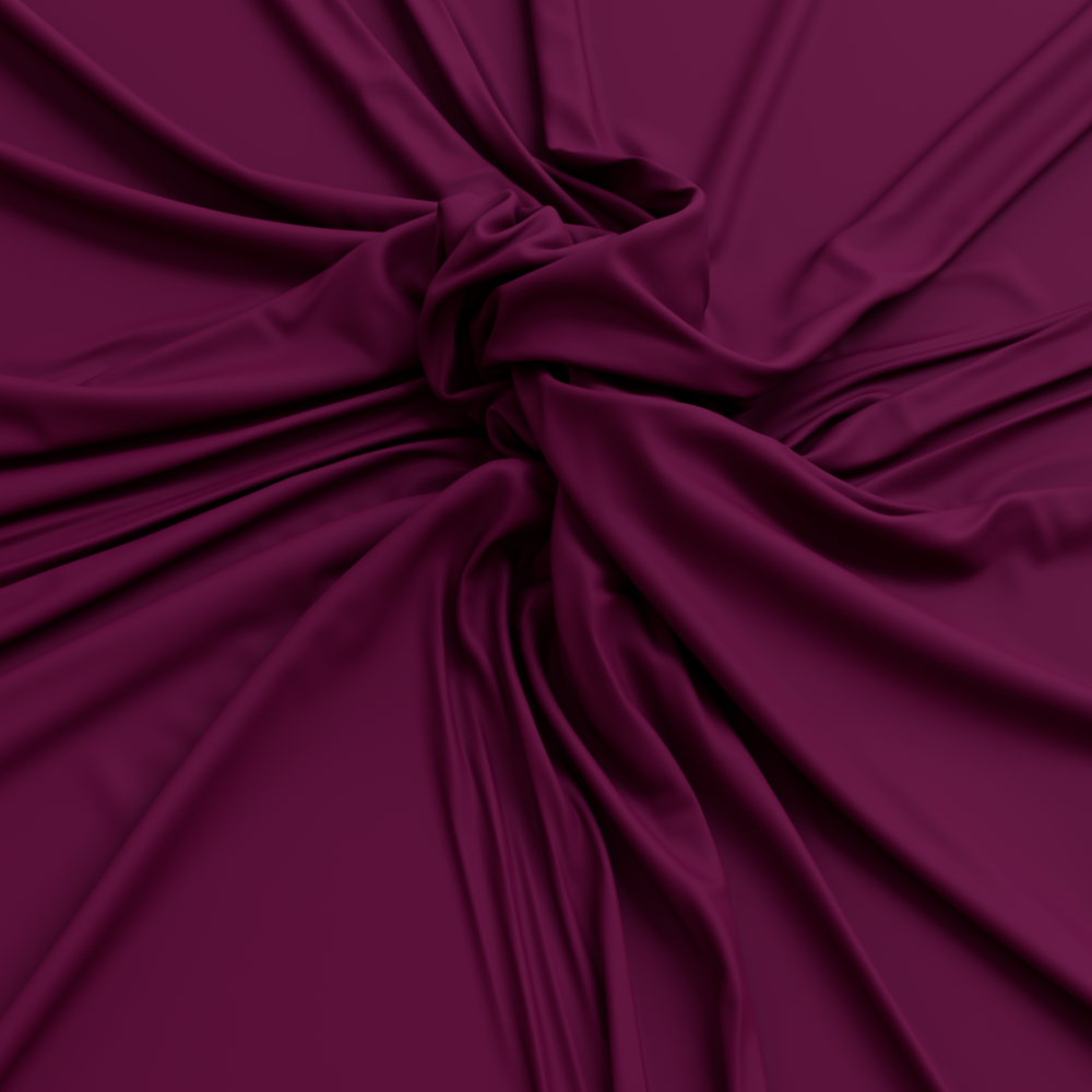
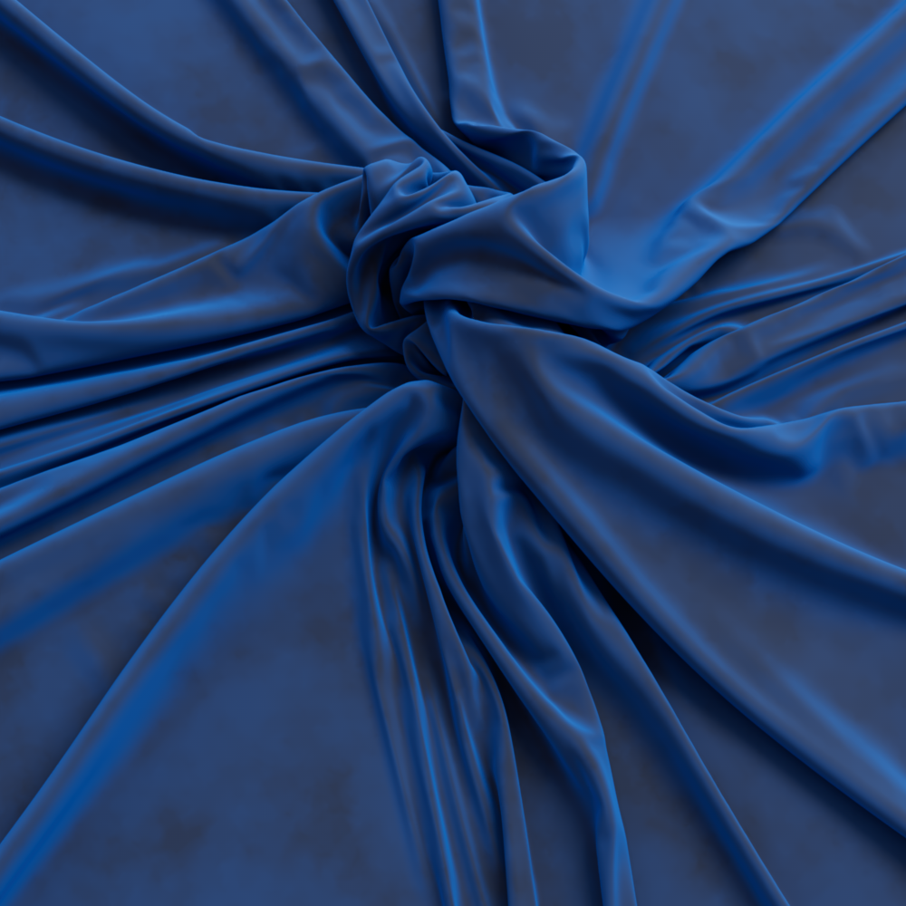
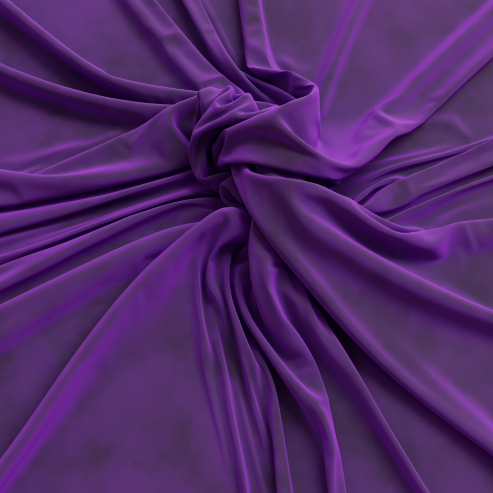
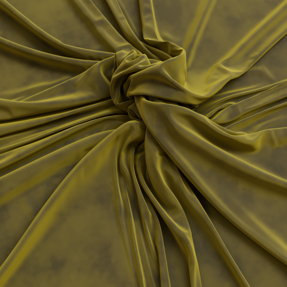
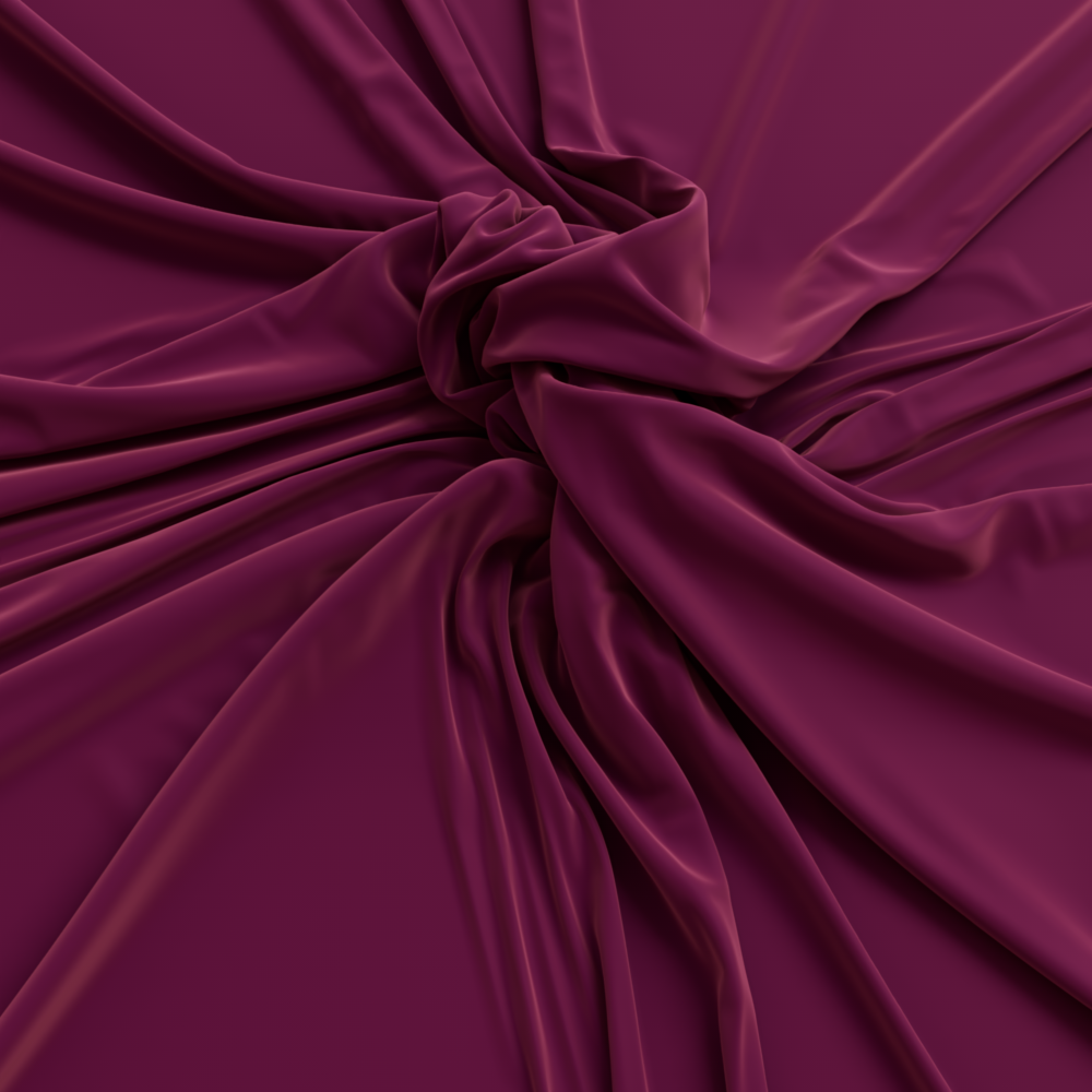
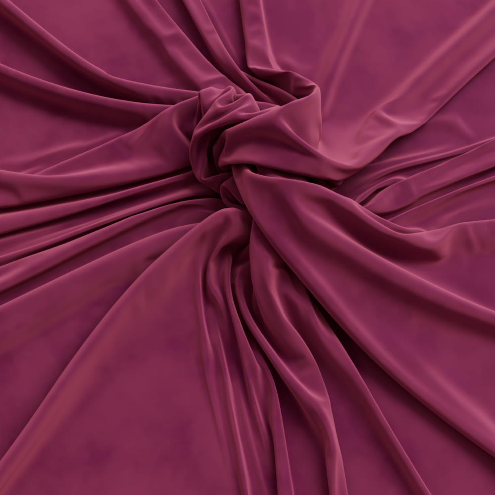
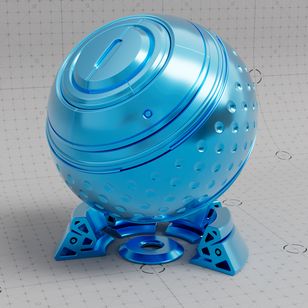
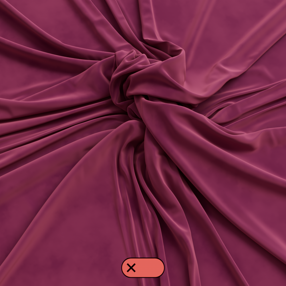
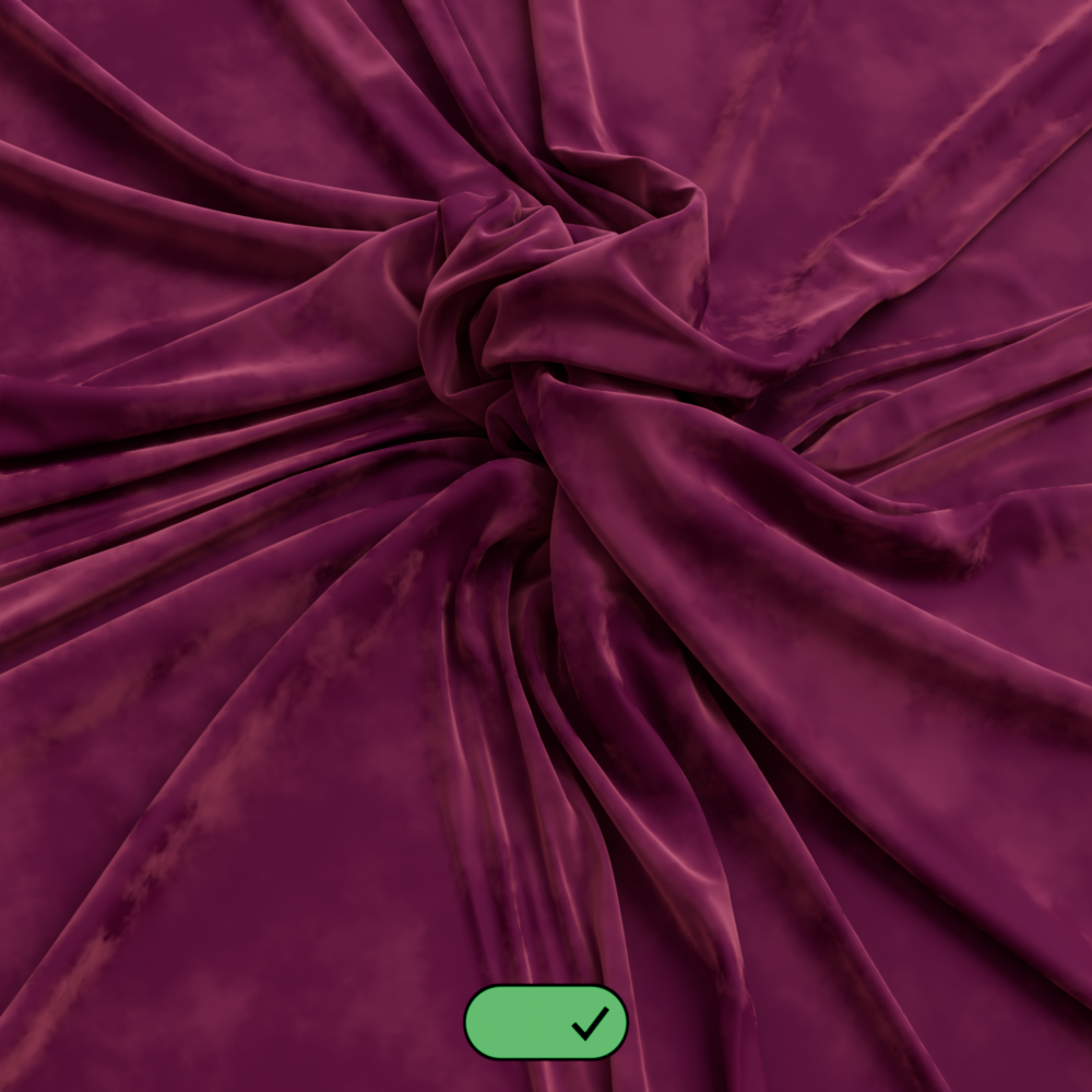
The Sheen effect can be used to simulate a soft backscatter effect commonly seen on fabrics like velvet or satin.

|
|
| Cloth with Sheen | Cloth without Sheen |
Controls the color tint of the sheen reflection.
Cloth model by Fuchs & Vogel
|
|
|

|
| Sheen Color: Blue | Purple | Yellow | Teal |
Controls the intensity of the sheen reflection. When 0.0 the sheen effect is disabled.
|
|

|
|
| Sheen Weight: 0.0 Sheen Color: Light Pink |
0.5 | 1.0 |
This controls the roughness of the sheen reflection, higher values result in a softer look.

|
|

|
|
| Sheen Roughness: 0.0 | 0.2 | 0.5 | Textured 0.3 - 1 |
A sheen with high a roughness value needs more samples to get a clean "noise-free" result. Higher sheen samples help reduce noise but will take longer to render and vice-versa.
|
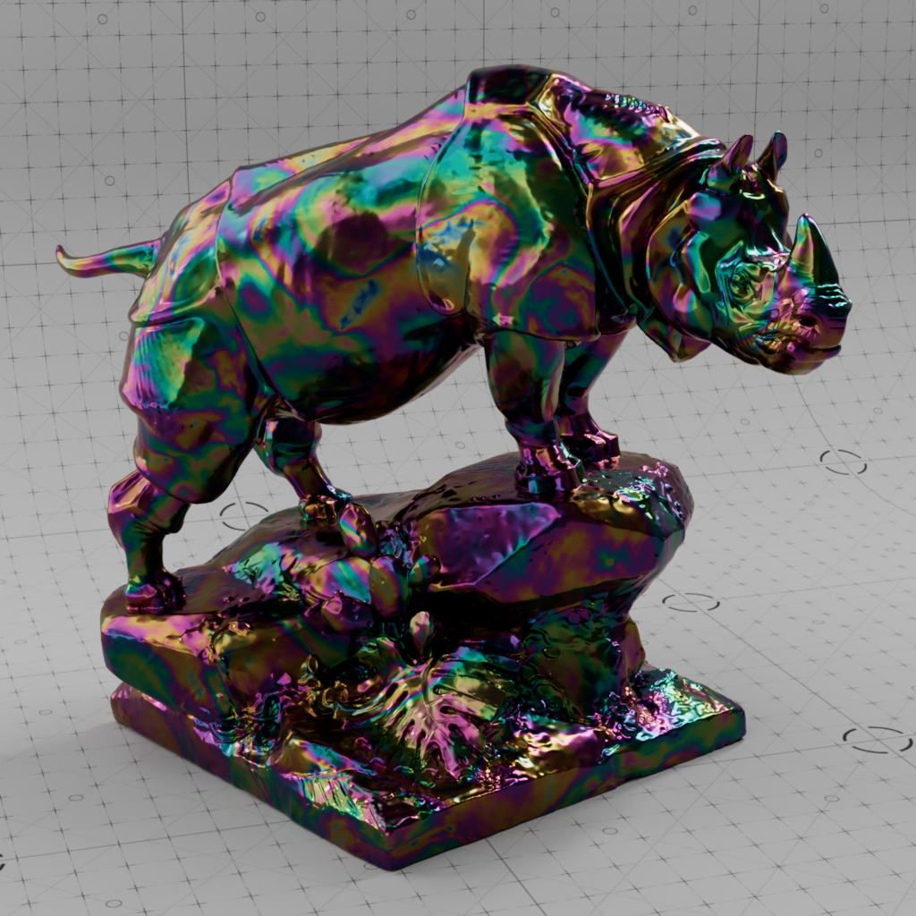
Thin Film can be used to simulate a thin, light-refracting layer on the surface. For example, the shimmer on an oil film or a soap bubble.
This is the refractive index of the thin layer on the surface. A thin film of water can be simulated with an IOR of 1.333. Since soap has an IOR of about 1.5, the thin film of a soap bubble could have an IOR of about 1.4 ((1.3+1.5)/2.0).
In the animated examples below note the massive effect thin film thickness has on color shift, both have an IOR range from 1 to 4 but the thickness is different.
| IOR: 1 to 4 Thickness: 50 |
1 to 4 300 |
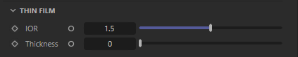
Fixed Unit: Nanometers
The thickness of this layer in nanometers and influences the color shift on this layer. This effect looks particularly interesting when thickness is varied slightly, for example, remapping a noise texture into an appropriate thickness range.
In the animated examples below note the massive effect thin film IOR has on color shift, both have a thickness range from 0 to 300 but the IOR is different.
|
||
| Thickness: 0 to 300 IOR: 2.0 |
0 to 300 3.0 |
Noise variation 100-500 2.0 |
|
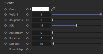
These options define an additional reflection layer over the material, this is helpful to emulate properties such as varnish, the clear coat of car paint, or slimy and wet surfaces. The coating layer also has its own bump map input which allows you to define details such as scratches separate from the base of the material, or leave as perfectly smooth.
Since the coating layer covers the entire material it will indirectly affect the strength of other material properties due to energy conservation, such as diffuse Base shading, Reflection, Transmission and Subsurface scattering.
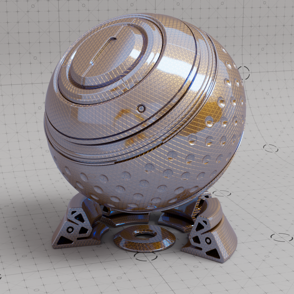
Controls the coat reflection color, using a different coat color compared to the primary reflection a two-tone effect can be achieved.
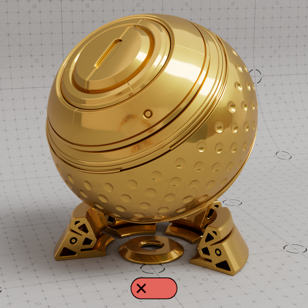
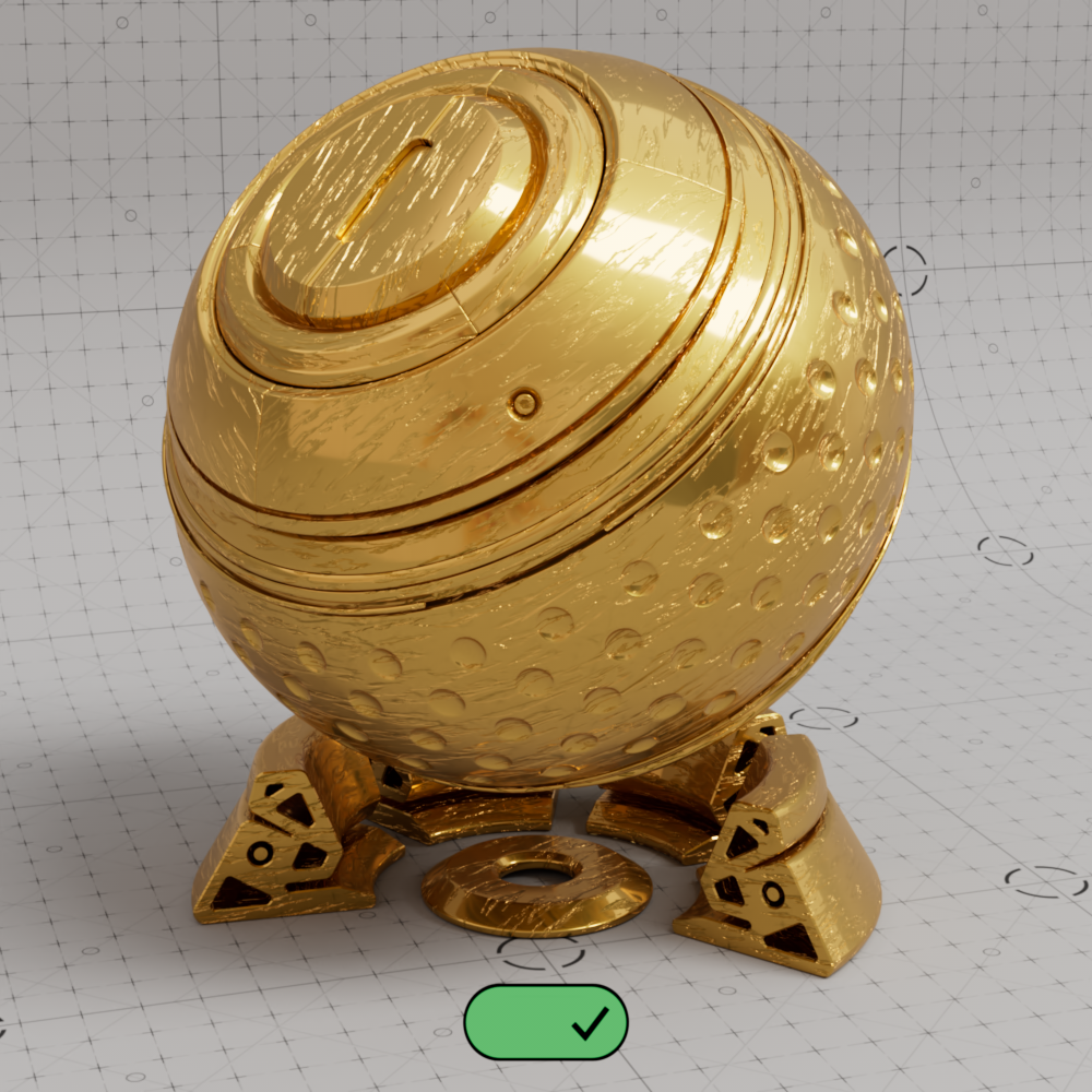
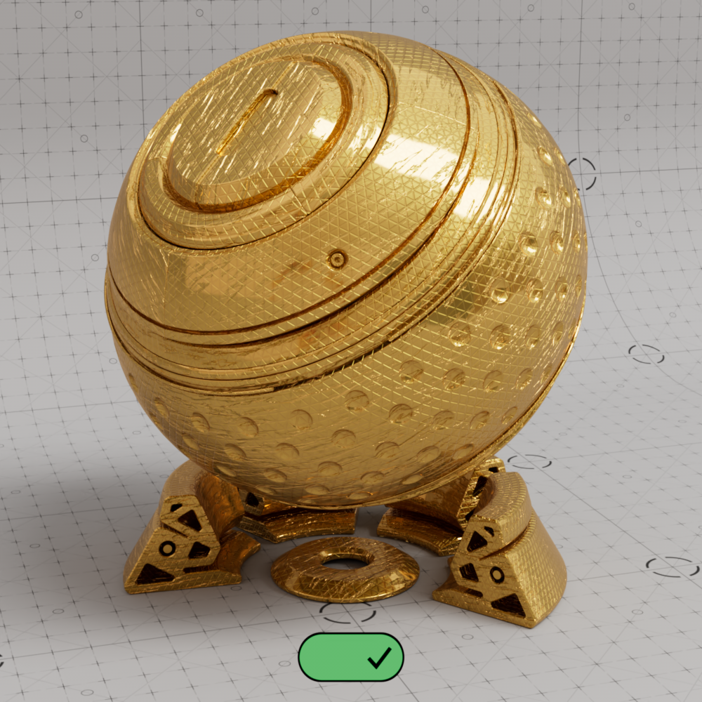
In the examples below a rough metallic shader with a triangular bump map pattern can be seen with a very shiny coating on top.

|

|

|
|
| Coat Color: White (default) | Yellow | Red | Blue |
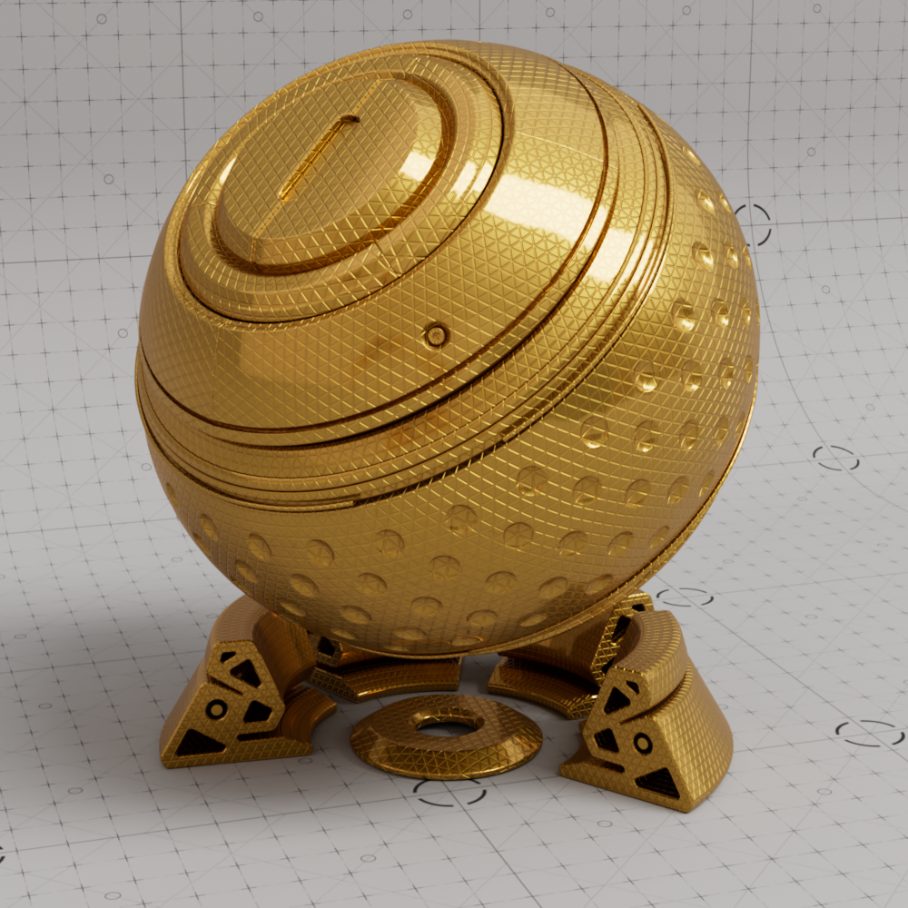
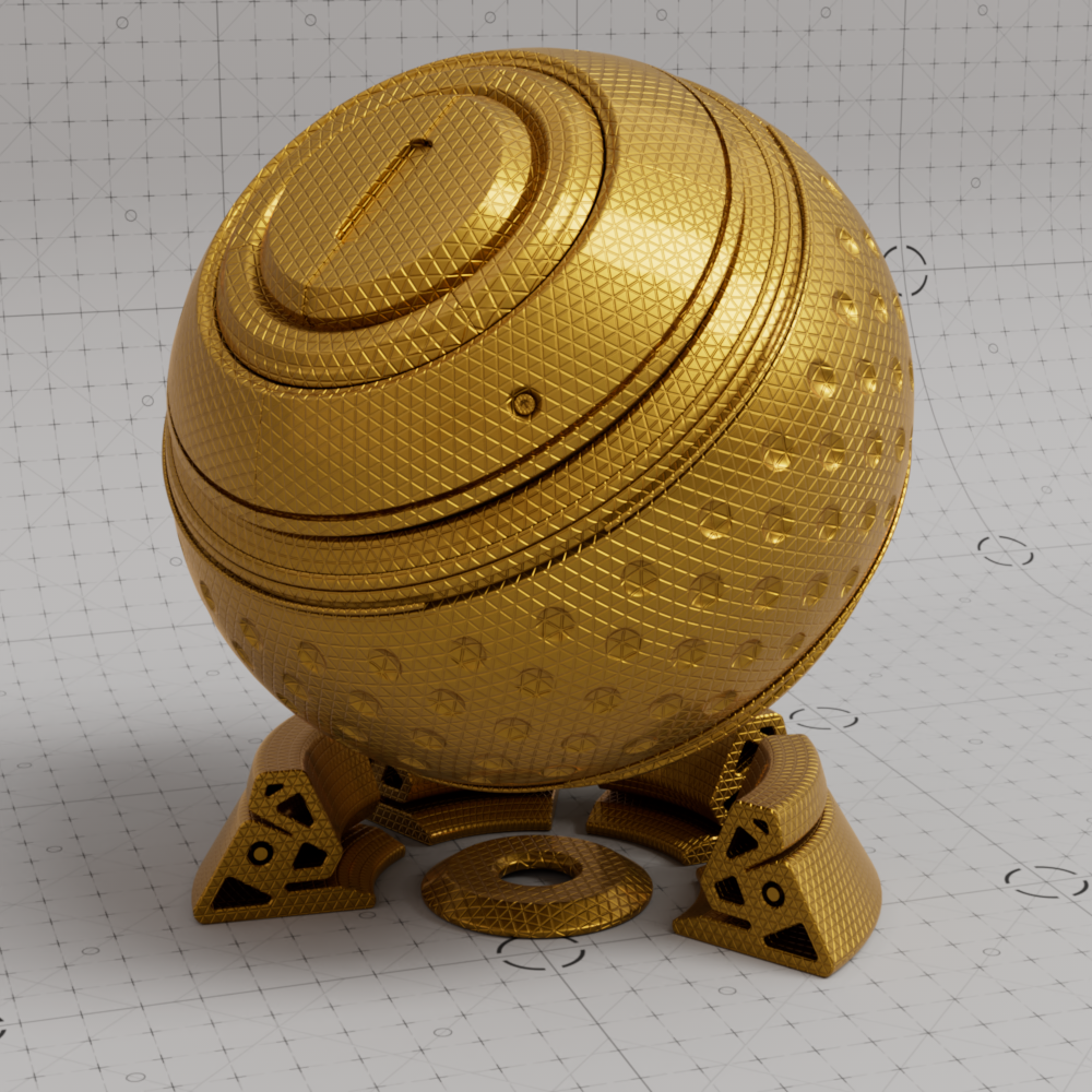
Controls the intensity of the coating reflection. Coat is disabled at 0.0.

|
|

|
| Coat Weight: 0 | 0.5 | 1 |
This is the roughness of the surface reflection. A roughness value of 0.0 means perfectly 'polished', or full glossiness. A roughness value of 1.0 means almost diffuse appearance.
| Coat Roughness: 0 to 1 |
The index of refraction used to calculate the strength of the coatings fresnel effect. An IOR of 1.0 disables the coat.
Note that the clearly defined coating specular highlight compared to the rough base metal reflection.

|
|
|
|
| Coat IOR : 1 | 1.5 | 2 | 3 |
This allows to you stretch coat reflections in a direction based on the anisotropy rotation. Anisotropy is used to emulate materials such as brushed metals where surface roughness is focused in a particular direction. Reflection Roughness must be set above 0.0 to see the effect.
|
|

|
| Coat Anisotropy: 0 | 0.5 | 1 |
Rotates the direction of the anisotropic reflections. Input values range 0 to 1 which is equal to the rotation angles 0° to 360°.
| Coat Aniso Rotation: 0 to 1 |
Blurry reflections (when Roughness is greater than 0.0) will need multiple samples to get a clean "grain-free" result. Higher numbers will reduce any potential grain issues, but will take longer to render and vice-versa.
Connect a bump map node to this input to that will only affect coating reflections. Coat bump mapping is separate from the base layer, this means you can apply details like scratches on the coating without affecting the base layer.
Alternatively, by plugging a bump map into the base 'Geometry' Bump input of the material and leaving the 'Coating' Bump input empty you can easily achieve a clear coat or varnish effect:
|
|

|
|
| Coat Bump: Disabled Base Bump: Disabled |
Enabled Disabled |
Disabled Enabled |
Enabled Enabled |
|
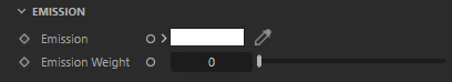
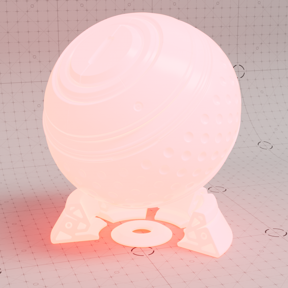
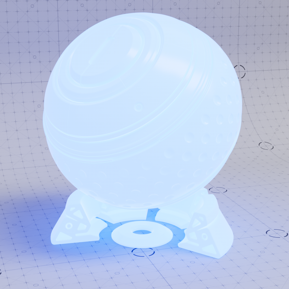
Emission can be used for surface illumination effects, and when rendered with Global Illumination will emit light into the scene when the effect is strong enough based on the emission weight.
Controls the color of the emission. Emission simulates light in the scene by using indirect global illumination rays to cast diffuse lighting on other objects in the scene. The emission color blends with the underlying properties of the material, however when emission weight is high enough it will completely overpower the rest of the material.
|
|

|

|
|
| Emission Color: Red Emission Weight: 10 |
Blue | Yellow | Grey | Black |
Controls the intensity of the emission in radiance units, higher values result in brighter colors and stronger global illumination.
| Emission Radiance: 0 to 25 Emission Color: Red |
|
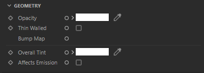
Geometry settings affect the overall shading and calculation of the surface. For example, here you will find the option to assign a bump map, control the overall opacity of the material or tint the entire material with a color or texture.
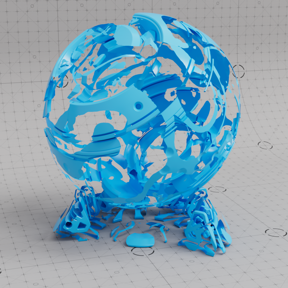
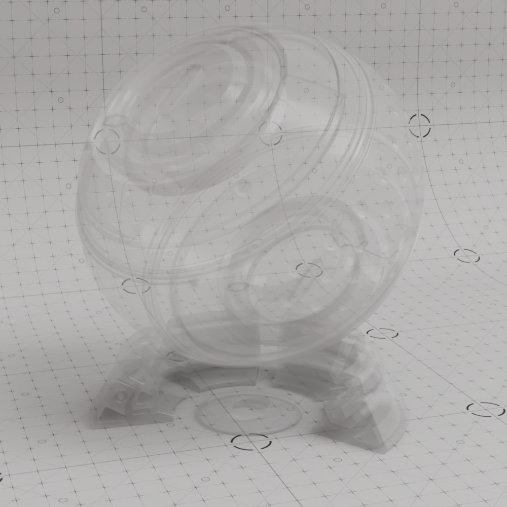
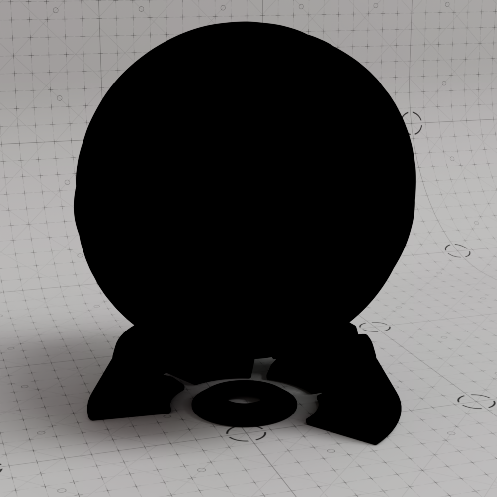
This color controls the overall opacity of the material, with colors closer to white being more opaque. An opacity of black means the material will be fully transparent.
This effect is entirely dependent on the Transparency trace depth found in the Render Settings Globals section. If you only need cutout transparency you should instead make use of the drastically more efficient Redshift Sprite shader.
Grey-scale values are typically used to describe opacity but other colors can be used with varying effects, the resulting refraction color is the inverse of opacity color.

|

|

|
|
|
| Opacity Color: White Base Material: Blue |
Grey | Black | Green | Textured |

|
|
|

|
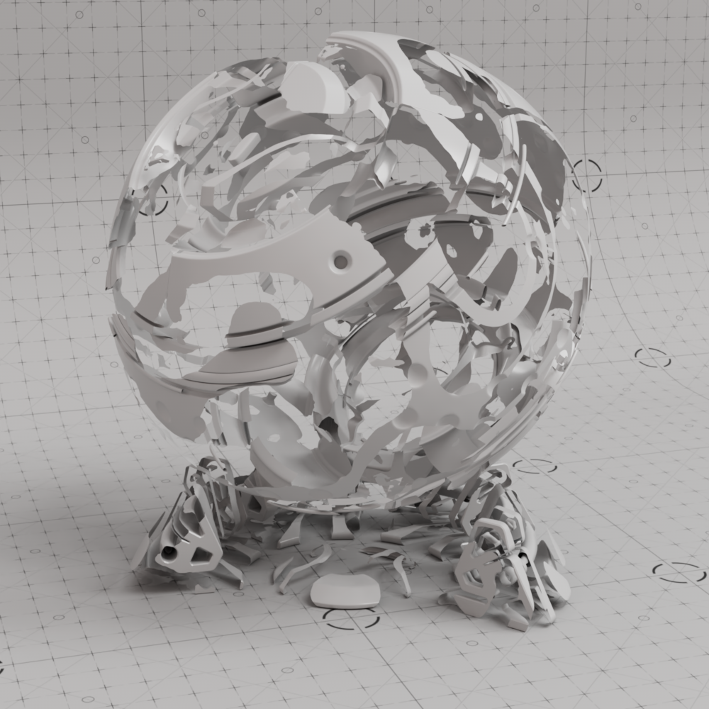
|
| Opacity Color: White Base Material: Grey |
Grey | Black | Green | Textured |
This option is useful for thin refractive materials such as a pane of glass, where the ray-bending effect is not noticeable and modeling actual object thickness is not worth it. When this option is enabled, refraction rays will enter and immediately exit the medium without bending the rays.
When Thin Walled is enabled the behavior of the Standard Material changes in the following key ways:
The Subsurface parameters are used to control a back-lighting/translucency effect.
Dispersion effects are disabled.
The Thin Walled option is available for rendering thin transparent objects that don't actually have modeled thickness, such as a pane of glass. For very thin objects, refractive rays will not travel enough of a distance inside the object before exiting to show any noticeable bending effect. Enabling this option preserves the reflection Fresnel effect while internally disabling any medium interface transition math that would allow rays to bend.
In the examples below you can see a noticeable difference when this option is enabled. When enabled by default, the refractions bend and distort realistically - however, when disabled no bending occurs and instead the background can be seen straight through to the other side.

|
|
| Thin Walled: disabled |
Thin Walled: enabled |
Connect your overall bump map here.
This is an overall tint for the entire material.
The Overall Tint parameter allows you to tint the entire material after lighting has been calculated. This parameter is also useful if you want to apply additional lighting attenuation from effects such as ambient occlusion, to accentuate shadows around crevices.
Below shows examples of Overall Tint. See how it affects both diffuse lighting and reflections:

|

|
|
|

|

|
| Overall Tint: White | Grey | Black | Pink | Green and blue texture | AO shader |
When enabled the Overall Tint color affects the emission color. When using the Overall Tint for certain shading effects, like ambient occlusion, you should leave this option disabled for more realistic results.
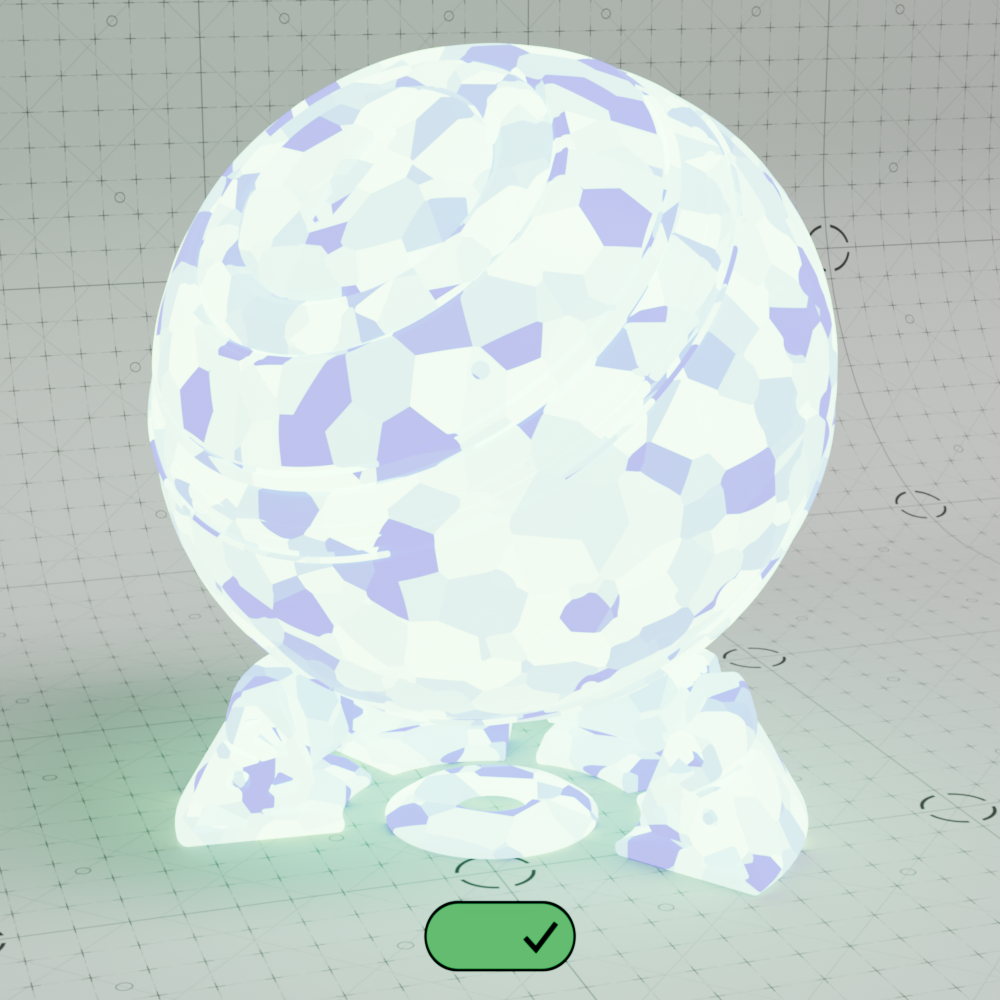
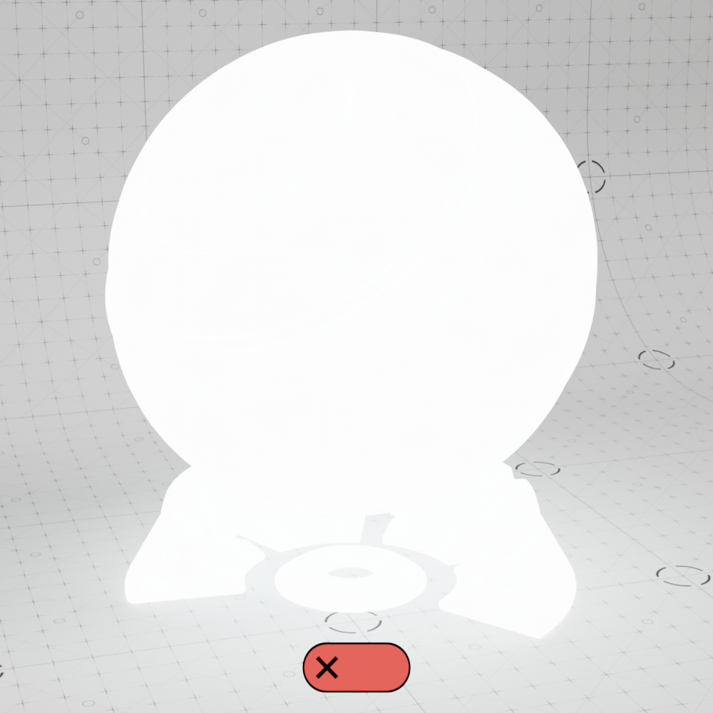
In the examples below an AO shader or a texture is used to drive the Overall Tint of the emissive shader ball. When the option is enabled the AO shadow or voronoi texture affects the emissive color and strength of the ball material:
|

|
|
| Overall Tint Affects Emission: Enabled | Disabled | (Reference) Overall Tint without Emission |
|
|
|

|
Optimization settings allow you to fine-tune shading effects that can have a significant impact on the render performance of the material.
This enables the per-material Reflection and Refraction Trace Depth parameters below. When disabled, the global trace depths will be used.
This parameter controls the trace depth for reflection rays shot from this material. If the reflection rays of a material are not very defined (meaning: they are blurry because of the roughness parameter or have a low weight), then multiple bounces can be a waste of rendering time. This parameter allows the user to reduce the trace depth and speed up rendering.
This parameter allows you to override the global cut-off setting for reflections.
When the reflections of a material are very dark (because of low "Weight" or "Color" values) they contribute very little to the final image. This parameter defines what is considered "very dark" at which point no more reflection rays will be shot - which will speed up rendering. Scenes containing very strong lights might need this parameter set to very low values such as 0.0001 in order to avoid early termination of tracing which can produce a grain-like effect.
This parameter controls the trace depth for transmissive refraction rays shot from this material. If the refraction rays of a material are not very defined (meaning: they are blurry because of the roughness parameter or have a low weight), then multiple bounces can be a waste of rendering time. This parameter allows the user to reduce the trace depth and speed up rendering.
This parameter allows you to override the global cut-off setting for transmissive refractions.
When the refractions of a material are very dark (because of low "Weight" or "Color" values) they contribute very little to the final image. This parameter defines what is considered "very dark" at which point no more reflection rays will be shot - which will speed up rendering. Scenes containing very strong lights might need this parameter set to very low values such as 0.0001 in order to avoid early termination of tracing which can produce a grain-like effect.
This controls the combined trace depth for your Redshift material shader.
"Use Combined Trace Depth from Materials" must be enabled in the 'Render Settings' System > Legacy.
When the Enable Trace Depth Override' option is enabled, the material trace depths defined here are used instead of the global ones. This can be useful for fine-tuning performance on a per material basis where dropped bounces might not be noticed.
When the 'Reflection' and 'Refraction' Cut-off Overrides are enabled, the cut-off values are used instead of the global ones.
|
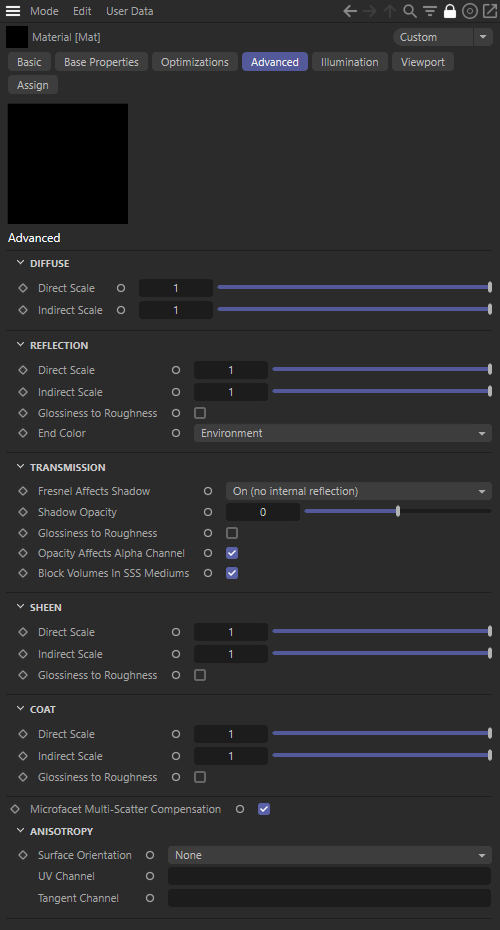
The advanced options allow you to tune powerful features of the material that may not be frequently used and may break realism and energy conservation.
This parameter allows you to independently scale the weight of direct diffuse lighting rays, i.e. rays that intersect lights in the scene. Setting this value to 0.0 disables direct lighting for the diffuse component.
For physically correct results both the 'Direct' and 'Indirect' lighting scales should be 1.0 (or the same value).
In the example animation note how the white diffuse shading from light objects diminishes with low direct scale values while indirect lighting off of other objects, like the blue background, is still visible bouncing onto the underside of the shader ball. Also note the white bounce lighting from the shader ball back onto itself is still visible in the crevices with low direct scale.
| Diffuse Direct Scale: 0 to 1 |
This parameter allows you to independently scale the weight of indirect diffuse lighting rays, i.e. rays that intersect surfaces in the scene. Setting this value to 0.0 disables indirect lighting (global illumination) for the diffuse component, which may be a useful optimization when indirect lighting is already extremely subtle.
In the example animation below note how the blue bounce lighting on the underside of the shader ball diminishes with low indirect scale values while the white direct lighting from lights does not change. Also note the crevices on the shader ball become darker with low indirect scales because it is no longer bouncing white light back onto itself.
| Diffuse Indirect Scale: 0 to 1 |
This parameter allows you to independently scale the weight of direct reflection rays, i.e. rays that intersect lights in the scene. Setting this value to 0.0 effectively disables direct lighting (specular reflections of lights) for reflections.
Note for physically correct results both the 'Direct' and 'Indirect' lighting scales should be 1.0 (or the same value).
In the example animation below note how the white reflections from lights in the scene diminish with low direct scale values while indirect reflections of other objects, like the blue background, are still visible. Also note the self reflections of the shader ball are still visible even with a low direct scale.
| Reflection Direct Scale: 0 to 1 |
This parameter allows you to independently scale the weight of indirect reflection rays, i.e. rays that intersect surfaces in the scene. Setting this value to 0.0 effectively disables indirect lighting (reflections of other objects) for reflections, which can be a useful optimization and is equivalent to the 'Specular Highlights Only' option that can be found in some older Redshift materials.
In the example animation below note how the blue reflections from the background diminish with low direct scale values while the white reflections from lights in the scene remain visible. Also note the self reflections of the shader ball disappear with a low direct scale.
| Reflection Indirect Scale: 0 to 1 |
When enabled this option inverts a glossiness input to the equivalent roughness value. This option is useful when you have legacy textures that use the glossiness convention - i.e. where a glossiness value of 0.0 is maximum roughness and a value of 1.0 is perfectly smooth, the exact opposite of the roughness convention.
By default a transmission roughness of 0 inherits the same roughness as the reflections, because of this the convert from glossiness to roughness parameter also affects transmission roughness.

|
|
| Convert Gloss to Rough: Disabled Reflection Roughness: |
Enabled |
This setting controls what is reflected when the Reflection Trace Depth is exceeded.
When trace depths are low or an object's shape creates many self reflections this parameter can have an enormous difference on the final look. For example, the metallic shader ball in the examples below appears to glow in confined spaces when the reflection trace depth is low and End Color is set to "Environment." This is because the dome light environment is a nice bright sky reflection, once the final trace depth is reached these confined areas then reflect the bright sky even though they are primarily occluded by geometry.
Increasing the reflection trace depths can fix this issue, resulting in more realistic dark reflections, but this comes at the expense of render times - alternatively the End Color can be set to "Diffuse." Sometimes this is enough to produce a very similar darkened result to increasing the trace depths but avoids increased render times.

|
|
| End Color: Environment Reflection Trace Depth: 4 |
Environment 32 |
|

|
| End Color: Diffuse Reflection Trace Depth: 4 |
Diffuse 32 |
Only relevant when Thin Walled is disabled.
Controls whether reflectance is taken into account when calculating a transmissive object's shadow from the following options:
On: Fresnel reflectance is taken into account which results in more physically accurate shadow rendering, sometimes resulting in a sort of pseudo-caustic result. For most circumstances, where the heavy performance cost of caustic rendering is too great, Fresnel Affects Shadow will result in much more realistic renders in a fraction of the time. Even completely clear materials like glass cast a shadow and under certain circumstances they can be quite dark, this is because light reflected off the object may be more concentrated in some directions than others.
On (no internal reflection) - Default: Fresnel reflectance is taken into account but internal reflections are ignored resulting in a weaker shadow overall. This setting results in more realistic shadows than the off setting without shadows that could be too dark for something like a thick pieces of glass as seen in the example images below.
Off: Fresnel reflectance is not taken into account and the shadow of a transmissive object is controlled entirely by the Shadow Opacity parameter.
Please keep in mind that the softness of the shadow is entirely dependent on the lights in the scene.
|
|
|
|
| Fresnel Affects Shadow: On Shadow Opacity: 0 |
On (no internal reflection) 0 |
Off 0 |
In the example images below note how the shadows of the objects are brighter in the center than their edges because the fresnel reflections from the curved surface is scattering light away. Still, for the most realistic transmissive shadows Shadow Opacity should be set to 1 (resulting in a completely opaque shadow) and caustics should be used to more accurately light up the shadowed area as seen in the caustic rendering reference image below.
|
|
|
|
| Fresnel Affects Shadow: On Shadow Opacity: 0 |
Caustic Rendering Reference Shadow Opacity: 1 |
Fresnel Affects Shadow: Off Shadow Opacity: 0 |
The effect reflections have on shadow transparency can be seen in the images below, note how the shadow becomes darker as the reflection weight is increased.
|
|
|
|
| Reflection Weight: 0 Fresnel Affects Shadow: On |
0.5 | 1 |
Shadow Opacity controls the strength of transmissive shadows ranging from a value of -1 to 1, the behavior of this parameter is dependent on the Fresnel Affects Shadow option.
When rendering a transmissive object with caustics a Shadow Opacity of 1 is recommended, resulting in a completely opaque shadow, so the caustic effect can then brighten up the shadow more realistically.
When 'Fresnel Affects Shadow' is set to on or on (no internal reflection):
A value of 0.0 means the shadow is fully transparent except where reflectance has an effect on shadow transparency.
Negative values result in transmissive shadows that become more transparent until -1 when shadows are no longer visible.
Positive values result in more opaque shadows until 1 when a shadow becomes completely opaque.
|
|
|
|
|
|
| Shadow Opacity: -1 Fresnel Affects Shadow: On |
-0.3 |
0 | 0.3 | 1 |
When 'Fresnel Affects Shadow' is off:
A value of 0.0 means the shadow is fully transparent, negative values have no effect.
Positive values result in more opaque shadows until 1 when a shadow becomes completely opaque.
|
|
|
|
| Shadow Opacity: 0 Fresnel Affects Shadow: Disabled |
0.3 | 1 |
When enabled this option inverts a glossiness input to the equivalent roughness value. This option is useful when you have legacy textures that use the glossiness convention - i.e. where a glossiness value of 0.0 is maximum roughness and a value of 1.0 is perfectly smooth, the exact opposite of the roughness convention.
By default with this option enabled, refraction and opacity will affect the alpha channel. So if your object has 50% transparency your alpha channel will reflect that with 50% alpha. When disabled, the object will always have a solid alpha channel unaffected by transmission.
When enabled, volumetric objects are not rendered where they lie within a Subsurface Scattering volume.
When disabled, by default, lights are sampled using multiple importance sampling (MIS) for refractions. When brute force caustics are used this option is forced off.
When enabled, indirect light rays are sampled for refractions without multiple importance sampling — this matches the look of scenes made before the addition of MIS for refractions. When thin-walled is enabled, this option is forced on.
This parameter allows you to independently scale the weight of direct sheen reflection lighting rays, i.e. rays that intersect lights in the scene. Setting this value to 0.0 effectively disables direct lighting for the sheen component.
Note for physically correct results both the 'Direct' and 'Indirect' lighting scales should be 1.0 (or the same value).
In the example animation below note how the white sheen reflections from lights in the scene diminish with low direct scale values while indirect reflections of other objects, like the blue background, remain visible.
| Sheen Direct Scale: 0 to 1 |
This parameter allows you to independently scale the weight of indirect sheen reflection lighting rays, i.e. rays that intersect surfaces in the scene. Setting this value to 0.0 effectively disables indirect lighting for the sheen component, which can be a useful optimization.
In the example animation below note how the blue sheen reflections from the background diminish with low direct scale values while the white reflections from lights in the scene remain visible. Also note the self reflections of the shader ball disappear with a low direct scale.
| Sheen Indirect Scale: 0 to 1 |
When enabled this option inverts a glossiness input to the equivalent roughness value. This option is useful when you have legacy textures that use the glossiness convention - i.e. where a glossiness value of 0.0 is maximum roughness and a value of 1.0 is perfectly smooth, the exact opposite of the roughness convention.
|
|
| Convert Gloss to Rough: Disabled | Enabled |
This parameter allows you to independently scale the weight of direct reflection rays for coat reflections, i.e. rays that intersect lights in the scene. Setting this value to 0.0 effectively disables direct lighting (specular reflections of lights) for coat reflections.
Note for physically correct results both the 'Direct' and 'Indirect' lighting scales should be 1.0 (or the same value).
| Coat Direct Scale: 0 to 1 |
This parameter allows you to independently scale the weight of indirect reflection rays for coat reflections, i.e. rays that intersect surfaces in the scene. Setting this value to 0.0 effectively disables indirect lighting (reflections of other objects) for coat reflections, which can be a useful optimization.
| Coat Indirect Scale: 0 to 1 |
When enabled this option inverts a glossiness input to the equivalent roughness value. This option is useful when you have legacy textures that use the glossiness convention - i.e. where a glossiness value of 0.0 is maximum roughness and a value of 1.0 is perfectly smooth, the exact opposite of the roughness convention.

|

|
| Convert Gloss to Rough: Disabled | Enabled |
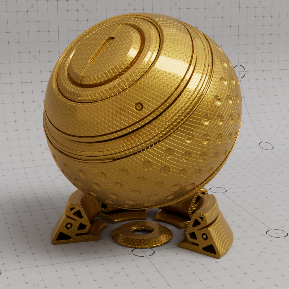
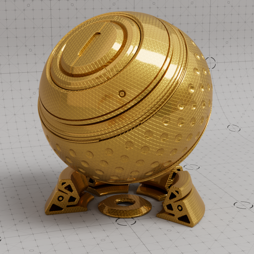
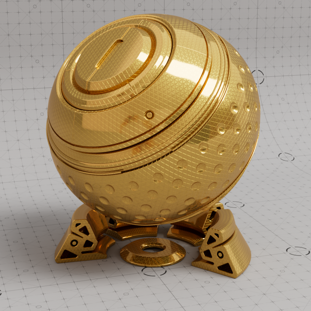
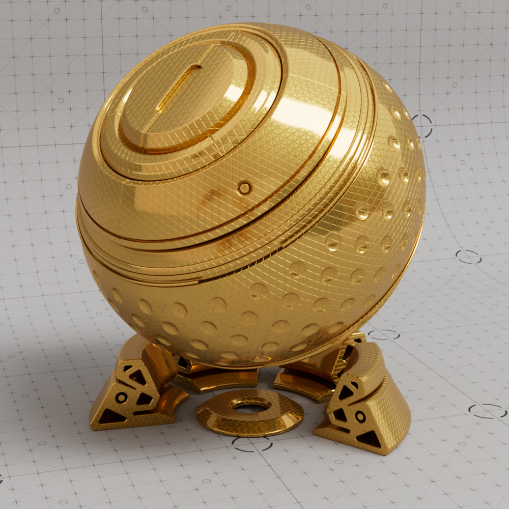
Enabled by default to ensure appropriate energy conservation on surfaces with high roughness values. When disabled, high roughness surfaces lose a lot of energy which may result in a very dim look.
|

|
|
|
|
|
| MMS Compensation: Enabled Metalness with high roughness |
Disabled Metalness with high roughness |
Enabled Transmission with roughness 1 |
Disabled Transmission with roughness 1 |
Enabled Transmission with roughness 0.5 |
Disabled Transmission with roughness 0.5 |
In order to apply the anisotropic roughness effect, the shader needs to know the orientation of the surface in u and v directions. These are the ways to specify this:
When this option is set to None, Redshift will attempt to compute an axis automatically based on the surface normal. This can be acceptable for simple flat surfaces, but can produce unpredictable results for other types of surfaces.
The vertex attribute channel name for UVs to drive the surface orientation for anisotropic reflections.
By default the default surface UV set is used. If you require separate control from regular surface texturing, you can define a different UV set here.
The vertex attribute channel name for Tangents to drive the surface orientation for anisotropic reflections.
Connect a UV Context Projection node here to enable inherited connections on all textures upstream from this node for simplified texture mapping. For more information, please see the UV Context Projection page.