Inputs
Here you can pass the geometry to be subdivided into the Node. Note that existing active selections will be taken into account in the process. Since only complete polygons will be subdivided, all points or edges of a polygon must also be selected when evaluating a point or edge selection in order for it to be subdivided.
If you want to limit the function of the Node to a selection, then select the element type of the selection here.
Here, if necessary, you direct the indices of the elements selected under Type into the Node that are to be subdivided. Note that only polygons are subdivided and therefore a point or edge selection must contain all elements of a polygon for it to be subdivided.
If you do not use this input, the Node automatically falls back to an existing active selection of the appropriate type. If this is also missing, all polygons of the geometry will automatically be subdivided.
Here you can, for example, use the name of a selection in quotation marks that you want to read out, e.g., "MySelection". Otherwise, the default entry will use an active selection on the geometry.
You can also use special keywords and logical operations here to create a new selection from scratch or a combination of already saved selections. The following keywords and operations can be used:
- Default: This term causes an active selection currently present on the geometry to be used. If no selection is active, all points will be used.
- odd: This term is used to select all elements that have an odd index number.
- even: This term is used to select all elements that have an even index number.
- all: This selects all elements of the selected type.
- hidden: Selects the hidden elements of the geometry.
- Name of a saved selection: If you enter the name of a saved selection in quotation marks, this selection will be read and used. To use a combination of a saved selection and another keyword or selection, use quotation marks with the selection name.
- Index numbers: You can also use index numbers directly, just as you are used to from the Index Array From String Node.
- Mathematical and logical operations: Mathematical or logical operations can be used to combine selections. Using the string odd – "center" for instance selects all odd elements and then subtracts the selection that has been stored by the name "center". You can use +, -, & (logical and), | (logical or) as well as a comma to combine multiple selections or index sequences.
Here you can select a subdivision method. You can select from:
- Catmull-Clark: This algorithm is also offered by the Subdivision Surface object by default. In this process, existing N-gons will be subdivided only after internal triangulation. If you want to export the geometry subdivided here (or the underlying LowPoly model) to other programs, this is the preferred method since Catmull-Clark is widely used and the smoothed shape will be approximately the same. To not only divide the geometry but also smooth it, activate the Smooth option.
- Loop: This type is intended for special pipelines (e.g. in game development). It is designed to handle triangles; if quads are included, they will be triangulated before smoothing. The subdivided, smoothed shape, in turn, consists only of triangles. The subdivision process is different from the normal Catmull-Clark types.
- Opposite: This subdivision type is identical to Catmull-Clark for quads. The only difference is in the subdivision of triangles, where one triangle then becomes two triangles and two quads.
This option results in the geometry not only being subdivided, but also being rounded. This effect corresponds to the function of the Subdivision Surface object and can therefore be used very well to create organic shapes from relatively low-resolution geometries. The mode setting for the UV coordinates can only be used if this option is active.
These values define the number of calculation passes on the Node, in which the geometry is subdivided one time each. If a square polygon is subdivided once in Catmull-Clark mode, four squares are created. After a further subdivision we have 16 quads. Keep an eye on this value, because the resulting polygon count and the associated memory and calculation requirements can quickly rise.
Provided that the geometry is smoothed by the Soft option, you can use this value to define a limit angle above which a hard edge will remain between the original geometry edges. If the Angle is less than the angle between the surfaces of the geometry, the geometry will remain unrounded despite the active Soft option. The Angle setting only affects the rounding between polygons, not at the open edge of a polygon.
If the geometry with active Smooth option is additionally rounded by the new subdivisions, the UV coordinates of the geometry can also be rounded. This corresponds to the functionality that is also offered on the Subdivision Surface object and helps to adapt the UV material projection synchronously to the geometry (see following figure).
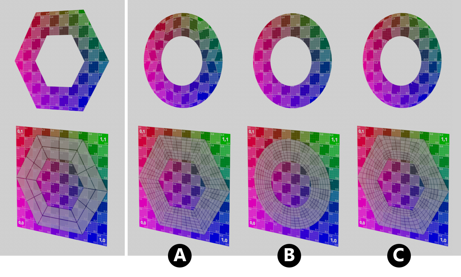 At the top left you can see the initial geometry, to which a regular raster texture has been assigned as the material (also visible directly below). The original UV coordinates of this geometry can be seen directly below. The three figures to the right show the results without UV smoothing (A), with UV smoothing (B) and with Fixed Border (C).
As can be seen on the left in the figure above, we are processing a simple Disc geometry here and have assigned a UV texture to it in order to be able to better observe the distortions of the UV projection due to the soft smoothing of the geometry by the added subdivisions. The texture tile used for this can be seen as a square area in the lower half of the image. Superimposed there, the unfolded UV polygons can be seen as a wire grid:
- A: If UV smoothing is switched off, the original structure of the UV projection remains unchanged and is only subdivided accordingly. This results in a deviation from the smoothed shape of the geometry, which leads to a distortion of the material projection. On the positive side, however, it must be noted that the part of the material assigned via the original UV coordinates remains unchanged. This can be helpful if UV coordinates at open edges of the geometry are to remain unchanged.
- B: With activated smoothing of the UV coordinates, the UV projection is also distorted to match the geometry. The material projection is thus retained on the surface, but can slip, especially at the edges of open geometries. This problem can be solved with the third mode (see C).
- C: The Fixed Border mode is shown here, which means that open borders on the geometry retain exactly the originally assigned UV coordinates. However, all UV points within a UV island are repositioned and interpolated between a smoothed and an unsmoothed position according to their distance from an open edge. This minimizes the slippage of the UV projection at the open geometry edges and at the same time adjusts the other UV coordinates to the new, smoothed shape as far as possible.