Object Properties
Lets you define the general height/size (when adjusting the height, the width is changed proportionally).
This is a path entry field and requires an Illustrator file (8 or higher or CC). Certain PDFs will work.
Clicking on this button will open the file in Illustrator, if installed.
If imported Generators are already provided with matching colors (tab Basic: Color), which are already sufficient for many things in the view, it is, of course, often necessary to assign real materials. If the option is activated: A simple material will be created for all Generators and automatically assigned. You can make these materials more complex if you want.
If the original Illustrator file is updated using the same name and path, the content will be reloaded. This has no effect on the settings below in the GUI.
This Offset value will set all objects to the defined value in the Z direction of the Vector object. Sorting according to layer, whereby each layer will be moved the same distance as the previous.
This value will move each individual path by the value defined. This is useful for overlapping paths, especially if they contain different colors. A very small value will prevent issues that can arise from two segments sharing the same space.
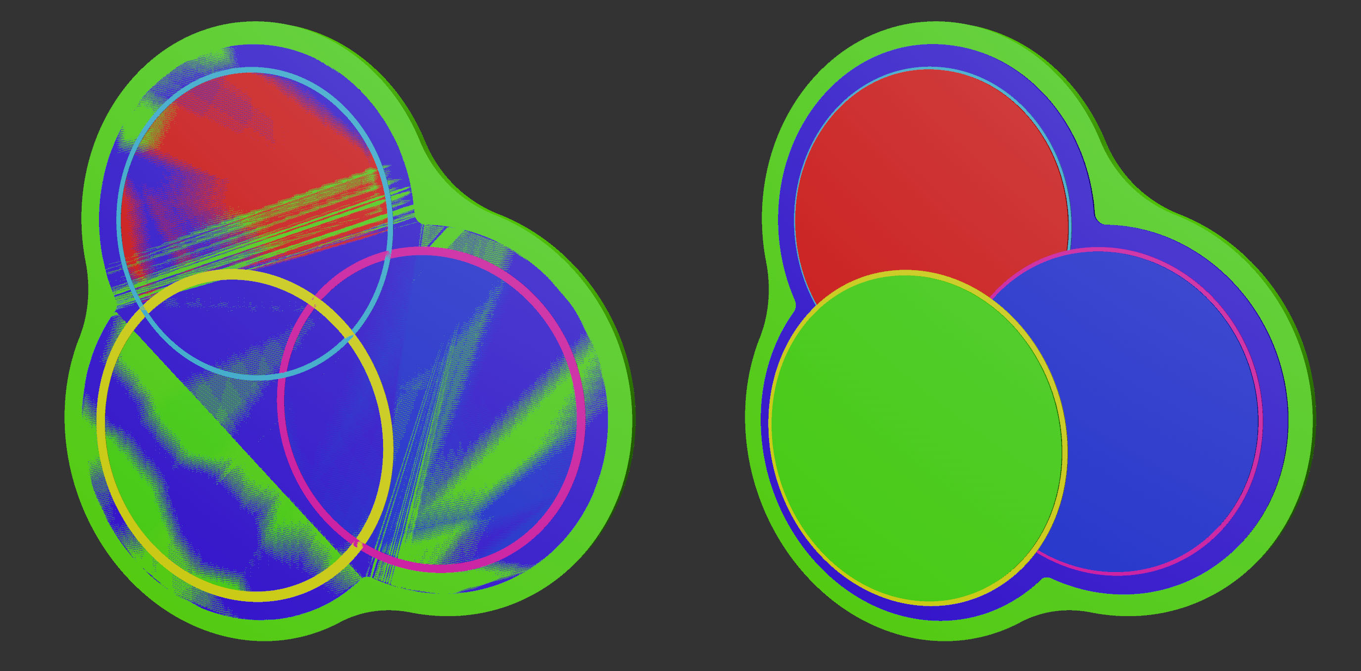 Different path spreads: 0 and 2.
All fill areas will be extruded with the same value. The missing subdivisions can be added individually later, after the Vector object has been made editable.
A bounding box of the content is used to determine the XY center.
After the path spread has been evaluated, a bounding box is used to center the group in the Z direction.
The Fill (Greedy) function can create unwanted elements on import. This can be managed using the Fill (Greedy) option. If it was not used on import, the missing files can be loaded using this option.
This option can be used to convert all paths to closed splines.
Force PDF affects the individual results (=specific file data). The modifications that are made during import can be undone in the Attribute Manager using this option. See also Force PDF.

The main parts of this section are settings that define a rectangular spline that is used as a cross-section of a Sweep object. Width and Depth define the size of the cross-section and Rounding defines the dative option of the rectangular spline for creating rounded corners.
This value defines the width of the rectangular spline (as seen in the direction of the surface extrude). Any values in excess of 100% can be defined. If the line in the Illustrator file was set to null it will remain at null. (A null value cannot be overwritten in a Vector Import object).
The Z size of the outline, whereby the Z axis is used for the Vector object (or put differently: the depth of the rectangular spline in the direction of the area extrude).
This value can be used to adapt the rounding 100% is the maximum size since the rounding depends on the Width and Depth and is restricted by the lesser of the two.
A complete per-Sweep object path reflects a value of 100% and will be scaled down to 0% along the path. Closed and open splines have different lengths. A value of 100% always represents the actual length.
This is the distance between the outline created by the Sweep object and the Extrude Front. Each additional volume that is based on Caps surfaces can require a new evaluation of this setting.
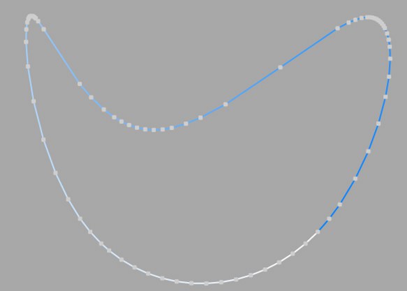
Here you set how the spline is to be subdivided during further processing. This is always important when you generate meshes with the help of generators. Depending on which type you select from the menu for Interpolation, you have further options.
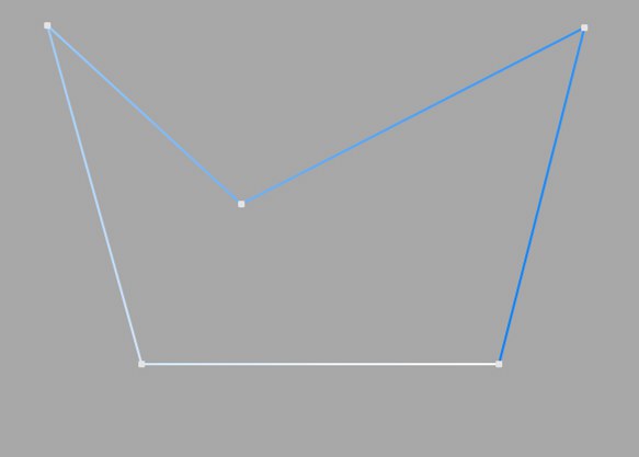
This type of interpolation uses the interpolation points of the spline directly and connects them via straight lines without setting additional intermediate points.
You cannot make entries in the fields for Points or Angle.
This type of interpolation divides the spline in such a way that a corresponding number of Points are used per interpolation point. The inserted points follow the natural course of the spline directly, i.e. they are closer together at support points than in between. The curve resulting from this interpolation does not necessarily pass through the interpolation points. If a spline has several segments, the value for Points applies to each interpolation point of each segment.
You cannot make any entries in the Angle field.
This interpolation type divides the spline so that the selected number of Points is used for each interpolation point. The points are exactly the same distance apart. The curve resulting from this interpolation does not necessarily pass through the interpolation points. If a spline has several segments, the value for Points applies to each interpolation point of each segment.
You cannot make any entries in the Angle field.
Opened spline: ((Points + 1) * (number_of_base_points - 1)) +1
Closed spline: (Points + 1) * number_of_base_points
This means, for example, that an open spline with four support points and a Points value of 2 is divided into a total of ((2+1)*(4-1))+1 = 10 points. If you close this spline, (2+1)*4 = 12 points are used. This procedure prevents, for example, a spline from being split more roughly after it has been closed.
This type of interpolation always sets intermediate points if the angular deviation of the curve is greater than the value entered under Angle. The curve resulting from this interpolation passes exactly through the interpolation points. If a spline has several segments, the value for Angle applies to each segment.
In contrast to the other interpolation types, different interpolations result if you change the interpolation point sequence of the spline.
The subdivision, also known as Adaptive, produces the best results in rendering. This is therefore the default Interpolation method.
You cannot make any entries in the Points field.
Subdivided is similar to the Adaptive type. In addition, intermediate points are inserted until the segments in between are shorter than the length defined under Max Length. This does not necessarily mean that the point distances correspond exactly to Max Length. Smaller values lead to higher quality, but as is so often the case, they also have the disadvantages associated with high point counts (slower redraw speed in the editor, etc.).
This enables significantly better rendering quality, especially with deformed text. If you enter the same value for Max Length as for Size in the Extrude object (Caps tab, Regular Grid option activated), you will get fairly perfect cap areas and edges without shading errors, as the subdivisions of letters and their caps fit together and triangles do not have to be inserted arbitrarily to connect the two mesh elements.
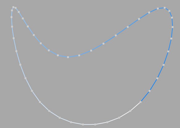
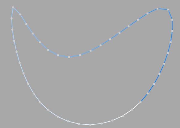
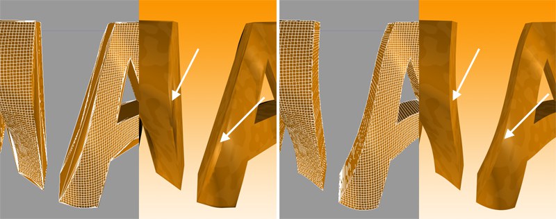 On the left Adaptive, on the right Subdivided Interpolation in combination with a Formula deformation object. Note the clearly defined edges on the right-hand side of the illustration.
This parameter, which is only effective in Subdivided Interpolation mode, controls the maximum spline segment length without an intermediate point (see above for Subdivided) must be inserted.