Display Menu
This menu contains the available quality levels and display options for UV elements in the UV Editor. Most of these options are also accessible via the Configure settings in the menu of the UV Editor and can, for example, help you identify problematic areas within a UV unwrap more quickly.
Filled Polygons
The unwrapped UV polygons are displayed with a colored fill, which may obscure any texture loaded as the background in the UV Editor. The edges of the UV polygons are only visible in Polygon, Edge, or Point mode.
Filled Polygons (Lines)
Same display quality as Filled Polygons, but with visible edges at all times.
Lines
Only the edges of the UV polygons are displayed. This ensures that any texture loaded into the background of the UV Editor remains visible everywhere. This mode is therefore particularly well-suited for aligning the UV unwrap with a background image.
Pins
The Add UV Pins option allows you to pin the currently selected points so that they cannot be moved by transformation or relaxation commands. When this display option is enabled, pinned points are highlighted in red.
Seams
Edges can be defined as Seams. A UV unwrap can then be automatically split along these seams, for example, while running the UV Unwrap and Relax command. Edges defined as Seams are highlighted in bright colors in the UV Editor and in the regular viewport.
UV Breaks
Mesh Boundaries
Open edges in the geometry are highlighted in bright colors in the UV Editor.
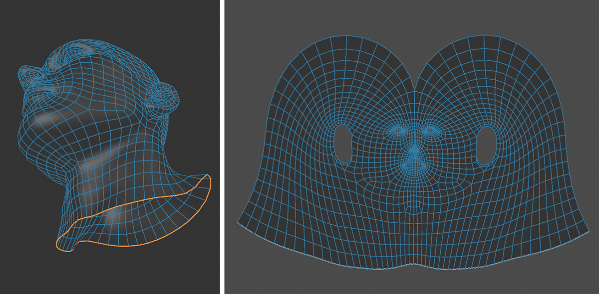 As can be seen on the left side in the display of the viewport, the head model is not closed at the bottom and therefore has an open edge. The corresponding edges can be highlighted in the UV Editor (see right side).
Highlight Connected Components
UV elements are often separated in the UV Editor and placed independently of one another, even though they are actually seamlessly connected in the geometry. With this option, a bright highlight indicates the elements connected to the currently selected UV points or UV edges.
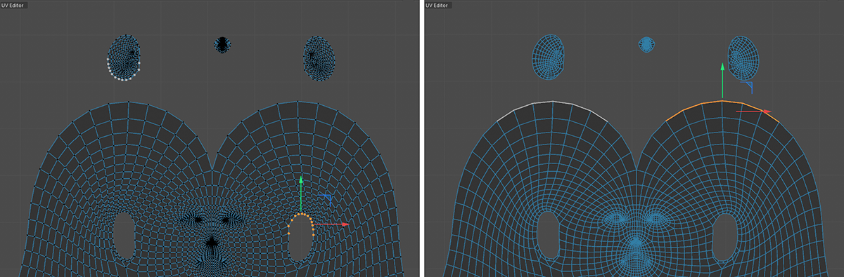 Connected elements can be highlighted. In the upper left corner of this figure, for example, you can see which UV points are actually connected to the selected points. On the right, edges have been selected. There, too, highlights indicate which other UV edges are actually connected to this selection at the geometry.
Overlapping Polygons
As a general rule, you should avoid having multiple UV polygons use the same UV value range—that is, overlap. Only UV polygons that can be identified individually and separately from other surfaces in the UV Editor can be textured individually. For this reason, this option also highlights such polygons in red to make them easier to locate for correction.
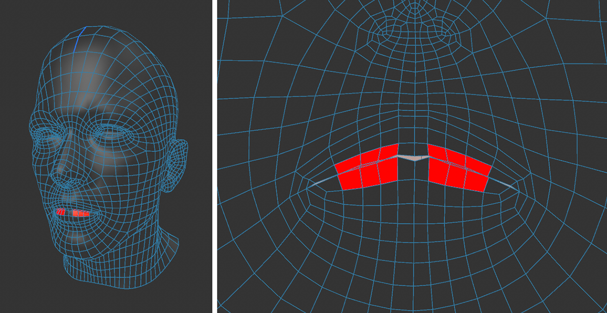 UV polygons that overlap at least partially are highlighted in red.
Multi-Color Islands
Cutting out selected UV polygons creates separate UV islands in the UV Editor. Assigning a random color to each of these islands can improve clarity.
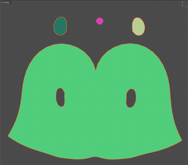 Random coloring to highlight the different UV islands.
Distortion
In many cases, it is desirable to shape the UV polygons to resemble the shape of the corresponding geometry polygons. This helps minimize distortion in the rendering of assigned textures. This color scheme highlights stretched areas in red, while compressed areas appear blue.
 Coloring based on the degree of distortion of the UV polygons.
Polygons Crossing Tiles
When assigning a single texture to an object, visible tiling may occur if the UV elements do not lie entirely within the standard 0..1 tile. However, even when using UDIMs to distribute textures and UV elements across multiple tiles, it makes sense to always place all UV elements completely within a single tile. UV polygons that lie on the boundary between UV tiles are highlighted in yellow by this option.
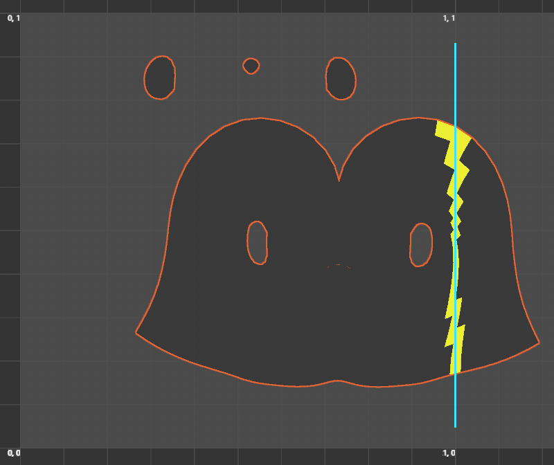 The blue line was added manually here to indicate the boundary between two UV tiles. The corresponding UV polygons are automatically recolored along this boundary.
Texel Density
The so-called Texel Density is an important measure, particularly in the field of video games. It indicates how many texture pixels are projected per object surface. There are essentially 3 reasons to care about Texel Densities:
-
Texture Resolution: If the Texel Density is too low, textures appear spongy when you approach them. If it is too large, the textures may appear crisp from close up, but you may be wasting valuable UV area.
-
Texture Homogeneity: In a scene, objects stand out that have a completely different Texel Density than their surroundings. This can disturb the immersion in video games, for example. It is therefore important to use similar Texel Densities in a scene.
-
Texture Efficiency: Video game engines tend to have limited memory and computing capacity, so it is important to keep the Texel Density as low as possible and still look good. This is why, for example, Texel Densities are defined for assets in video game productions, which employees must adhere to in order to ensure fast and high-quality texture display in all game situations.
To calculate the Texel Density for the UV polygons within the UV tile and display it in color, you must specify two values: the texture Resolution and the target Texel Density you try to achieve. You can do this using the two value fields located at the top right of the UV Editor.
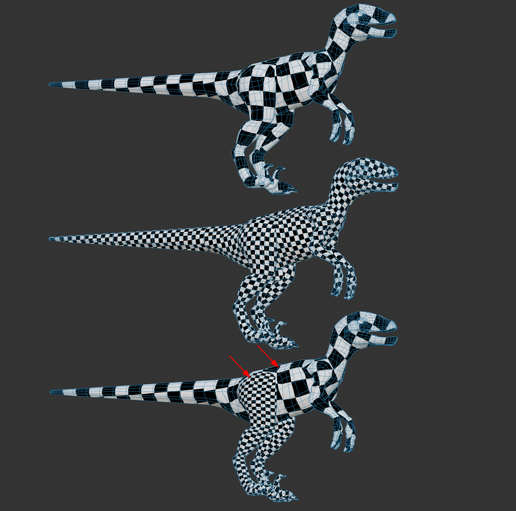 From top to bottom: smaller, larger, inhomogeneous Texel Densities (due to varied UV mesh).
Resolution
A map target size in pixels can be freely set here.
You will find a small menu on the right where you can select one of the common texture sizes (e.g. 2k, 4k, 8k corresponding to 2048*2048, 4096*4096, 8192*8192 pixels - textures are usually square corresponding to a UV tile).
TD
You will find a small menu on the right where you can select one of the common Texel Densities. To give you a rough guide, in the video game sector, there are roughly 3 different types of game in which the camera can generally get more or less close to assets. Choose the following Texel Densities, for example:
- First person (games from the first person perspective): e.g. 10.24
- Third person (games where the camera is placed behind the character): e.g. 5.12
- Top Down (games from which you look at the action from above): e.g. 2.56 or smaller.
In general, the closer the camera is to the asset, the higher the Texel Density should be. In a first person shooter, for example, you can get as close as you like to an asset, which is why higher Texel Densities are required here.
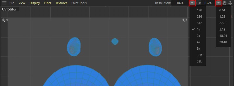 The two drop down menus and parameter inputs about the Texture Resolution of one UV tile and the Texel Density (TD) that should be enforced.
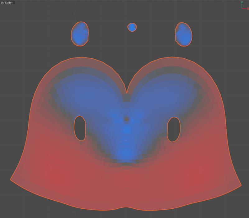
You can have the Texel Density displayed visually. To do this, enter a side length for your texture under Resolution (see value at the top right of the UV Editor) and the required minimum texture density under Target Texel Density. Based on the set Resultion and TD values the polygons in the UV Editor and in the 3D view are colored accordingly:
- Blue: Areas that exceed the Target Texel Density.
- Red: Areas that have a Texel Density that is too low.
- Gray: Areas that correspond approximately to the target Texel Density.
The colors are calculated according to the default settings as follows: If the Texel Density of a polygon is half the set value, the coloring is red; if it is twice the set value, it is blue. Intermediate Texel Densities are interpolated between these two colors.
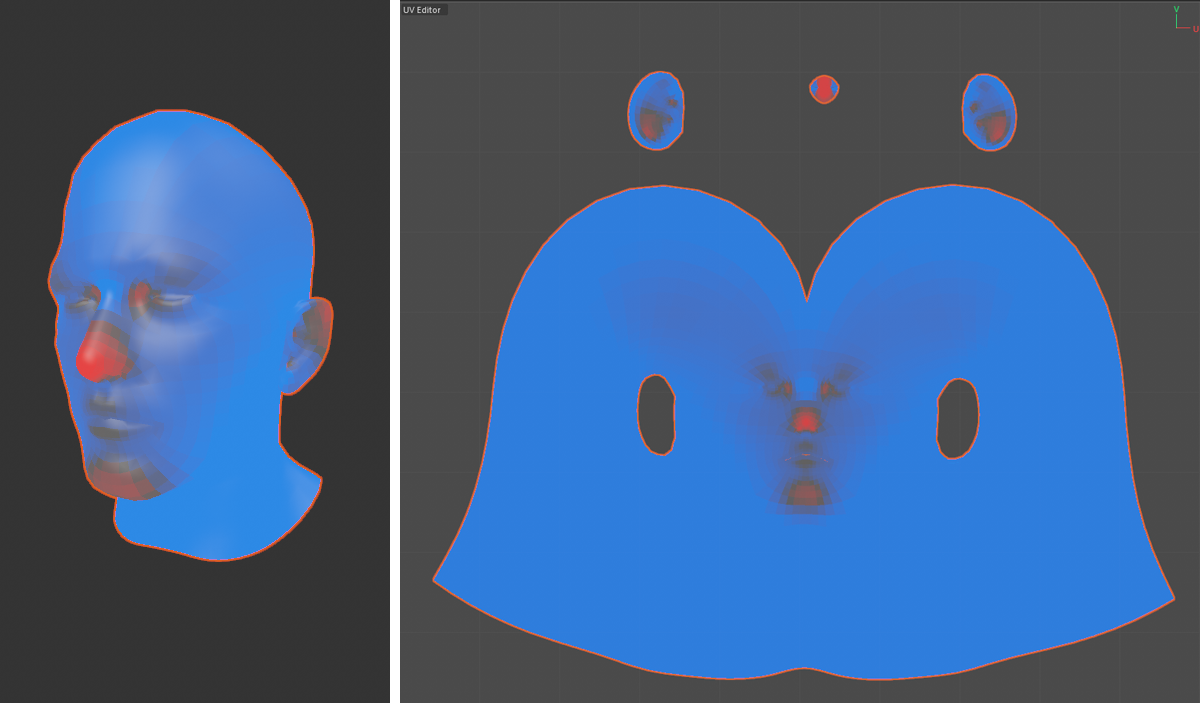 The Texel Density of the UV Polygons can be color encoded.
Using the Get Texel Density and Set Texel Density (selected) commands, you're able to transfer the Texel Densities between UV islands.