Relax UV
Relax UV gives you a different approach for optimizing the UV mesh. Unlike Optimal Mapping, which splits the UV mesh into groups of UV polygons, Relax UV attaches invisible springs that pull on the UV mesh to straighten it out and prevent overlaps. Click Apply repeatedly to pull harder on the UV mesh.
The command is applied to the selection or to the entire UV mesh if no UVs are selected.
In the example below you can see part of the UV mesh for a head. This UV mesh was created based on cylindrical mapping.
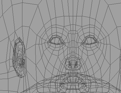 Before using Relax UV
The UV polygons are distorted and overlap in the areas for the nose, eyes and ears (left picture above). As it stands, this UV map is almost useless.
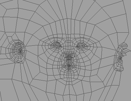 After using Relax UV
This is where Relax UV comes in. After clicking Apply three times, the UV mesh is now suitable for painting (right picture above). The distortions are greatly reduced.
The UV points at the edge of the selection are fixed in place.
UV points connected to unselected polygons are fixed in place. This enables you to untangle part of the UV mesh, such as the ear, without it being separated from the rest of the mesh. Free points at the edge of the selection are not fixed in place.
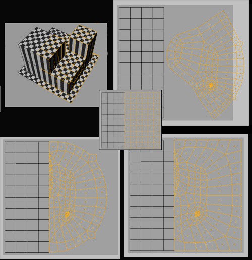 The original UV mesh (center), both options disabled (top right), Keep Neighbors enabled (bottom left) and Fix Border enabled (bottom right).
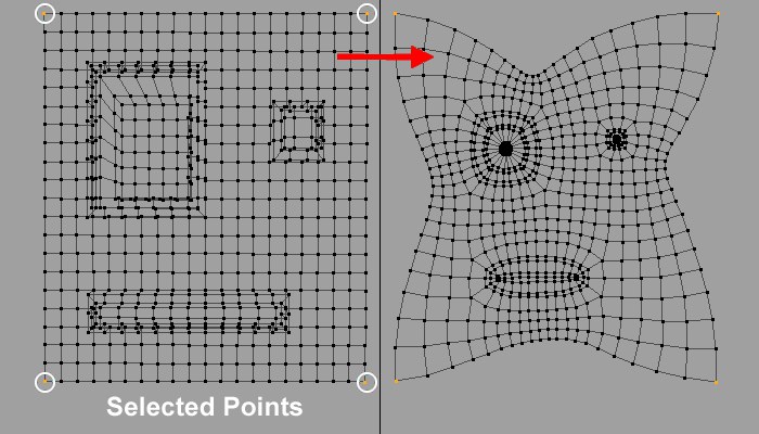
If you want to prevent certain areas from shrinking together or being twisted when relaxin UVs, select points that should be locked (pinned) to their current position and these UV points will not be moved.
The ABF mode can be described as an improved, but much slower, LSCM algorithm that produces fewer distorted UV polygons. It is advisable that a minimum number of Points be fixed via Pin Point Selection when using this mode.
ABF is better for use with organic shapes.
If the point selection should be read from a Selection tag, activate this option and drag the corresponding Point Selection tag from the Objects Manager into the field at the left of the option.
Example:
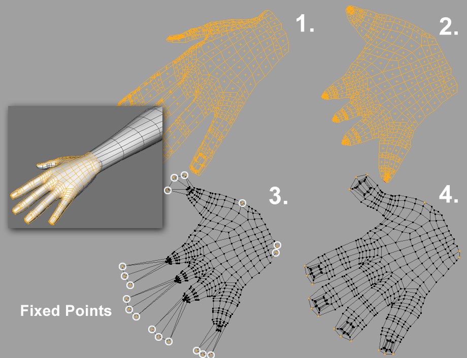 Workflow example for applying a UV Relax to a hand.
Let's say you want to paint this hand. After selecting the hand’s top surface and applying a frontal Projection (Projection tab), the result will look like hand 1. Many UV polygons overlap as a result of the projection. Click once on the Apply botton in the Relax UV tab (all other options are deactivated). The hand will be distorted, as shown with hand 2.
Although no UV polygons overlap, the finger tips have been compressed far too much to be able to work effectively in these areas. Switch to the UV Point mode and select the points of each finger and move them along the direction of the finger. Scale the points slightly for each finger and the result should look like hand 3.
Next, select all points of the finger tips and a few points on the wrist that lie on opposite sides of the joint. These points will now be pinned in place. To do so, activate the Pin Point Selection option. If you now click on the Apply button, the result will be as shown with hand 4. This result looks pretty good and only needs to be fine-tuned somewhat.
It is often necessary to define cuts using selected edges to avoid large UV-coordinate distortions. This process is also known as LSCM or ABF mapping (depending on the mode selected).
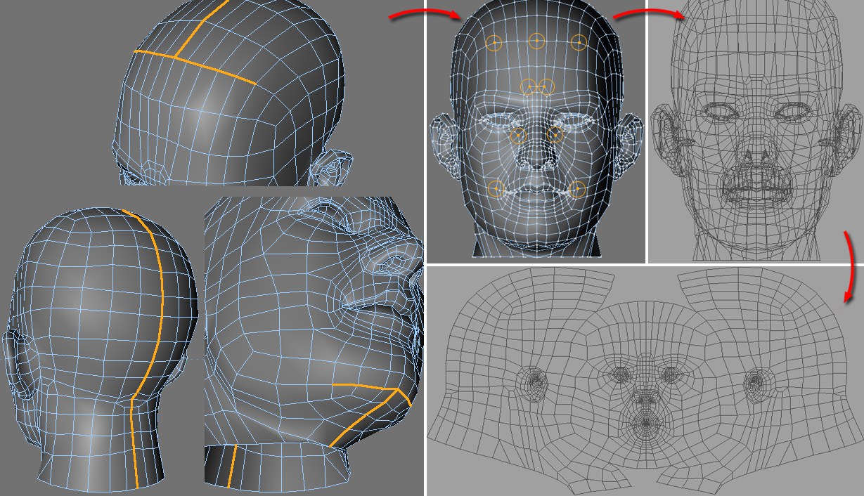 Head: © Bunk Timmer
In the following example a head’s UVs are relaxed:
- First, the edges along which the UV-mesh should be cut must be selected using Path Selection (located in the Select menu) in Edge Mode (Tools / C4D Tools / Edges).
- Next, switch to the UV Point Mode and select the points at the top (these areas will remain relatively unchanged after relaxing).
- Switch to the front view and create a fitting UV projection by clicking on the Frontal button in the UV Mapping Manager’s Projection tab.
- Go to the Relax UV tab and activate the Pin Point Selection and Cut Selected Edges options. Also activate Auto Realign to make sure the relaxed mesh fits the texture. Click on Apply to see the results.
If the edge selection should be read from a Selection tag, activate this option and drag the corresponding Edge Selection tag from the Object Manager into the field to the left of this option.
- If a frontal projection is applied to a spherical object the algorithm will not be able to locate suitable UV mesh edges. In such instances, the UV mesh should be broken down into several parts (e.g., using Cut Selected Edges).
- If triangles or squares have been created too thin or are very degenerated (i.e. polygons lie on a straight line).
- If a polygon edge borders on more than two polygons.
In this and the previous case, the two will select problem polygons so that such occurrances can be quickly located and edited accordingly.