UV Edit Menu
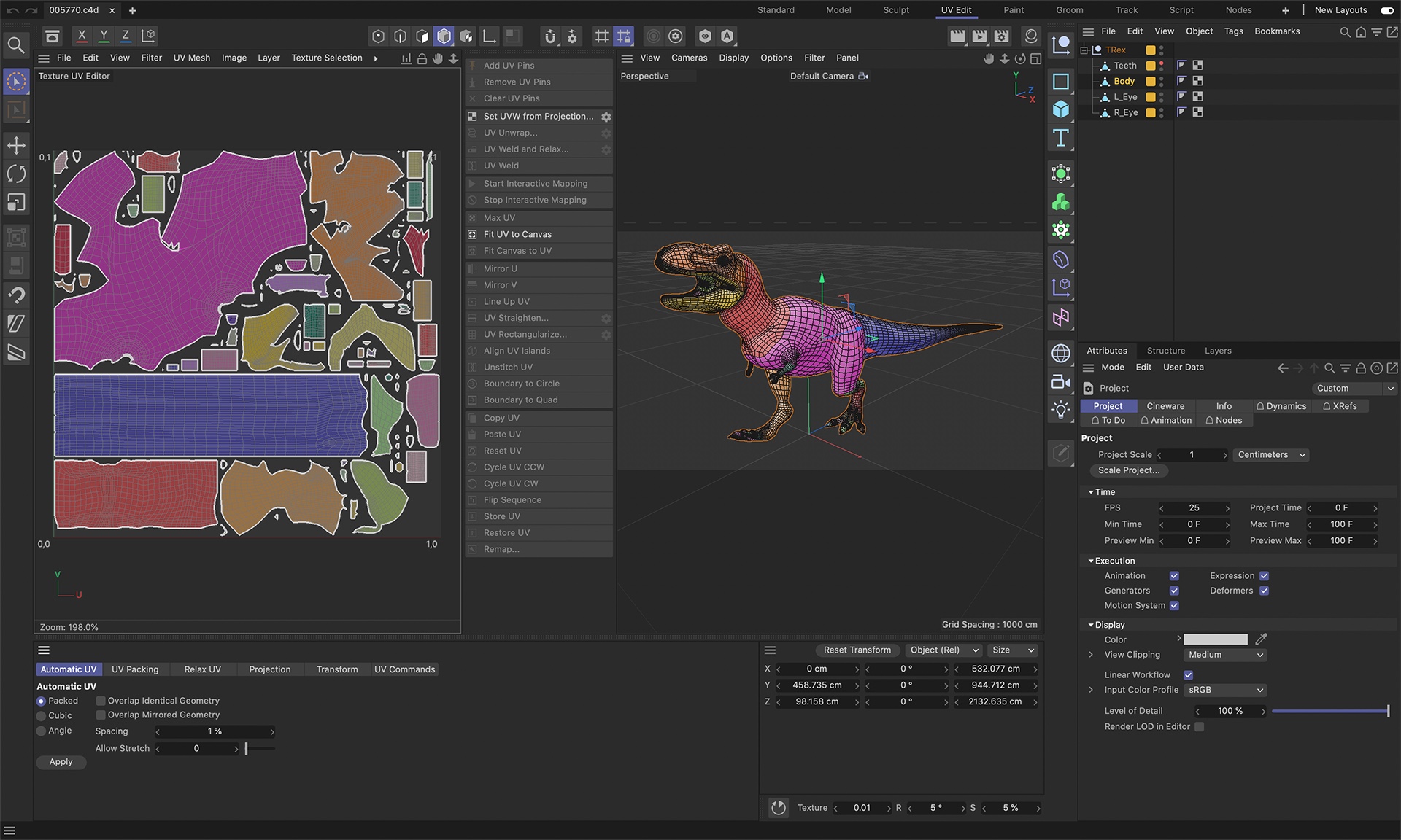
The default layout for UV editing.
The Texture view boasts a powerful integrated UV editor which enables you to create a high quality UV mesh for any shape of object.
Before you can edit the UVs, though, you must ensure the object actually has UVs (you can have BodyPaint 3D generate these if required). Also, the object’s texture must use UVW mapping.
Two key advantages of UVW Mapping are:
- UVW Mapping prevents texture slippage so that when you deform such as a flag flapping in the wind the texture will keep in place.
- UVW Mapping, in conjunction with the UV editor, offers the most advanced way to paint your textures. You can see and edit the UV mesh in two dimensions. You can select the UV polygons that make up the UV mesh and edit them as required.
For example, suppose you want to paint a moustache on a head model. However, the UV polygons are too small (i.e. cover too few texture pixels) to allow you to paint hair without pixelation. One solution is to select the UV polygons for the moustache, move them to an unused part of the texture and scale them up. The UV polygons will then cover more texture pixels, enabling you to paint more detail than was possible in the previous position on the texture.
There are also commands which enable you to optimize the UV mesh and rid it of overlapping. In short, the UV editor offers all the tools you need to create a superb UV mesh for trouble-free painting.
Let’s assume you have a great number of objects, Texture and UVW tags in your project. Since only 1 texture (but multiple texture views) can be displayed simultaneously, the following rules apply:
Simply select the respective object. If it has multiple UVW tags or Material tags, those at the top will automatically be used. If other tags should be used, simply select the respective UVW or Material tag (which will automatically use the neighboring UVW tag).
Multi-editing of UV meshes
New in Cinema 4D is the ability to display and to edit multiple UV tags simultaneously. In the UV Editor, all UV meshes of all selected objects or UV tags are displayed.
The most important UV display modes, selection and transformation tools as well as the Geometric and Rasterized settings in the UV Manager’s UV Packing menu work for multiple UV meshes. Other commands and tools will not necessarily work. These will be grayed out and can therefore not be used. You can then select an individual element (object or UVW tag) to make these available.
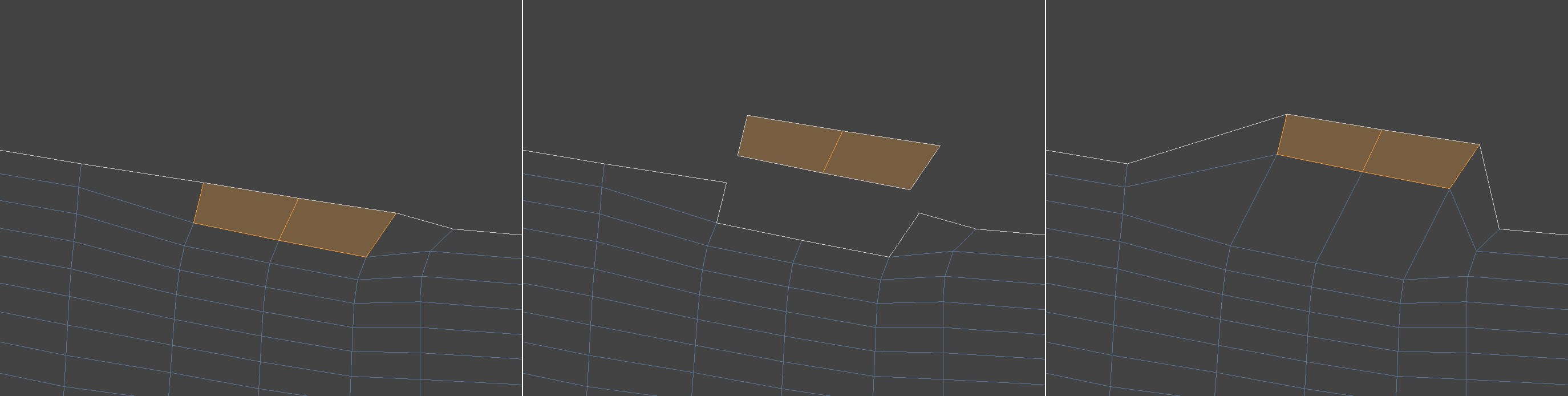
Note that the UV points of neighboring UV polygons exist double on the borders. It may look like the UV polygons share common points (as is the case with polygon meshes) but the UV points lie congruently. This is why you can simply remove UV polygons from a UV mesh using the Move command (center image). If you want the normal polygon mesh behavior, you can, for example, enable the Move tool’s Keep Face Neighbors option. The result can be seen at the right of the image above.
The following applies to selections:
- If a UV edge is selected, only the UV points of the UV polygons for that UV edge will be selected
- If a UV polygon is selected, only the UV points that belont to this polygon will be selected
- It will be difficult to select only a single UV point if two lie congruently. In this case you select the UV points of two neighboring UV polygons.
What is a UV mesh?
If your object has UV coordinates, a UV polygon is assigned to each object polygon. The UV polygons have their own independent coordinates (on the texture bitmap) and together they form a UV mesh.
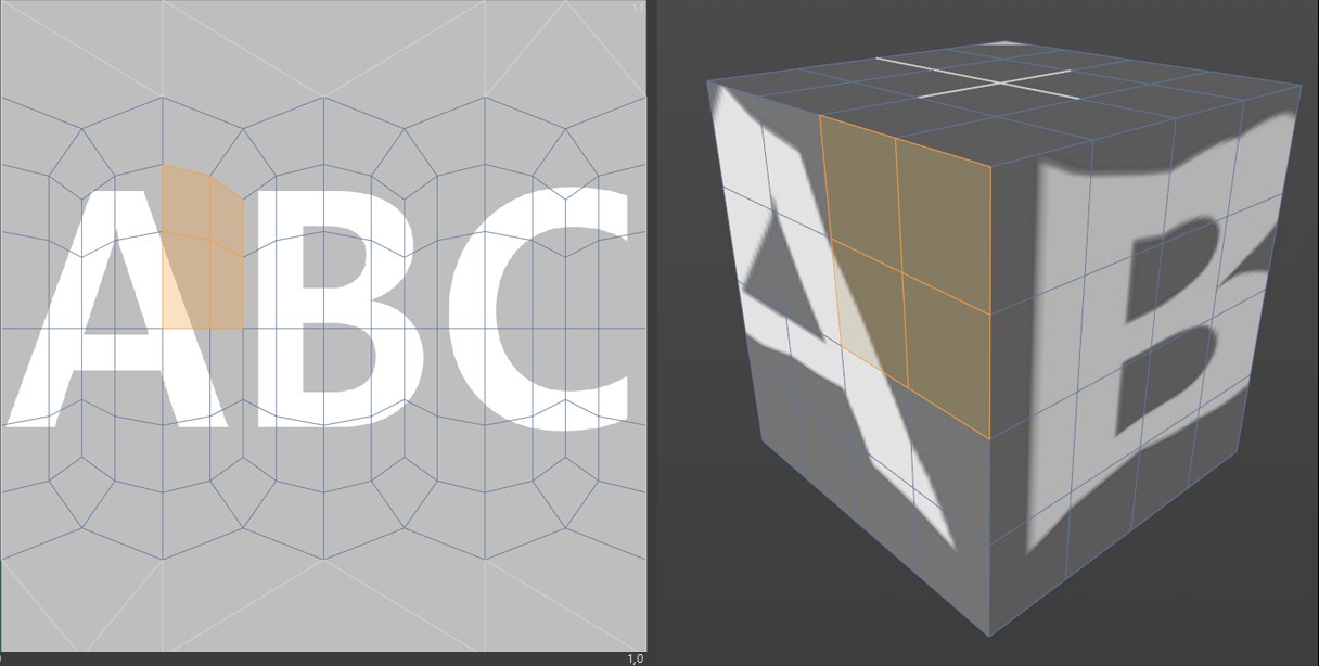 Figure 1. The 3D view and the Texture view for a cube with spherical mapping. Some of the object polygons are selected.
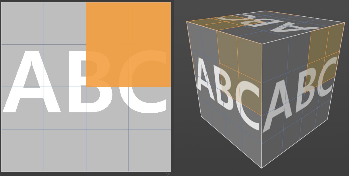 Figure 2. The 3D view and the Texture view for a cube with cubic mapping. Again, object polygons are selected.
Note how each polygon is allocated its own UV polygon in the Spherical Mapping example. As a result, you can paint each side of the cube separately.
In Figure 2 (Cubic Mapping), you can see that there are no separate UV polygons; the sides cannot be painted separately, because the texture has been applied six times, once to each side. Brushstrokes applied to one side are applied to the other sides automatically.
However, the example exposes one of the shortcomings of Spherical Mapping: The UV mesh is heavily distorted near the top and bottom. These areas are at the poles of the spherical projection.
This distortion is caused by the fundamental principle of projection: a two-dimensional surface (texture) must be placed onto a 3D object. Distortion is inevitable. Think of trying to wrap your child’s favorite Pokemon™ sticker around a baseball. Maps of the world face the same problem. For example, Greenland appears to be larger than the United States on a map. In reality, the United States is more than three times larger than Greenland. Distortion happens when a sphere’s surface (such as that of the Earth) is represented in two dimensions.
Nonetheless, you can paint your object free of distortion using projection painting.
What can I do if the UV mesh can’t be edited?
- Make parametric objects editable (select them and press the c key)
- Convert Generator objects to polygons (select them and press the c key).
- Create a UVW tag if there is not one already (Object Manager: Tags / Generate UV Coordinates).
- Select the UVW tag and in the Attribute Manager, ensure that Lock UVW is disabled (Tags / Create UVW Tag / Material Tags/ Generate from Projection).