Resource Editor
![]()
General
The Resource Editor is used to configure user interfaces for nodes. You can define a range of file types that should be shown to the user in the Material Editor when the Node Material is edited. Various strings for different language versions can also be saved.
An example of how this can be applied can be seen in the Uber Material, which is a material based on nodes but offers the same information as the default materials in the Material Editor.
The different groups and parameters for these settings were defined using the Resource Editor.
If you already have a Node Material or Node Shader open the Node Editor, you can right-click in the Node Editor and select Edit Resource to open a separate Resouce Editor window.
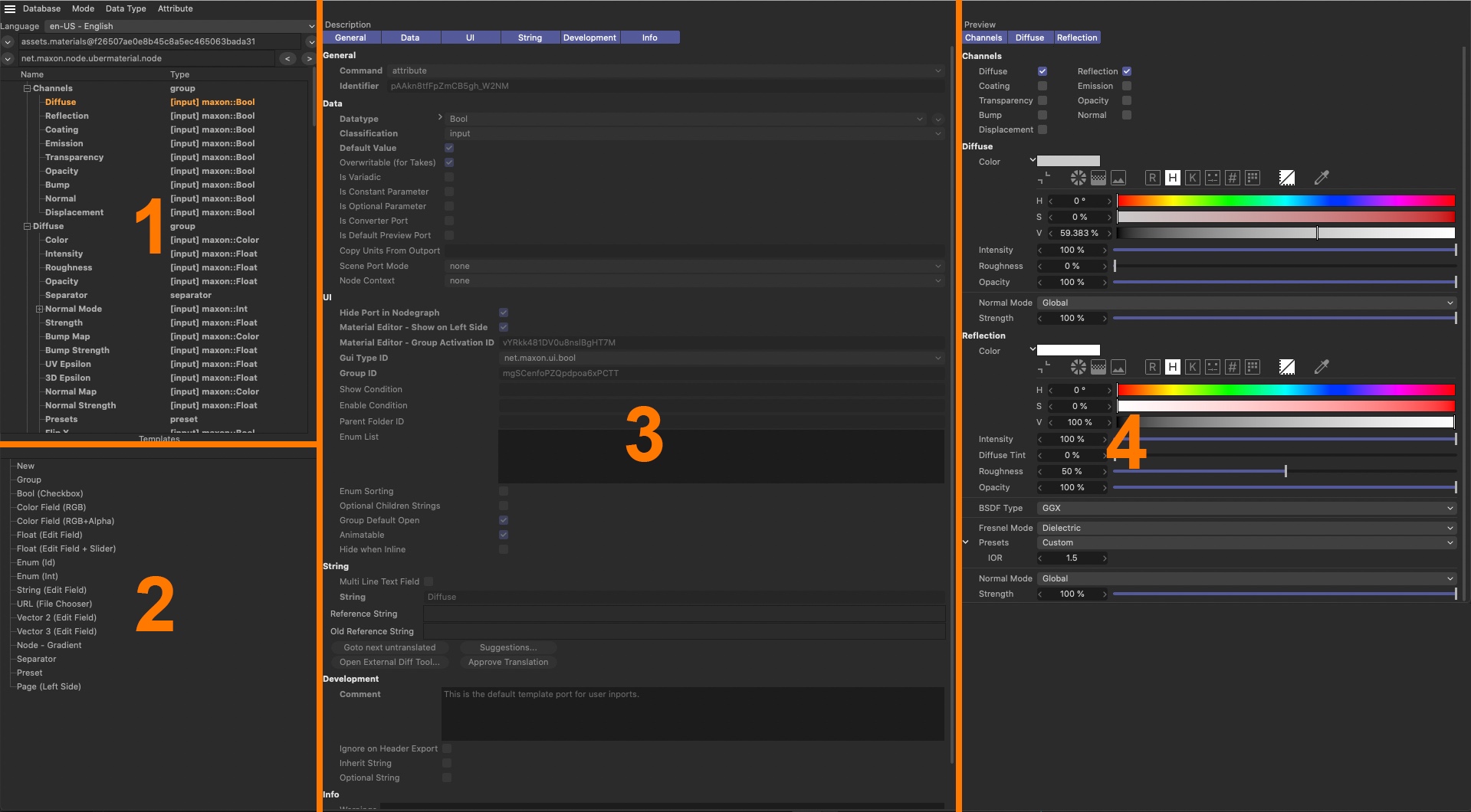 Next to (1) you will find an overview of all existing attributes and properties. In the Template area next to (2) you will find a list of common file types for new attributes and commonly used sorting elements (groups and separators). At the center of the Resource Editor next to (3) you will find the settings available for the selected attribute. Finally, at the far right next to (4) you will find an integrated Attribute Manager where ports, attributes and properties can be checked in their display and function.
The Resource Editor is divided into different areas. At the left is a column with an overview of the existing attributes and file types as well as those you added yourself. The priniciple is comparable to adding User Data via the User Data menu in the Attribute Manager. The entries can be organized into groups.
The bottom section of the left column shows templates. These are the default Cinema 4D file types and user interfaces for input that can also be used for custom parameters. Here, you will, for example, find color fields, text input fields and option check boxes. Elements can be easily dragged and dropped from the templates directly onto the area above.
The center column of the Resource Editor shows a description of the currently selected parameter. Here you can, for example, activate the permissible minimum and maximum limits for numeric values or the use of a slider in the interface. More uinique attributes such as if a parameter should even be visible or the units that should be used can also be defined.
The right column of the Resource Editor shows all activated parameters and attributes of a given node, as would be displayed in the Attribute Manager or Material Editor.
Workflow example
In many cases you will first create a new Node Material and open it in the Node Editor. Now you can construct a material with the help of various Material Nodes or at least mull over the most effective inputs for your material that can be used to control its look. In simple cases, these can, for example, be color values or brightness that can be defined or how textures and other numeric values can be linked in order to control intensity.
The more complex a material’s attributes, the more it makes sense to simplify the material’s modification and use in order to be able to use it for future projects. What this can look like can be seen in a Cinema 4D Uber Material. This is a normal Node Material that does not have to be modified using the Node Editor but with the known Material Editor after you double-click on it.
Select all of your material’s nodes and group them. You can use the shortcut alt+g or the Group Nodes command in the Node Editor’s Create menu, which is also available as an icon at the top of the Node Editor.
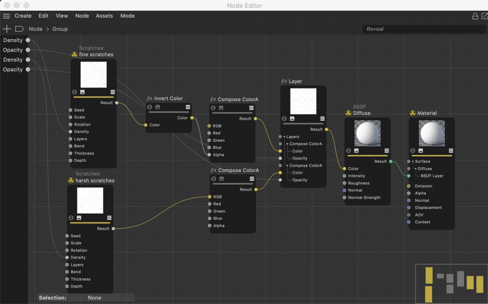 After the material nodes have been grouped you can add ports on the left edge of the node graph that is made available to the user in the Attributte Manager or the Material Editor. This is done most easily if you drag the node’s respective input ports onto the left edge of the node graph.
Then open the new node group by clicking on the arrow icon below the group node’s preview area. You can now see the Material Nodes again where you can edit them or easily add nodes. You can also add groups within a group, which can help maintain an overview when working with complex materials.
Whenever you want to pass data to the nodes within the group that should be editable in the Material Editor, simply add an input port within the top-most node group. This can be done in different ways:
-
The simplest option is to drag and drop the input port that you want to make available in the user interface onto the gray stripe on the left of the node area in the Node Editor. A context menu will appear in which you can select Propagate Port.
A new input port will be created that is linked with the port from which you just dragged. The new input port will automatically assume the name, default values and data type of the original port. -
If you want to create an input port that is not connected to a port within the Node Material, simply right-click on the gray bar at the left of the node area in the Node Editor and select Add Input > Add New Input. This will create an input port for the group that has no value or data type or connection to any nodes. This can be useful if you already know which data will be passed to the material but haven’t yet fully defined the Node Material, and not all nodes are ready to be linked to the input ports. The default value, data type and type of user interface for this manually-created input port can be defined using the Resource Editor. To do so, right-click in the Node Editor and select Edit Resource. In the left column of the Resource Editor you can then add a new port, select it and configure it.
- A third option for adding input ports to a material is to open the Resource Editor and drag a data type from the templates directly onto the editing area for inputs just above or to select Add Attribute from the Resource Editor’s Attribute menu.
After the desired inputs have been added, their data type and attributes will be adjusted in the Resource Editor, if necessary, and configured in accordance with the user interface. We will cover these options later.
After all input ports have been created and linked to the respective inputs of the Material Node in the group you can exit the group display by reverting back to the material’s node layer in the Node Editor’s tree view. Select the group node and then select Start Node in the Node menu. This command is also available as an icon in the Node Editor’s icon menu.
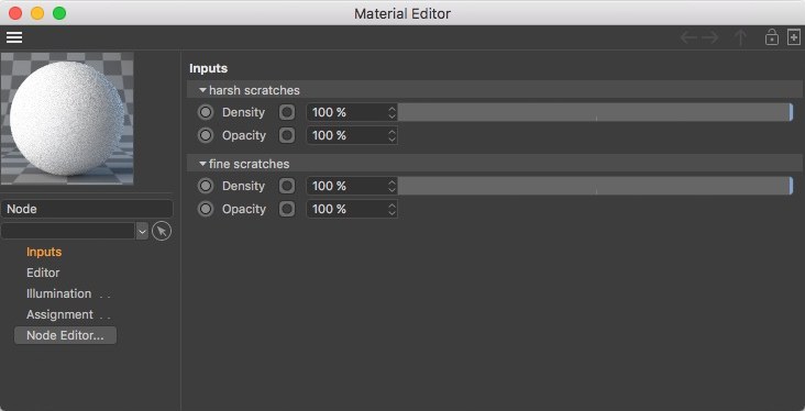
If you double-click on the Node Material in the Material Editor, the Material Editor (and not the Node Editor) will open where you will find the input ports that were created.
If the material is so good you want to use it for other projects, you can save it as an Asset with a unique name. It can, for example, then be saved to the preset menu for materials and easily accessed via the Node Editor’s Asset section.
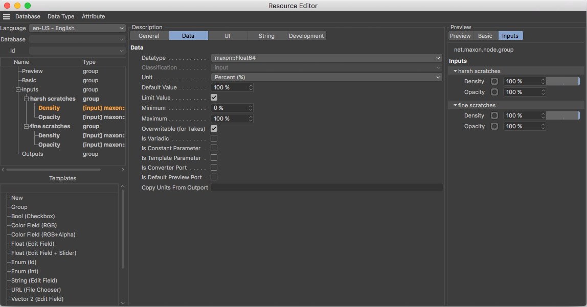
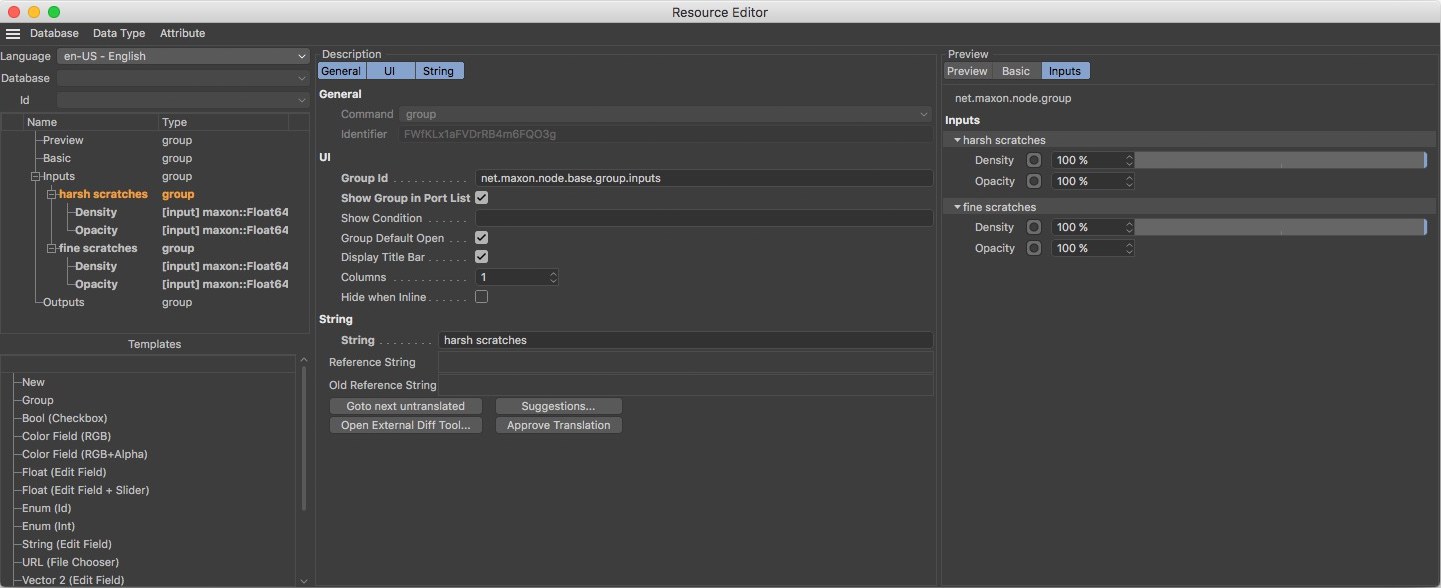 The Resource Editor can be used to edit data types, graphic user interfaces and the names of ports that are created. New ports and attributes can be created and organized in groups. The result can be checked right away at the right of the Resource Editor in an Attribute Manager. This image shows the settings for the respective group in which ports can be organized for an optimized workflow.
Material Resources
After a Node Material has been opened in the Node Editor and the Resource Editor has been called up you will find elements that each material already has. This includes a Preview section, which consists of both preview renderings that show several funtions of the Material Node and the material as it looks in the end.
A Basic section is also available where you can define unique names for an asset or a group.
Below the Name field you will find an Asset Version selection menu, which can be used to more easily manage edited versions. When a node group or asset is configured for the first time in the Resource Editor you can only select Latest as the Asset Version.
The remaining settings in the Basic menu are more cosmetic in nature. Enabling the Custom Node Color option will let you assign a custom color to the asset using the Node Color setting.
The entries for Inputs and Outputs represent all input and output ports for a given group or asset. Here you can subordinate your own ports, if necessary, but you can’t modify any of the settings.
Presets
All of the following settings for the individual user data and ports of a given group or asset can be configured in different languages so the correct translation is displayed if you switch to a given language in Cinema 4D. As a rule, English will be used for the default installation. In addition, you may also have German installed. In such cases it makes sense to first make all settings for the universal English layout and then modify the namels of the settings for German (or the target language).
Language
Select en-US - English as the base language for Cinema 4D to create and name all required user data and ports. After this is done, switch to de-DE - Deutsch in this menu to enter German terminology for these settings. If additional languages are installed, this process can be repeated for each of these languages by simply switching to the desired Language. If language versions exist for which strings have not been translated, these will be marked by a symbol with a small warning sign (see this example)
Database
The data from different application parts, modules or plug-ins are saved in separate databases. These databases are logged in automatically when the application is started and will be made available for use.
ID
Internally, objects are differentiated using unique numbers called IDs. The respective objects can be selected from this drop-down menu. If an object is edited via the Resource Editor, the database and respective ID will be blocked.
Creating and managing attributes
As a rule, you will not use a single setting to define material properties but several settings that should be grouped thematically. This is the sampe principle as with other materials, e.g., where grouping is used to define material properties so properties for color, bump, reflection or displacement can be arranged in separate groups for a better overview and workflow. There is also the option of making some of the settings available only optionally. For example, the calculation of the displacement or lighting may not be necessary in every material. Accordingly, these settings can then only be displayed if needed. As a rule, Cinema 4D uses a list of options in the left column of the Material Editor where the optional material channels can be enabled.
Group
A group can be used to combine several inputs and to define layout options for your settings.
The Resource Editor offers exactly this possibility through the use of groups in which you can organize user data and properties. The simplest option for creating a group is to drag the Group setting from the Template field into the field above.
 Groups make it easier to organize settings for display in the Attribute or Material Managers. In this example, the settings for rough and fine scratches are managed in two separate groups in order to better separate the identical port names.
General
Here you will find settings that normally result directly from the type of selected property and therefore cannot be edited.
Command
Here the type of the selected property is displayed. For a group, ,group’ will be displayed or an input value ,attribute’. For other special types of properties it can be a Command such as ,separator’, which simply creates a dash in the user dialog to make the text easier to read. The Command ,preset’ can also be used for an element from the preset menu such as a Fresnel refraction index.
Identifier
Each property has a unique Identifier made up of a series of letters, characters and numbers and is assigned automatically. Using this Identifier, a relation between groups and attributes can later be made, e.g., to display groups only when a specific activation option is enabled. An Identifier can itself not be edited or selected in the text field but you can right-clickk on an Identifier’s name and copy the selection to the cache and paste it to another location.
UI
In this menu you will mainly find options with which you can define the display of the selected property and the layout in the Material Editor.
Group ID
If desired, you can enter a custom Identifier here for the group. This can be any combination of lower-case letters, points, underscores and numbers. The group ID can, however, not begein with a number. Furthermore, you should not use upper-case letters.
If this field is left empty, the Identifier from the General settings will automatically be used.
Show Group in Port List
Only if this option is enabled will the groupt itself be listed in the Node Editor’s port list. This method of control can be used independently of the group’s elements. Disabling this option will leave the display of the settings in the group unchanged in the port list.
Show Condition
The display of the group can be made dependent on the options. To do so, simply enter the name of the respective option between the wavy brackets in this field. Examples of what this can look like: (Checkbox) or {Value}<5.0 ; {Text}=="text" ; {Enum}=="enumvalue". In addition, a formula parser is also behind this function that also permits bracket terms. Alternatively, the Identifier of the respective option can be copied and pasted.
Group Default Open
As known from the XPresso user data, groups of settings can be opened and closed by clicking on the small triangle next to the setting. If this option is enabled, the group will be displayed opened by default so that all suburdinated entries are visible in the port list.
Display Title Bar
By default, each group starts with a title bar with a different brightness in which the group’s name can be seen. If you don’t like this type of display, simply disable this option. The settings contained in the groupt will then no longer be displayed indented in the Attribute Manager.
Columns
This combination of numbers defines the number of columns for this group. With two columns, for example, up to two properties will always be displayed next to one another.
Hide when Inline
This option hides a setting and its value and interface will no longer be displayed if the corresponding object is opened in a link field in the Attribute Manager.
Text
See Text.
Defining attributes
Attributes make up the actual parameters and settings that you want to make available to whoever is using the given material. In order to more clearly present attributes and to do so in a more attractive layout, the Group element can be used, which can also be used, among other things, to create a two-column display in the Material Editor.
A new attribute can be created in one of several ways. You can either drag the desired element from the Template field into the field above or you can select Add Attribute from the Attribute menu. Attributes are available in a variety of data types. It therefore makes sense to consider which data type you want ahead of time.
 An attribute’s or port’s data type define the type of input as well as the controls. This is why it is very important to pay close attention to the data settings of a given property. The most common data types can be called up as presets via the Template field or from the Attribute menu.
Data types
An attribute’s data type defines how this property will subsequently be displayed, evaluated and operated by the user. A color, for example, uses different settings than does a text field. The controls will be correspondingly different. Let’s take a look at the most common data types for settings and attributes as they can be found in the Templates field:
- Bool: Makes an option field available that only recognizes the states on or off. This element is well-suited for enabling properties and can, for example, be used in a material’s channel list.
- Color Field (RGB): Also referred to as Color. Offers the possibility for creating a color value using the known RGB or HSV sliders. The expanded data types Color Field (RGB+Alpha) and ColorA offer the same input possibilities but adds an alpha percentage value.
- Float (Edit Field): Also simply referred to as Float. Offers the possibility of inputting float comma values. If Float (Edit Field + Slider) is selected, an additional slider will be available next to the numeric value.
- Enum elements can be used for more comprehensive selections and make a drop-down menu available from which a selection can be made. For example, think of the selection possibility for a Fresnel preset in a material’s reflectance. A comparable function is also possible using the Data Type Int that can be selected when adding custom attributes. Enum elements can only contain lower-case letters, undercores and numbers, whereby a number cannot be used as the first character. In the overview window for the settings you can open the Enum element where you will find the entries from the Enum list. If these are selected, strings and translations can be made for these.
- String fields can be used to input texts.
- Url (File Chooser): Also referred to as Url. Makes an input field and a button available for defining a file to be opened or a save path. This element can, for example, be used to load a texture within a material.
- Vector 2 (Edit Field), or Vector 2D, makes it possible to input a two-dimensional vector with which, for example, the position of a pixel within a bitmap can be defined.
- Vector 3 (Edit Field), or Vector, is a three-dimensional vector that, for example, can be used for inputting positions or directions in 3D space.
Data
This group of settings can be used anytime to modify the Datatype of a selected attribute or other setting, e.g., to unify or limit a value range.
Data Type
Here you can read out or switch the current Datatype.
Classification
This setting defines the type of attribute. Once you’ve selected a Classification, this selection cannot be changed. The Input option should be selected as a rule so an input port is created with which the value entered by the user can be passed to the material. Alternatively you can select the Output option which will also create a port but on the output side of the group or asset. This way, user-defined values can also be gotten from the node group. A third possibility is the Data option, which will also make the configured attribute available for the user as an input but will not create a port.
If None is selected, the attribute will remain unspecific.
Unit
Here you can define the desired unit, e.g., a numeric value. This unit determines, among other things, if this numeric value is an angle or a unit of measure, for example. You can select from the options Percent (%), Degree (*), Meter and Time. If None is selected, the numeric value will remain without a unit.
Default Value
Here you can select the color, setting or value that should be used the first time the dialog for this setting is called up. This ensures, for example, that a material will show a result, even if a user has not yet defined all settings. The Default Value format changes depending on the Datatype selected. For Boole settings, only one option will be offered; for colors a color field; for float settings a numeric field, for example.
Limit Value
Enabling this option will make additional input fields available that can be used to define admissible maximum and minumum limits for values.
Minimum / Maximum
Depending on the Datatype and Gui Type ID selected, separate definitions can be made between which user inputs have to remain. Small values will be increased to the defined Minimum and larger values will be restricted to the defined Maximum.
If the Gui Type ID net.maxon.ul.enum is used, the Datatype can also be restricted to the respective Minimum and Maximum values that were defined.
Enum List
This element is available if Datatype is set to Into or Internedid and lets you create an individualized list of elements that will be offered as a menu for the attribute. If Datatype is set to Int, fill the list with Identifier names of the menu entries and set a colon for each followed by a sequential number.
Overwritable (for Takes)
If enabled, this value can also be overwritten using the Take system in Cinema 4D.
Is Variadic
If enabled, the Number of Variadic Ports setting can be used to assign any number of sub-values. Commands can be registered in the Variadic Commands field, which will then appear as buttons such as Add or Delete and will have to be executed in their function as a command code.
Is Constant Parameter
If enabled, this port can only be assigned a static value. The value cannot be modified during rendering, for example. A port cannot be connected with the output port of a color gradient or noise node, for example.
Is Template Parameter
If enabled, the variable will be marked as a Template Variable, as is also the case the also exist in C++. This type of variable has no defined datatype and can be used to dave static values. A typical example would be a variable for π, which is read out as the flowt 3.1415 … and simply as 3 as an integer.
Is Converter Port
If enabled, other Datatypes linked to this port will be converted to the port’s native format, if possible.
Is Default Preview Port
This option should only be used for one output port on the node because this port will be the preferred port for calculating the node’s preview image.
Copy Units From Outport
If enabled, an input port will automtically assume the unit of the output port to which it is linked.
UI
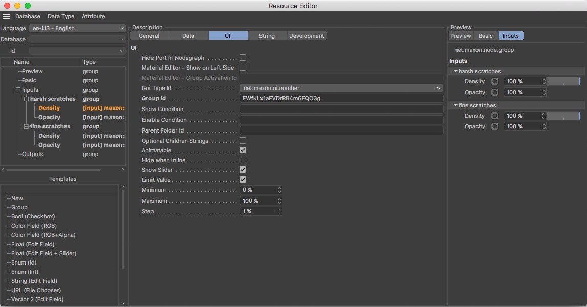 The UI Goup settings primarily affect how the attribute is displayed in the Material Editor and Attribute Manager.
In this menu you will mainly find display options for the respective attribute, its port and its dependency on other groups or attributes.
Hide Port in Node Graph
This option reflects the function of the Hide All Ports command in the Node Editor and hides the attribute’s port in the Node’s display by default. Hidden ports can be unhidden at any time and remain visible in the Attribute Manager at all times.
Material Editor – Show on Left side
This option is primarily designed for the options shown below the material preview in the left column of the Material Editor that are for activating the material channels.
Material Editor – Group Activation ID
Using this option, other groups can be enabled or disabled according to the state of a given option. A material channel in the Material Editor, for example. If the Bump option is enabled, the group with the bump settng will be activated. This option can only be used in conjunction with the Boole type. Use the group’s Identifier as the Group Activation ID.
GUI Type ID
Often, various interface elements are available for the selected Datatype. The following are available:
- net.maxon.ui.bool: A simple option filed that can be enabled or disabled by clicking on it.
- net.maxon.ui.data: The value defined by the Datatype will be output as a setting in addition to the attribute’s Datatype. For a Boole attribute you will then also have a Boole type as well as the value true, for example, as two parameters.
- net.maxon.ui.enum: Makes options available in a drow-down menu. For a Boole attribute, for example, a menu with the options true and false will be made available. As a rule, this GUI type should be used for a more comprehensive menu, which can be created if the Datatypes Int and Interdid are combined for which unique menu elements can be defined via the Enum List.
- net.maxon.ui.linkedport: Hides all input ports and only permits linking with another node.
- net.maxon.ui.nodelink: Makes the individual Datatype elements and the value of the attribute available as inputs. Ports can be linked using the link field.
- net.maxon.ui.variadicport: This is a special type of port that makes it possible to display a port with any number of other ports of this type.
- net.maxon.ui.variadicportplain: Offers the same functionality as net.maxon.ui.variadicport but does not allow the use of the interface with a custom UI.
- net.maxon.ui.color: Makes a color field with sliders for the color components available.
- net.maxon.ui.coloralpha: Makes settings for the alpha component available.
- net.maxon.ui.number: Makes an input field for numeric values available that can also be supplemented by a slider, if desired.
- net.maxon.ui.string: Displays a text entry field that can also hold extended content if the Multi-Line Text Field option is enabled. If Read Only is enabled, the field will be blocked for input and only the text defined by Default Value will be displayed.
Group ID
As soon as an attribute is placed into a group, an Identifier for the group will automatically be placed here. As a rule, this field cannot be modified manually.
Show Condition
Here you can enter the name or Identifier, e.g., for an option. Only if this option is enabled will this attribute also be visible in the user dialog. For complex Datatypes, fixed values can be checked, e.g., with the operation {my value}==2. In this case, the attribute will only be displayed if the setting with the name "my value" assumes the state or value 2. Strings can also be evaluated using this method if these are set in quotations, e.g., {my value}=="Hello". If multiple conditions should be true simultaneously, use the "&&" characters to simulate the logical ,and’ and place the terms to be checked within parenthesis, e.g., ({my value}==2 && {my value}=="Hello").
Enable Condition
This setting worlks exactly like the Activation Condition only that the attribute will not be hidden but only grayed out if the linked option is disabled.
Parent Folder ID
Makes it possible to create groups that can be opened or closed in the Attribute Manager. The group must be assigned a unique ID. All settings that are assigned this ID via the Parent Folder ID function can be opened and closed together.
Enum List
If GUI Type ID is set to net.maxon.ui.enum, enter the Identifier number from the Enum List here as it should appear in the attribute’s menu.
Optional Childresn Strings
If enabled, the strings from the list will not be made available for translation.
Show Slider
If enabled, an additional slider will be displayed next to the input field for a number.
Limit Value
If enabled, an additional option for Minimum and Maximum will be made available. These can, for example, be used for sliders to restrict their value range.
Minimum / Maximum
These settings define the numeric value range for interactive control elements. Note that these values don’t have to be the same as the value restrictions in the Data settings group because they only directly affect a slider’s value range. Smaller or larger values can be applied within the data value range by manually entering the values.
Step
Here you can define the step size with which the attribute value should change when the small arrow next to the input field is clicked or when using the scroll wheel.
Multi-Line Text Field
This option is available for string attributes and makes an enlarged String field available for entering text.
Read Only
This option blocks the string attribute’s String field for input and displays the string’s Default Value grayed out.
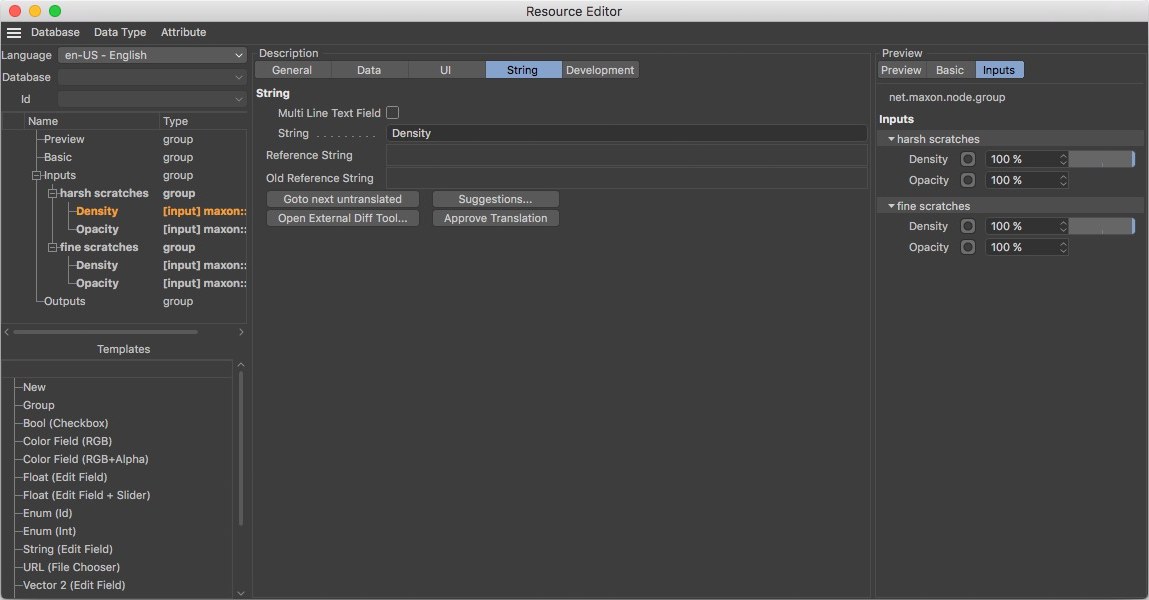
String
 In the attribute settings’ String menu you will mainly find an input field for the name of the attribute. Note that the String field will use the currently selected language that you can define in the top left corner of the Resource Editor. Various translations can be used for different language versions of Cinema 4D.
In this menu you will mainly find the name of the selected property. A group name can be entered for a group. This name will also appear in the Attribute Manager. For attribute properties, the name of a color or numeric value can be defined. Note that these inputs are dependent on the language that was selected. If possible, start with the Engish language en-EN - English and enter the desired name for the group or attribute in the String field. Then switch the language to another intry and translate the string for the setting or group.
Multi-Line Text Field
Makes mult-line inputs possible for Strings and Reference Strings.
String
Here you can enter the name for the selected group or attribute.
Reference String
After switching to another language you will find the group or setting names as a reference as it was entered for English, for example. This makes it easier to translation the terms.
Old Reference String
Here you will find a previously assigned name for the setting that has been replaced by a new string. To use the current string for the selected parameter and language, you have to click on the Approve Translation button. Otherwise, warning icons may be displayed in the properties list that will warn you that the translation has not yet been approved.
Go to Next Untranslated
Jumps to the next string that has not been translated for a laguage other than English. Each modification made to the base language English will result in all languages being marked as not being translated.
Suggestions...
Opens a pop-up window with similar translations.
Open External Diff tool...
Using an external tool to compare long texts can be very helpful. To do so, the environment variable or command line parameter g_externalCompareTool must be set, e.g., g_externalCompareTool="C:\Program Files (x86)\Beyond Compare 4\BCompare.exe,
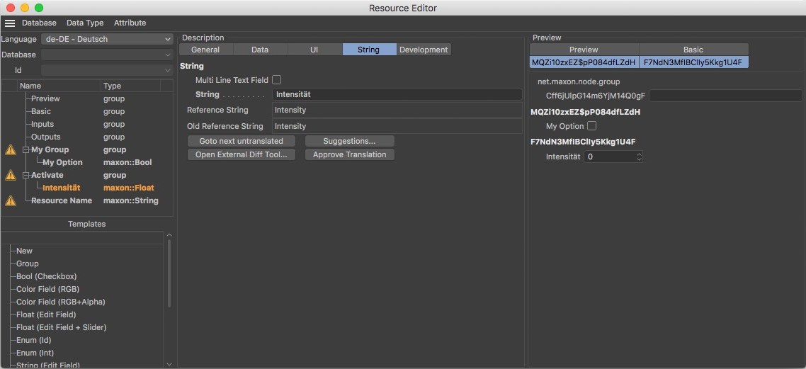 Naming that has not yet been approved will be marked with a warning icon. In these cases, check the String field input in the different languages and approve them accordingly by pressing the Approve Translation button.
Approve Translation
Clicking on this button will confirm the current translation in the selected language. Translations not yet confirmed will be marked with a warning icon in the Resource Editor.
Development
In this menu you will find additional options for attributes that can be helpful when managing multiple versions of a given asset and its resources.
Comment
Here you can, for example, add comments for an attribute to document its function. This information is not made available to normal users of the material.
Ingore in Header File
For developers, C++ header files are exported directly from the tool. If this option is enabled, this attribute will not be exported to C++.
Inherit String
Lets the string be inherited for includes without having to translate it again.
Optional String
If enabled, the translators will not be forced to translate the text.
Resource Editor Menu
In the Resource Editor’s menu you will find items for creating custom data types and for creating, copying and deleting attributes.
Database Menu
Saves all databases to your hard drive.
Data Type Menu
Here you can create a custom data type to which you will have to assign a name. After confirming, the Resource Editor will empty and you can assign the new data type new properties, e.g, from the Templates or Properties fields.
A dialog window will open for the currently selected data type in which you can change its name.
Creates a copy of the selected data type.
Saves the selected data type to a database whose name can be entered in the dialog window that opens.
Removes the active data type from the database.
Attribute Menu
In this menu you can create, copy and delete groups and ports, among other elements. The property types available reflect those of the Resource Editor’s Templates field.
A menu will be made available in which you can call up the desired type of new attribute or group or separator.
Saves the selected attribute to the cache / copies the attribute from the cache to the Resource Editor. The same commands can also be found in the context menu that opens if you right-click on a setting. There, you will also find two additional versions. Copy ID can be used to copy the respective setting’s Identifier. The Paste (Keep IDs) command will paste a copy of the attribute. The Identifier will not be updated. This should remain the exception for special applications since all Identifiers should normally remain unique.
Deletes the selected property and its port from the Node Editor. The same can be done by right-clicking on the property and selecting Delete from the menu that appears. Note that this deletion cannot be undone!