Scene Nodes Introduction
Introduction
Nodes are nothing new for Cinema 4D users. The XPresso System and of course the Material System have been part of Cinema 4D for several versions now. The Nodes System makes individual functions available as Nodes, which are displayed as a graphical element that can be connected with other Nodes to exchange specific information. Connecting multiple Nodes can – just like a programming language – be used to execute calculations or specific functions. For technically-oriented users in particular, this bears the advantage that custom assets can be created for recurring tasks, i.e., custom functions and tools can be created. Nodes also make it possible to access functions that are only partially or not at all accessible via normal commands or objects in Cinema 4D – and this without using programming commands or having to know programming code!
Now this concept can be used to create geometry in Cinema 4D. You can, for example, create custom Deformers or entirely new distribution functions for clones. This is what can be done with the new Node Editor, which can be accessed via the main Window menu in Cinema 4D.
New nodes can be selected and added there via the corresponding button at the top of the editor.
The "Scene Root” node is already present and represents the connection point between the objects generated via nodes and the open project. The geometries connected here appear not only in the viewports, but also in a "Scene Manager", the counterpart to the old "Object Manager", where node objects can be grouped hierarchically, renamed or their visibility controlled, for example, as usual.
.
Generate or create geometry
The Scene Node tools also offer the common primitives that can be generated. An example of this can be seen here:
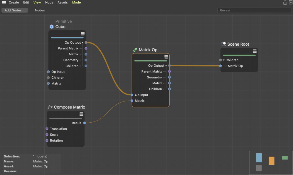
A Primitive Node is used to generate a cube. This Node’s output can be connected directly with the Scene Root but we add our own matrix first, to be able to position, rotate and scale the cube to our likings. The Matrix Op Node’s output contains the position information for the cube and can be sent to the scene. The cube will then appear at the defined position with the respective rotation in the Viewport. Alternatively, the "Primitive" node itself offers matrix settings for placement, rotation and scaling.
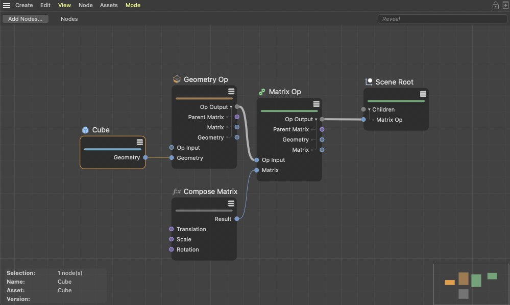
Since more and more roads lead to Rome we you can also get more into detail because the cube shape can also be called up as a Geometry Node. Contrary to the Geometry Op Node, this Node does not offer the possibility of switching to other primitives and only offers a single Geometry output, which basically only contains the information pertaining to points, edges and polygons. Other typical object information such as a freely definable display color or the option of being hidden in the Viewport are not available here. This information can, however, be added via a Geometry Op Node in order to make an object out of geometry:
The greatest amount of control over geometry is offered when you create it yourself using points and edges. You can, for example, use your own point order or execute mathematical calculations to create abstract shapes.
For this, Arrays must be filled with values, which can be done using a Build or Index Array from String Node. You can imagine Arrays as a list with different consecutively numbered values. This should already be familiar to you from the Structure Manager where a polygon object’s points and polygons can be displayed as such in a list.
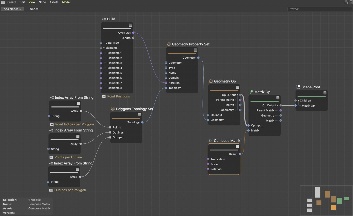
The Polygons Topology Set Node can be used to set the points’ numbers that belong to a given polygon. Since this series of numbers does not contain information regarding, for example, if polygons should be created as triangles or quads, you will have to add an Array that contains the number of points for each polygon that has continuous edges. This information will be named Border in the Node. Finally, the information regarding the number of borders that the polygon should have is missing. Normally, this will only be one border but N-Gons can, of course, also be generated that have a hole. In this case, a border for the outer shape of the N-Gon and a border for the opening will be defined. This information will be named Groups in the Node. Together, the information about the point indices, borders and groups is referred to as Topology and can be combined to create geometry via the Geometry Property Set Node. To do so, the position of all points must be set. For this, an Array will again be required that is defined via a Build Node as seen in the image below.
Splines can also be drawn in a similar fashion.
Modeling Funcitons
Modeling functions
Common modeling functions such as Extrude, Inset and Bevel are also available and can be restricted to specific elements on a geometry via a selection.
Here, Arrays can also help by passing the indices of selected points or polygons to the modelling commands. A special type of Array is needed to select edges because edges are only defined by their end points.
However, the Index Array from Text Node can be used in both cases to define the indices of the points or polygons. An Active Selection Node can be used to output a saved selection (via Set Selection Node) or to directly select input indices on the geometry.
Subsequently added modelling Nodes will then automatically be restricted to this active selection. Alternatively, indices can be passed directly to the modelling Nodes. In the following image you can see all commonly used variations for handling selections.
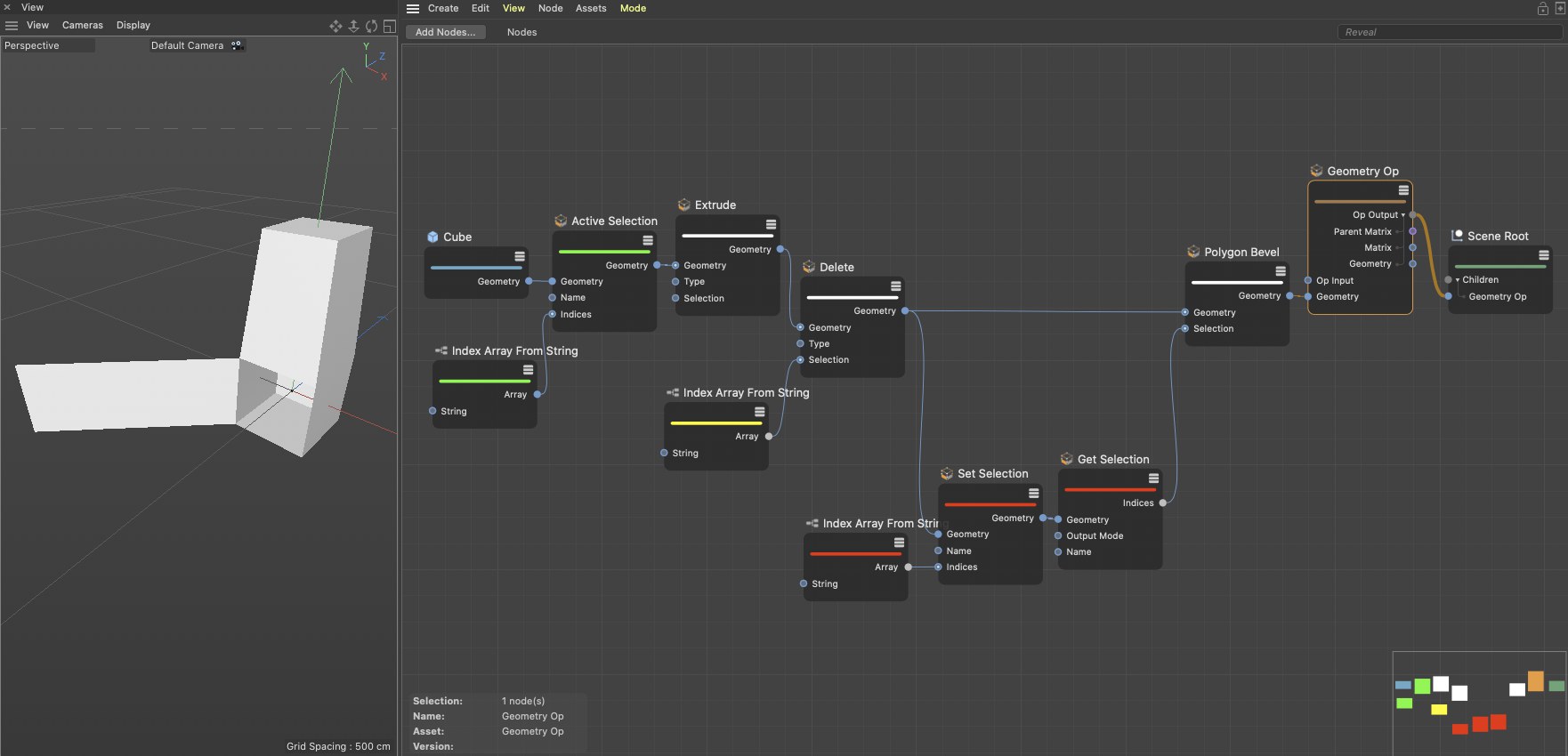
The green marked Nodes uses a list of point indices to create an active edge selection, which will then be extruded.
The yellow marked Node contains the index of a polygon that is subsequently deleted using a Remove Node. The red Nodes also use a list of indices that is saved under a unique name via a Set Selection Node. The following Get Selection Node reads the selection with that name and passes this to a Polygon Bevel Node to extrude the caps surface in a pyramidal shape.
Creating and managing multiple objects
If several node objects are created, they can also be connected to the "Scene Root" node. This has a variable number of inputs. To do this, simply use the "Add input" and "Remove input" buttons on the node. Otherwise, nodes such as "Primitive" or "Null" also offer a variable number of "Children" inputs themselves, in order to be able to create hierarchical object groups.
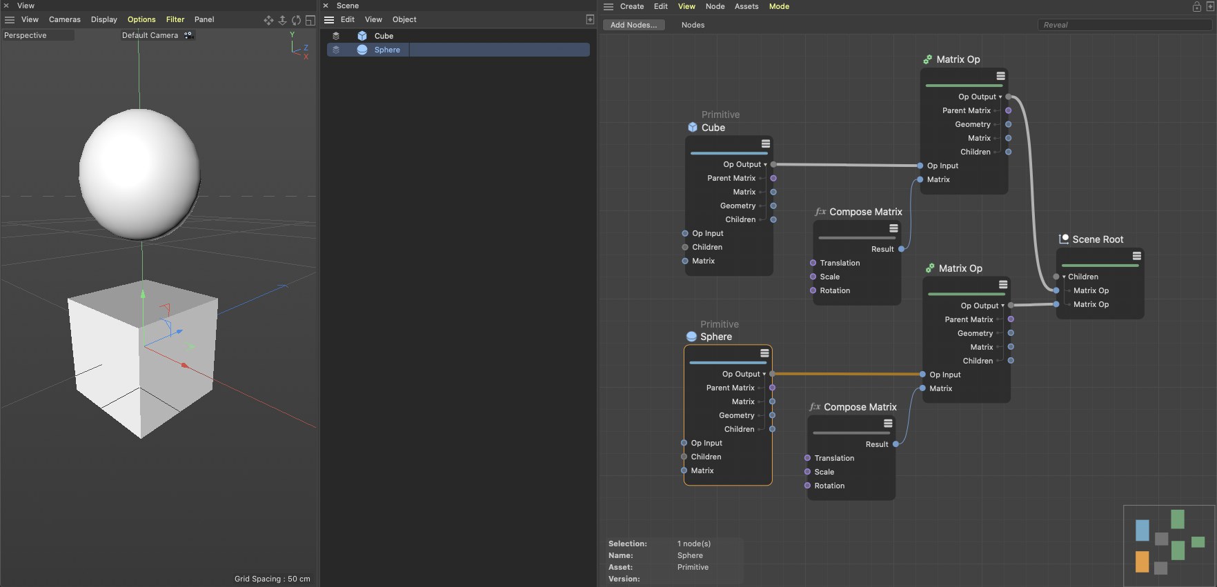
This way, object hierarchies can also be created.
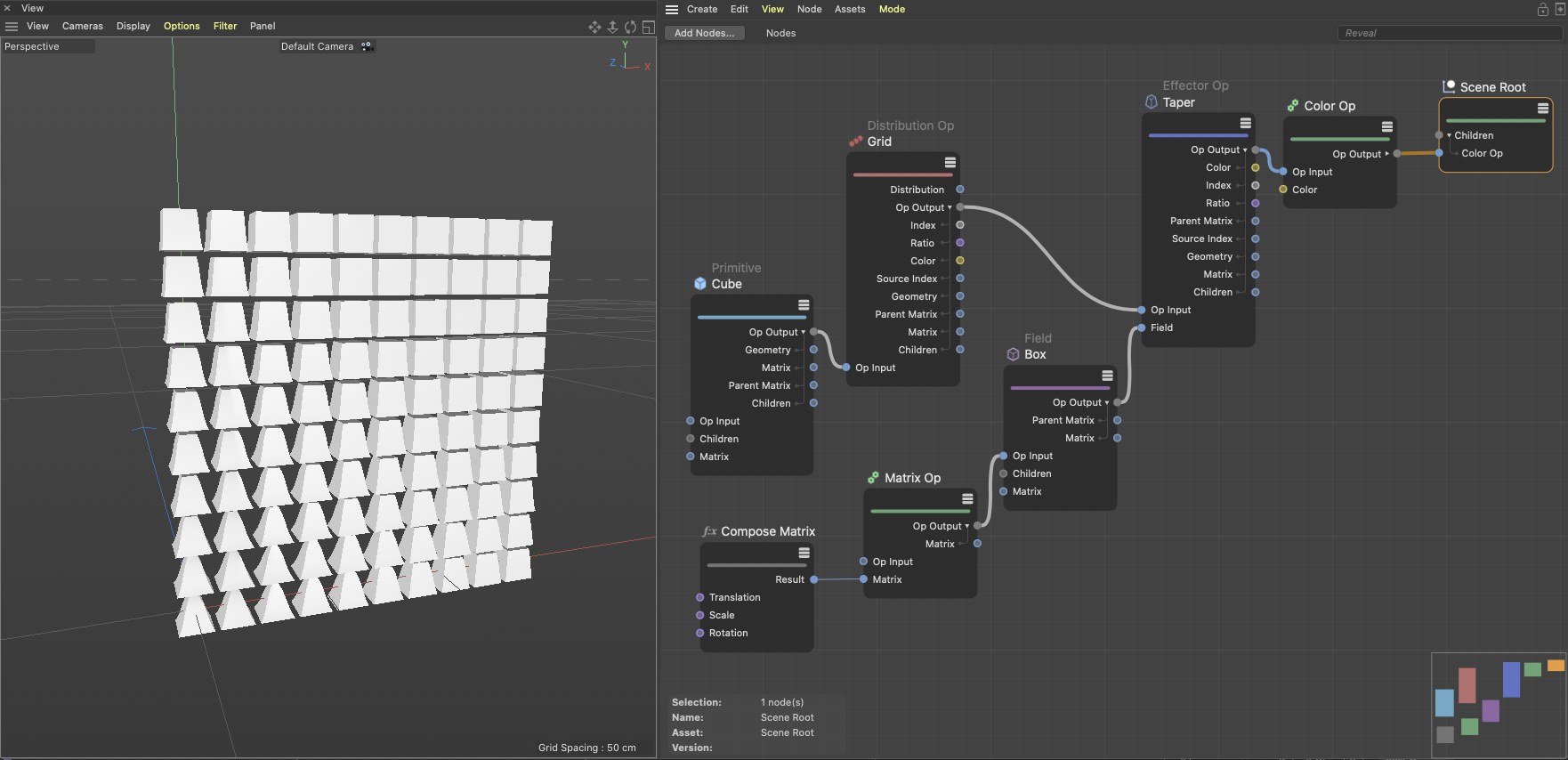
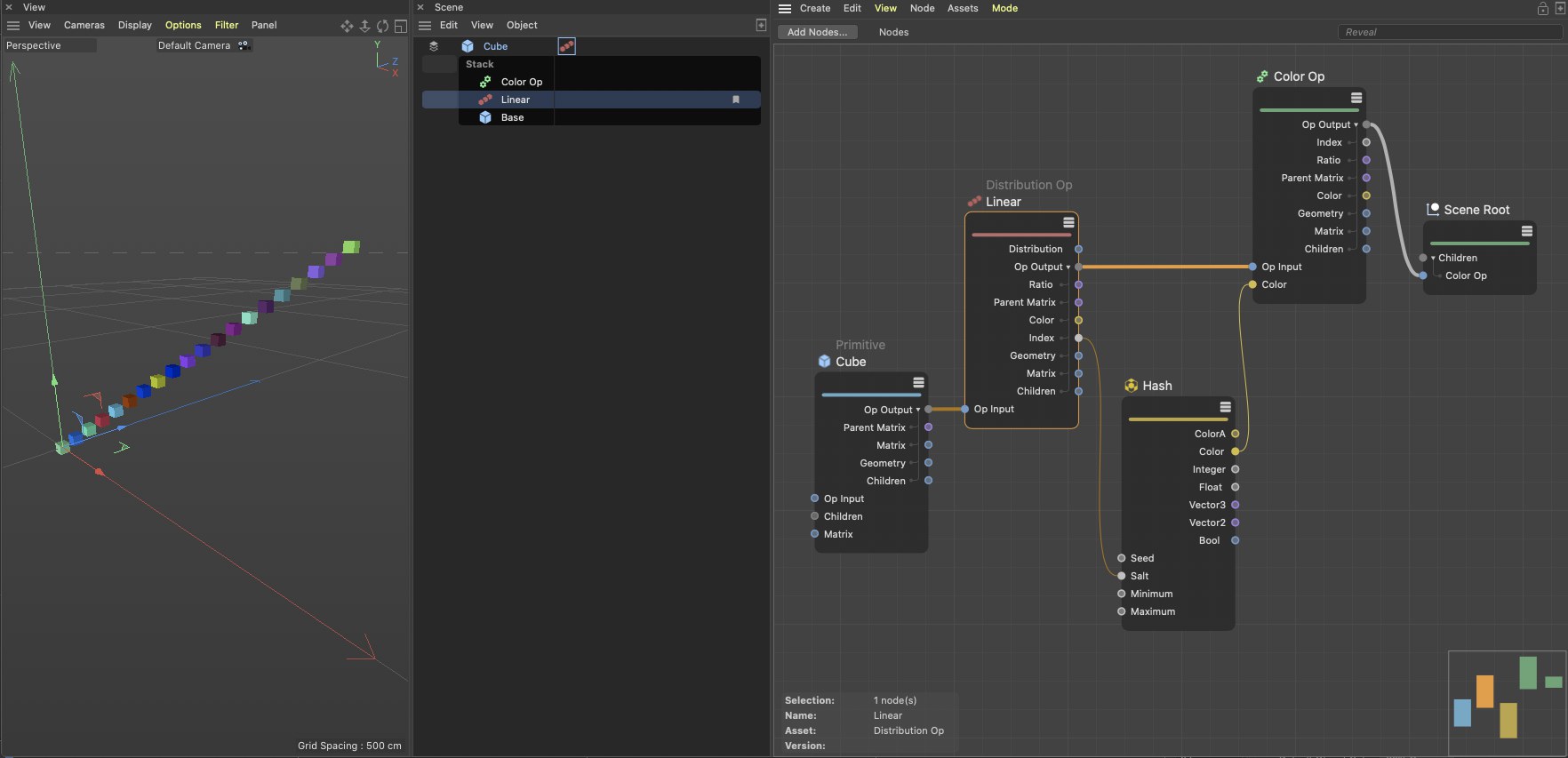
If you want to duplicate objects you can, for example, use a Distribution Op Node, which can be used similarly to the MoGraph Cloner object. A linked object will be cloned at the defined positions and can then be sent directly into the scene. The Color Op Node can be used to color these clones individually. In the example image below, a Hash Node was used to randomly generate colors.
If you need even more control you can arrange the geometry for the calculated positions yourself using the Distribution Op Node to output matrices that can, for example, be connected to a Matrix Op Node with objects :
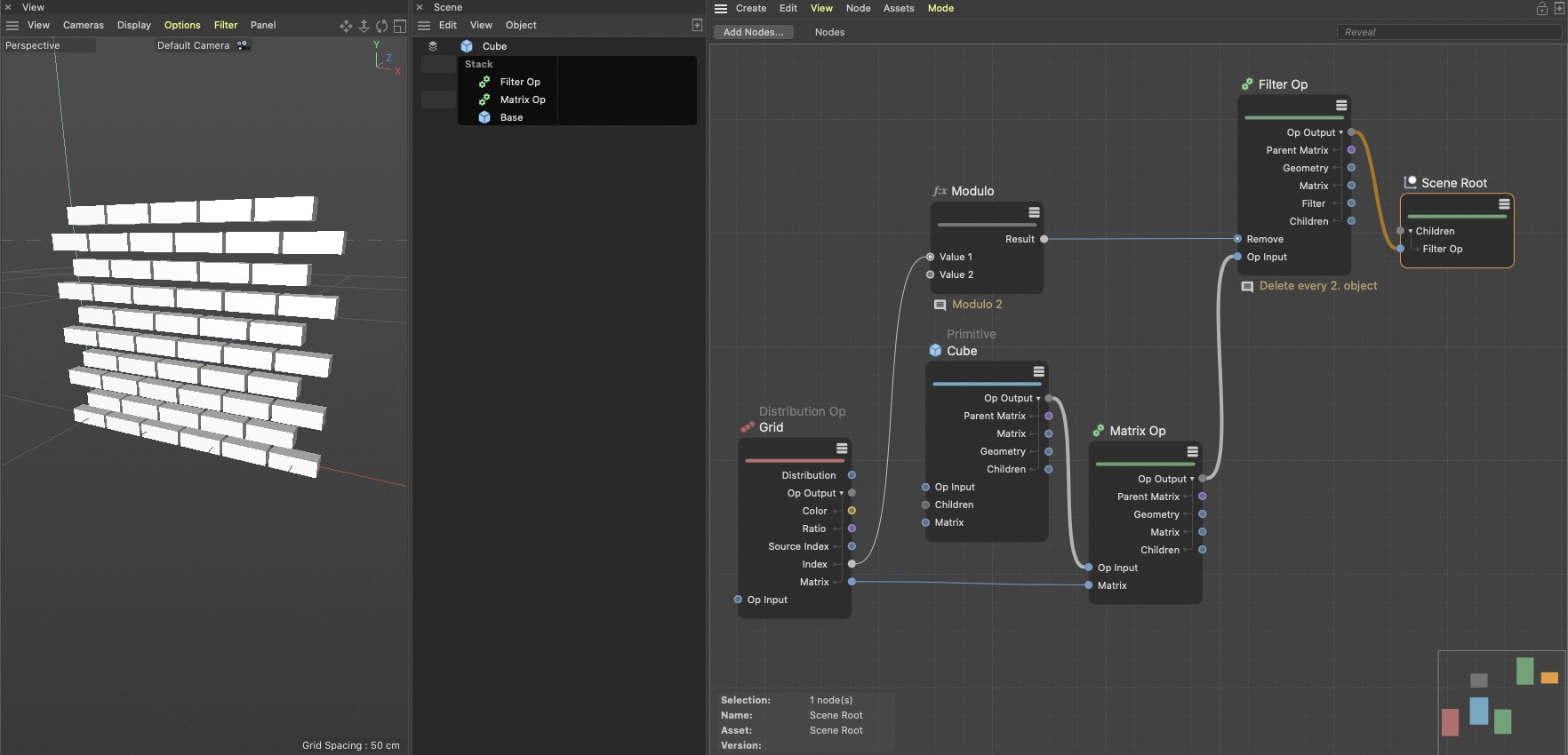
In this example you also see how objects from a distribution can be deleted. Here, a mathematical Modulo with a value of 2 for the clones’ index numbers is used to only deliver results between 0 and 1. These values can be interpreted as Boole values via a Filter Op Node, which will result in every other object automatically being removed. A typical beehive or brick pattern will result.
Of course the position and shape of the copies that are created can be modified. Various Effectors are available with which this can be done. The Effector Op Node offers a wide range of common deformations such as Bulge, Taper, Twist and Bend. You can also create custom algorithms via an Effector Group Node. Separate fields, which can be selected via a Field Op Node, can be used to spatially restrict the effect of the deformation: