Asset Capsules
The number and functionality of Scene Nodes has been growing rapidly with each release. Nevertheless, there are still objects and functions that are not currently available as Nodes.
On the other hand, functions and generators can already be configured with Nodes that do not exist in the classic Cinema 4D environment. Therefore, what if we could combine the strengths of both systems?
This actually works if you follow some rules while creating Node assets.
Using Node based assets in the Object Manager
You can already find some assets that are suitable for direct use in the classic Cinema 4D environment in the Asset Browser. For example, take a look at the "Geometry Generators" section and find the "Atom Array" there. This feature is similar to the classic Atom Array generator, but offers additional options, e.g. to assign materials directly to the spheres and cylinders or to edit the length of the cylinder elements.
So try dragging this asset from the Asset Browser directly into the Object Manager. As if by magic, an Atom Array object will now appear there and the Attribute Manager will also show the settings of this Node asset. If you now group any polygon object under the Atom Array, it will start working. So you don't notice at any time that you are dealing with a function based on Nodes only.
Try this again right away, for example by dragging the “Mesh Primitive” Asset or the “Spline Primitive” Asset from the Asset Browser into the Object Manager. These Node functions are now also displayed there like classic objects and can be combined with classic objects, for example. You can certainly see now what possibilities this opens up. You can construct your very own objects and generators with Nodes and combine them with classic Cinema 4D objects directly in the Object Manager.
The user of such assets doesn’t need to know anything about Nodes for this and can operate all functions via the familiar managers.
Create your own asset capsules
If you experiment a bit with the Asset Browser and also try to drag other Node based assets into the Object Manager, you will notice that this doesn’t work with all assets.
There are certain rules that must be followed when building such assets, and also not all functions are currently directly compatible with the Object Manager and classic Cinema 4D functions.
Therefore, it is not possible to simply generate an asset from any group of Nodes and expect it to work in the Object Manager. Special asset capsules have to be created.
An asset capsule is basically identical to a normal asset and is also created in the same way. However, it contains certain elements that can currently be evaluated by the Object Manager and the classic Cinema 4D environment.
These include:
-
Mesh Primitive Group: Use this group as an asset when you want to create parametric objects.
-
Object Group: Create an asset from this group if you want to create a generator that can handle child objects, for example, similar to the Atom Array asset presented earlier.
-
Selection Modifier Group: If you convert this group as an asset, you can create your own selection functions.
-
Geometry Modifier Group: An asset from this group can be used like a modeling command in the classic Cinema 4D environment. This allows the use of modeling stacks in the Object Manager, just like the Scene Manager offers.
The use of assets with distributions, effectors or fields is currently not yet possible.
However, the use of asset capsules also has disadvantages, or is currently not yet suitable for all scenarios. For example, the use of XPresso for linking parameters and for mathematical calculations between user data and object parameters still has advantages. The use of asset capsules in the Object Manager and in combination with classic objects is only possible through internal conversion, which costs computing time. Complex assets can therefore not take advantage of the speed advantage of Nodes, which can otherwise be observed when working natively in the Node Editor. Therefore, the use of asset capsules for the creation of parametric objects and for editing splines and polygon objects is particularly appealing.
Creating a modeling capsule
To generate modeling functions as a capsule, the "Geometry Modifier Group" Node must be used as a base. This group provides an input and output for geometry.
 Create your own modeling function with a Geometry Modifier Group.
For testing the setup, other Nodes outside the group can be connected here, but for converting to an asset, only the group itself will be needed later.
If you want to provide additional options via the Attribute Manager, there are two ways to do this:
-
You drag a connection wire from an existing input of a Node in the group to the left input area of the group. When you release the mouse button, a context menu appears in which you can select "Add New Input". This automatically gives the group an additional input that matches the port you dragged. The name, the default value, unit settings and the UI element of the parameter are taken over.
-
The second option is available via the "Resource Editor". To do this, right-click in the open group or on the group Node itsels and select "Edit Resource" from the context menu. The Resource Editor opens, where you can create your own ports, select data types and edit names. This option is also useful if you want to make several parameters available as inputs and edit their settings in an individual layout. The Resource Editor also already offers typical data types and control elements in the lower left column as presets, which can be dragged directly into the list of inputs and outputs above. The controls, default values and names of selected ports can then be edited in the middle column of the editor, along with many other settings.
Let's run through this using a simple modeling function as an example. These steps can then be applied to all other assets and asset capsules.
To do this, create a "Geometry Modifier Group" and open it by clicking on its folder icon in the header. Now decide on a simple modeling command, such as the "Chamfer" Node, and drag it from the Asset Browser into the group. This Node offers two modes. Here we opt for the "Type" setting "Edges" to round off edges.
The user should later be able to set the radius of the rounding ("Size" parameter) and the subdivision of the rounding ("Subdivision" parameter) himself. Therefore, we now have to make these two settings available at the input side of the group. You therefore add inputs at the "Chamfer" Node for these parameters in a first step by right-clicking on the Node and then navigating to the desired parameters via the "Add Input" menu item. As explained in the paragraph above, you then drag and drop these new input ports to the left side of the group.
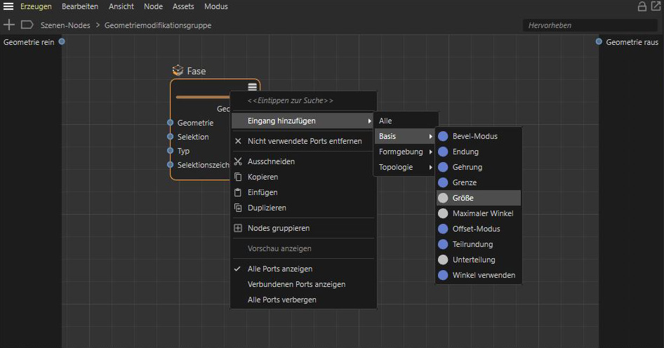 Add new inputs at the Chamfer Node for parameters that you like to make available to the user in the Attribute Manager.
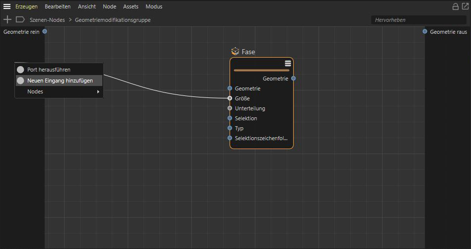 By dragging an input port from a Node to the left side of the group, you can add this parameter as an input at the group by choosing "Add New Input" from the context menu.
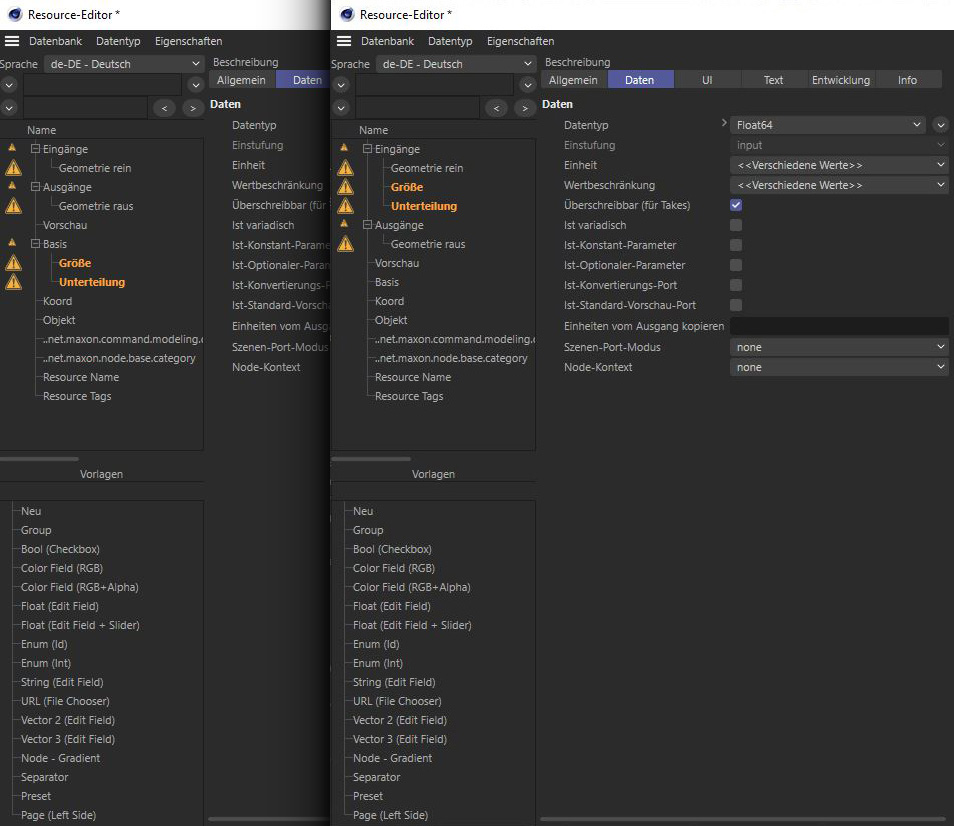
How about giving the user other setting options as well, such as an input option for the name of a saved edge selection, to be able to restrict the modeling command to selected edges only? In addition, an invert function for the specified selection could also be helpful to round all edges except those that are in the specified selection. To do this, we would need a string input field and a boolean option as inputs. We create these via the Resource Editor.
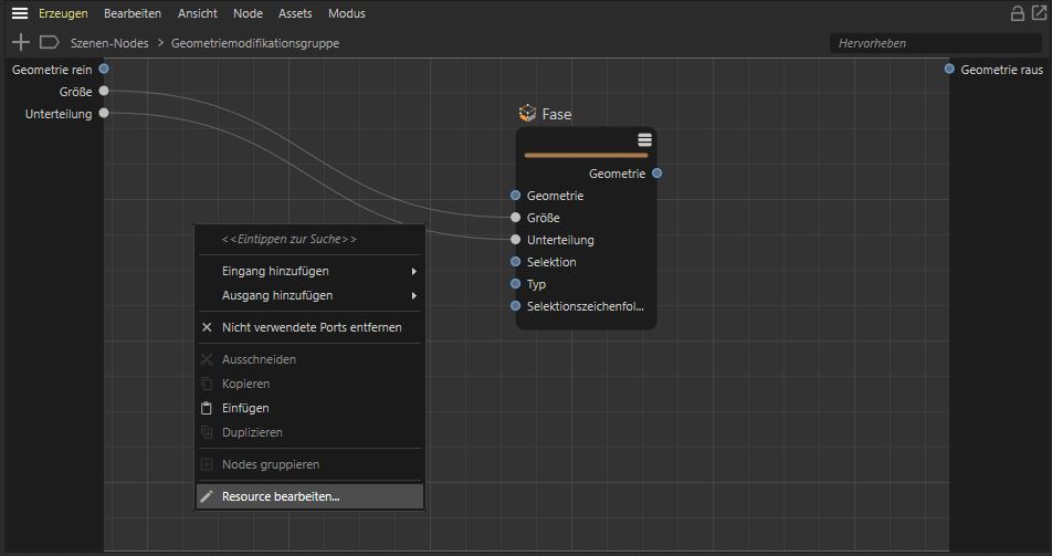 Open the Ressource Editor to add individual inputs to groups and to edit the user interface for assets.
To do this, right-click in the empty area of the opened group and select "Edit Resource" from the context menu. In the upper left list you can see all parameters of the group. For us, the entries under the "Inputs" group are interesting. As a rule, the inputs you have created should appear here. However, the two parameters linked by the "Chamfer" Node appear under the "Basic" group. This also works, but then it may lead to a splitting of the parameters into groups when they are displayed in the Attribute Manager. We therefore simply drag and drop the two entries for "Size" and "Subdivision" under the "Inputs" group. This way, inputs can also be reordered if you want to present the parameters in a different order in the Attribute Manager.
 The order and grouping of existing ports can be edited in the list view of the Ressource Editor.
The Resource Editor also offers a preview for this on its right side. However, this only works if the group for which the resource is being edited is also functional. Currently, for example, the "Geometry Out" output of the group is not yet connected. We will therefore do this directly.
Close the Resource Editor, drag a connection from the "Geometry" output of the "Chamfer" Node to the "Geometry Out" port of the group, and then reopen the Resource Editor for the group. Now you will get a preview of the interface on the right side as it is displayed in the Attribute Manager. This includes the preview areas for shaders and materials, as well as the basic settings section. However, for us in this case, only the lower part with the "Inputs" is interesting, where we can now see our two parameters.
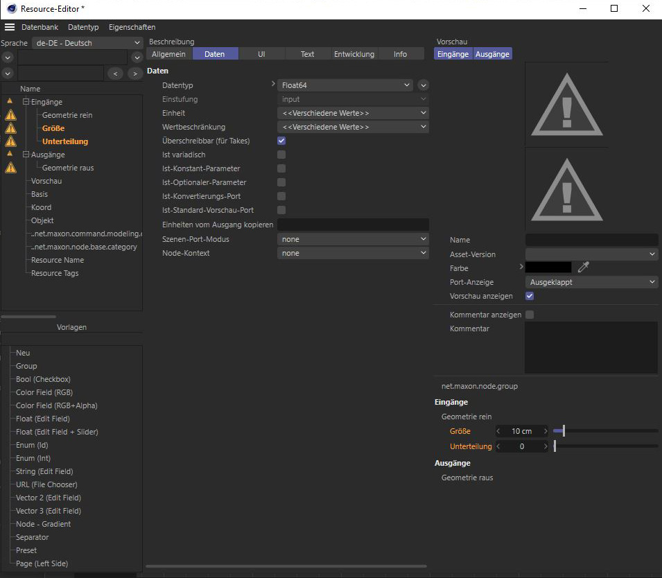 The right side of the Ressource Editor offers a preview of all input parameters. You can check the data type, units and UI elements used for your inputs there.
Next, we add a string input field as an input so that the user can later enter the name of a saved edge selection here, if desired. To do this, you'll find "String (Edit Field)" in the list at the bottom left, and simply drag it to the desired location under "Inputs". We also add an option to optionally invert the selection with a checkbox. This element can also be found in the list at the bottom left under "Bool (Checkbox)".
The two new inputs are given cryptic names in the ports list by default, which we should edit. To do this, click on the corresponding entry in the "Inputs" group and select the tab for “String” in the middle column of the Resource Editor. Enter the desired name here, which should then also be visible in the Attribute Manager next to the string input. Proceed accordingly with the Boolean input that is to be used for the invert function.
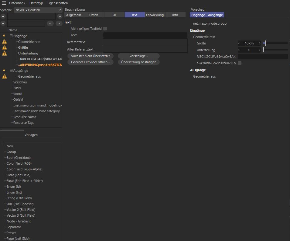 New parameters added in the Ressource Editor get cryptic names by default. Use the String setting to enter individual names for your inputs.
Settings for limiting possible inputs, as well as default values or units, can be found under the "Data" tab of the middle column in the Resource Editor. Here you could, for example, use the input option for "Default Value" to store values for inputs that the user will then find directly when using the asset for the first time. This is not necessary with our parameters. Once all inputs have been created, the Resource Editor can be closed. The new inputs are now created at the group.
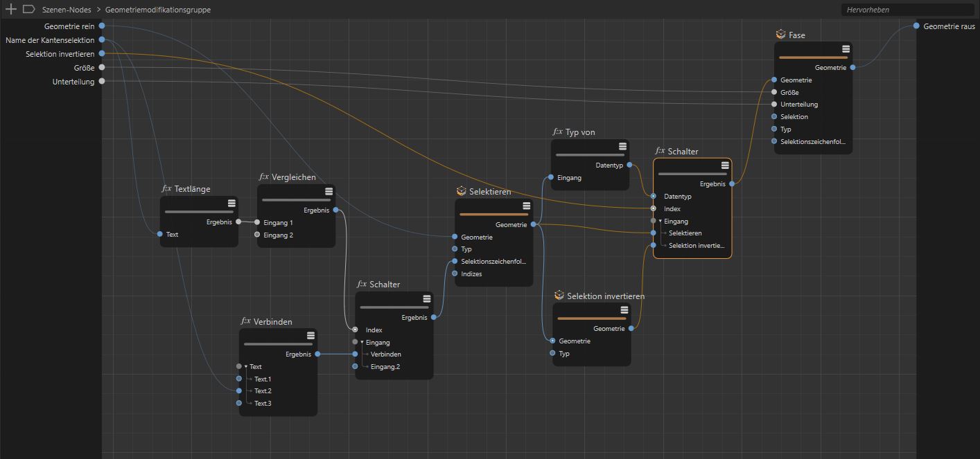
Since stored selections can be read directly via a "Selection String", but this expects the name of the selection in quotes, we must now supplement the name input with quotes. This can be done very easily with a "Concatenate” Node. In addition, a “String Length” Node in conjunction with a "Compare" Node can be used to check whether an input for the selection name has been made at all. If not, the default string default can be output via a “Switch” Node. This leads to the fact that a “Select” Node simply selects everything or falls back to the currently active selection. An "Invert Selection" Node can then invert the result.
In order to be able to choose between normal and inverted selection, we add a "Switch" Node at the end that uses the "Geometry" data type. Drag any "Geometry" output to the "Switch" Node and link it to the "Data Type" input. This way the signal of the invert checkbox can be used to switch the geometry. The result consists of a geometry that can be routed directly to the "Chamfer" Node. Thus the group is already functional.
 New parameters added in the Ressource Editor get cryptic names by default. Use the String setting to enter individual names for your inputs.
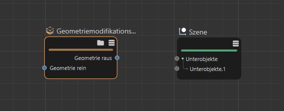
A quick test will verify this. We use a cube geometry for this, on which we store an edge selection with "Store Selection" e.g. with the "Selection String" 0-1 under any name.
The same name is then entered at the "Geometry Modifier Group" and its result is connected to the "Scene Root" via a "Geometry Op" Node. If everything works as expected, the "Geometry Modifier Group" can now be converted to an asset. To do this, select the group and choose "Convert To Asset..." from the “Assets” menu in the Node Editor. Once packaged as an asset, the contents of the group can no longer be viewed or edited. However, you can also convert an asset - provided it has not been encrypted - back to a group. This is also possible via the "Assets" menu of the Node Editor. In addition, after right-clicking on an asset in the Asset Browser, "Edit..." can also be called to display the contents of an unprotected asset in a new Node Editor.
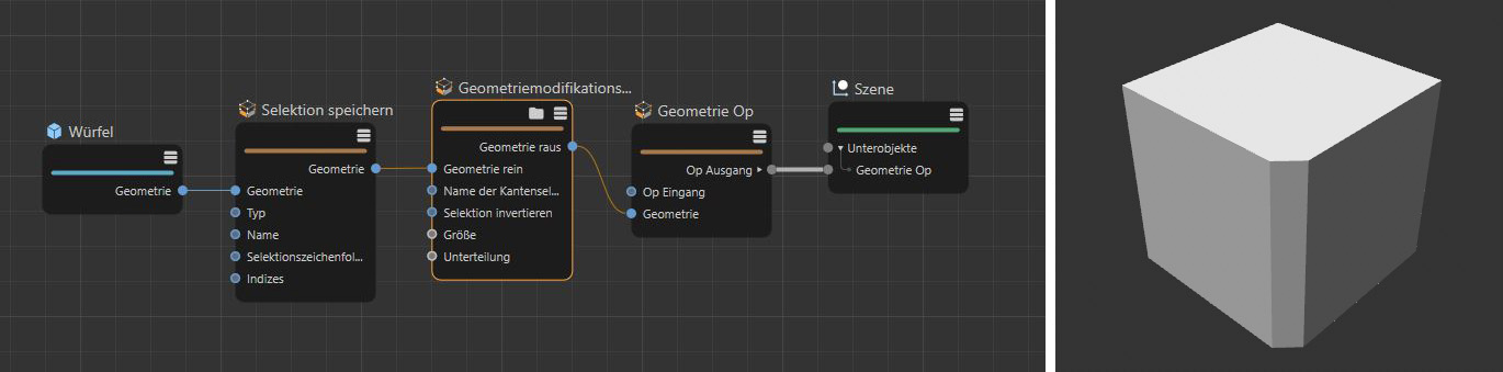 Before we create an asset from our group, we test the functionalty in the Node Editor. Using the Selection String 0-1 with a cube will select one of its vertical edges, as you can see on the right side of the image.
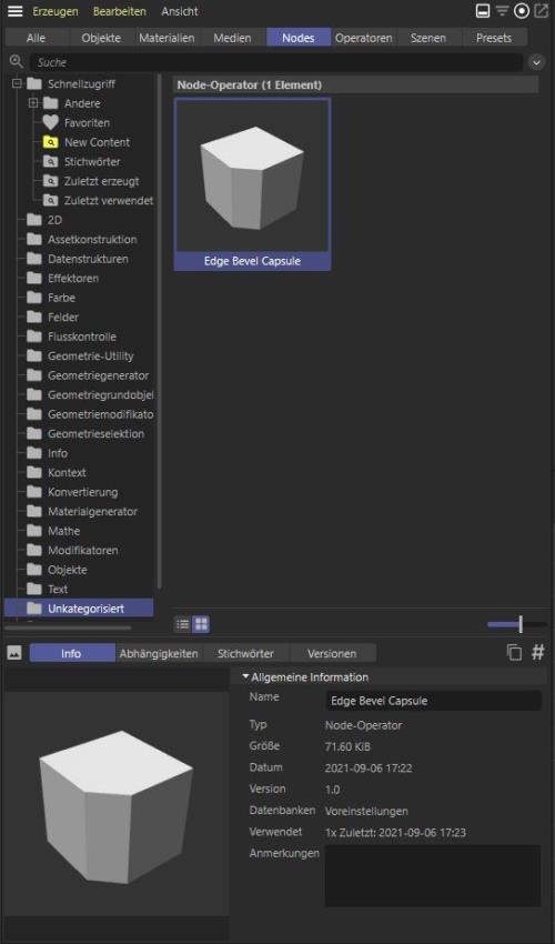 Assets can be given individual keywords and preview images in the Asset Browser.
When converting the group to an asset, a small dialog appears in which you enter the name under which the asset should later be found and also determine the directory within the Asset Browser. The name of the asset will also be used for the capsule object in the Object Manager. Therefore, choose something meaningful here that describes the function. If you plan to create multiple assets or share them with other users on your network, it may make sense to create your own database directory by selecting "Database > Create New Database...". Otherwise, the "Preferences" database is used by default.
Assets can also be exported directly from the Asset Browser for easy sharing. To do this, right-click on the asset in the Asset Browser and select "Export Latest Version...".
In the same menu you will also find an option to export an encrypted version of the asset. This can then no longer be converted to a group. This would be useful, for example, if you want to create assets for sale, or to prevent modification by third parties. This function is not suitable for archiving, because you can then no longer access the contents of the asset!
The new asset can then be found in the Asset Browser under "Uncategorized". In the "Details" section of the Asset Browser, you can right-click on the asset's icon to load an individual preview image or paste it from the clipboard. In addition, keywords can be assigned here, e.g. to simplify the subsequent search for this asset.
Once saved as an asset capsule, there is nothing to stop it being used in the Object Manager. To do this, drag the asset directly from the Asset Browser into the Object Manager. Since this is an asset that uses modeling functions, it must be placed under a geometry. The inputs of the former group can be found in the Attribute Manager as usual.
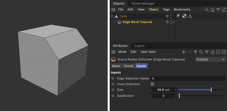 Once converted to an asset, the new modeling function can be used directly in the Object Manager and controled by our settings in the Attribute Manager.

Creating a selection tool as a capsule
The principle described in detail above can also be transferred to other capsule types, such as the "Selection Modifier Group", with which we can make selections of points, edges or polygons. It can also be used to save selections under a name, which can be transferred to classic objects in the Object Manager. To demonstrate this, we will use the "Select Facing" function and add the option to invert and save the selection.
To do this, we first create a "Selection Modifier Group" in a new scene and open it by clicking on its folder icon in the header. Inputs and outputs for the geometry are already present, so we can directly add a "Select Facing" Node and link it to the geometry input of the group. To make the settings for "Orientation", "Tolerance" and the "And Opposite" option also available in the Object Manager, drag these ports to the group's input area and have new inputs created there. We already covered this in detail when discussing the "Geometry Modifier Group" in the previous section. There we also discussed how to use the Ressource Editor to configure custom inputs and set default values and interface elements for the parameters, for example. If necessary, read there again to add a string input for the name of a selection and a checkbox to invert the selection.
As in the example before, we use an" Invert Selection" Node to invert the selection and a "Switch" Node to switch between the normal and the inverted selection, based on the state of the checkbox at the input of the group.
With a "Store Selection" Node, the selection at the geometry can then be stored under a name. To catch the case that the user makes no input in the name field, we first use the "String Length" check and use its result as a signal at another "Switch" Node. If no name input was found, the string length calculation returns 0 as the result, which leads to the output of the first input at the “Switch” Node, which must use the string data type. So here you can enter a default name like Sel, which should be used to store the selection in case of a missing input. At the second input of the "Switch" Node you connect the input of the name. If the "Cycle Indexes" option is disabled on the "Switch" Node, this name will then always be used unless the name field is empty. The result of the "Switch" Node can then be connected to the "Name" input of the "Store Selection" Node.
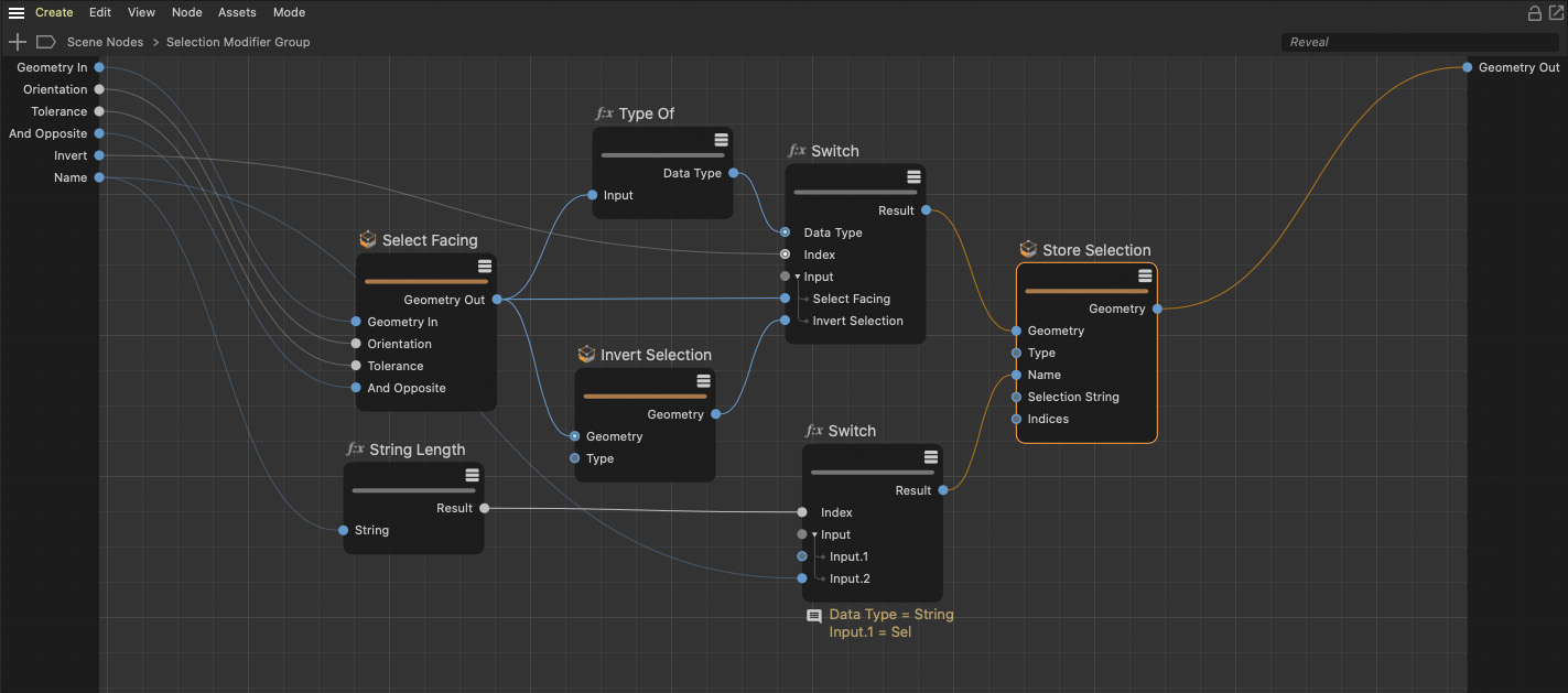 With this setup we offer the user to enter a name to store the result of the Select Facing Node with an option to invert the result..
Since "Select Facing" can only select polygons, "Invert Selection" and "Store Selection" must also be in polygon mode. The result of the "Store Selection" Node is then finally connected to the geometry output of the group. If you now go back out of the group in the navigation bar of the Node Editor by clicking "Scene Nodes" there, we are already done. As demonstrated earlier, let's save the group as an asset under any name and then drag that asset from the Asset Browser directly into the Object Manager. To try it out, let's use the scene from the last example by dragging the new selection asset under the cube and below the modeling asset.
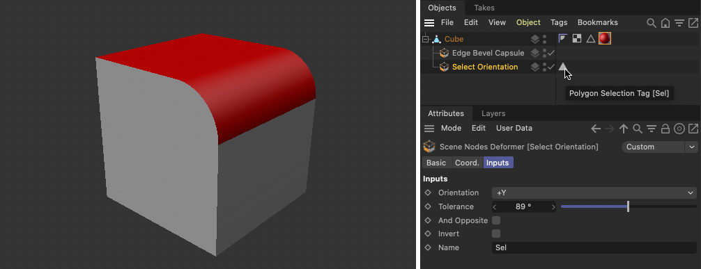 Using the new selection capsule in the Object Manager allows us to create and store a polygon selection and use it for instance to apply a material..
As you can see, the typical tag for a polygon selection appears directly behind the selection capsule in the Object Manager. The name of this selection can be used directly for a material or, for example, it can be used to constrain deformations, as shown in the image below. There the selection on the tube object is not only used for a material, but with a "Restriction" tag also for a formula deformation with the formula Y(x,y,z,t) = 2*y, which shifts the cap surfaces outwards. In this way, the segments along the height remain restricted to the center of the parametric tube.
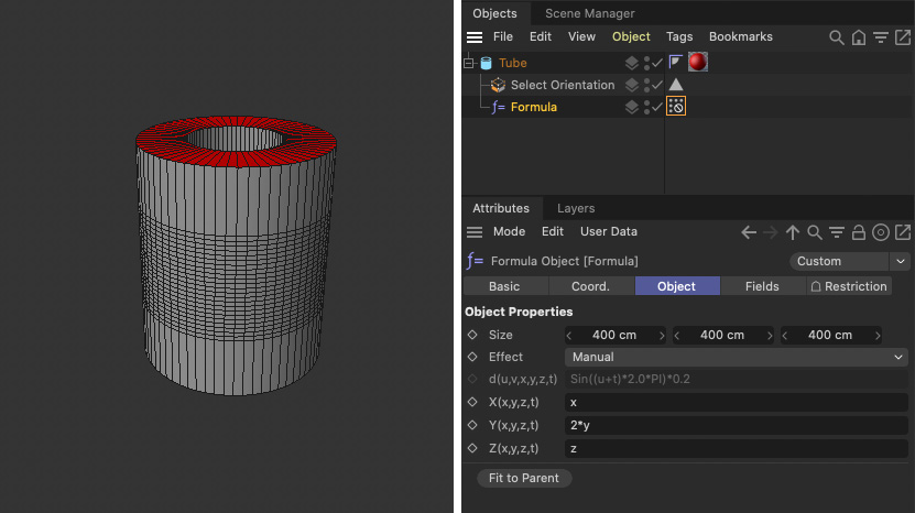 The stored selections created by the selection capsule can also be used in combination with classic deformations as in this example.
Create your own parametric primitive
Another exciting feature is the ability to create your very own parametric objects for Cinema 4D. This works for splines as well as for polygon objects. The "Mesh Primitive Group" serves as the basis for this.
It offers no geometry input, so you must therefore either fall back on Nodes that already provide basic shapes, for example, or create a topology yourself using "Geometry Property Set" from point coordinates and a connection sequence for creating the edges and polygons. In our example we use a ready-made cube and let the "Chamfer" command double an edge on it. This works by having the "Chamfer" Node use an Offset of 0. The cube will then look the same as before, but will now have doubled points along the selected edge.
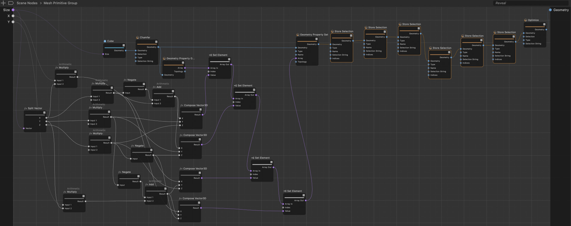 This example is using a simple cube geometry as a basis and the applies a Chamfer command to one of its edges. The new points at that rounded edge are then moved by the user input variables X and Y. The modified point positions are updated in the array of point coordinates and the written back by using a Geometry Property Set Node. The right side of the setup shows just the creation of selections for polygons and edges, before an Optimize command cleans any points that share the same position.
The array with all point positions is read out via "Geometry Property Get". Mathematical calculations can then be used to move these points, for example, and "Set Element" Nodes can be used to write the changed positions back into the original point array. A "Geometry Property Set" Node then writes this array back to the geometry of the former cube.
To provide added value to the user, we use additional "Store Selection" Nodes to make it easier to add materials to the faces of the beveled cube later. Also the two edges at the bevel are stored in two new edge selections. At the end, you can also add an "Optimize" Node, which ensures that the points lying on top of each other are optimized when the maximum values for the edge offsets are used. In the end the resulting geometry is connected to the geometry output of the group.
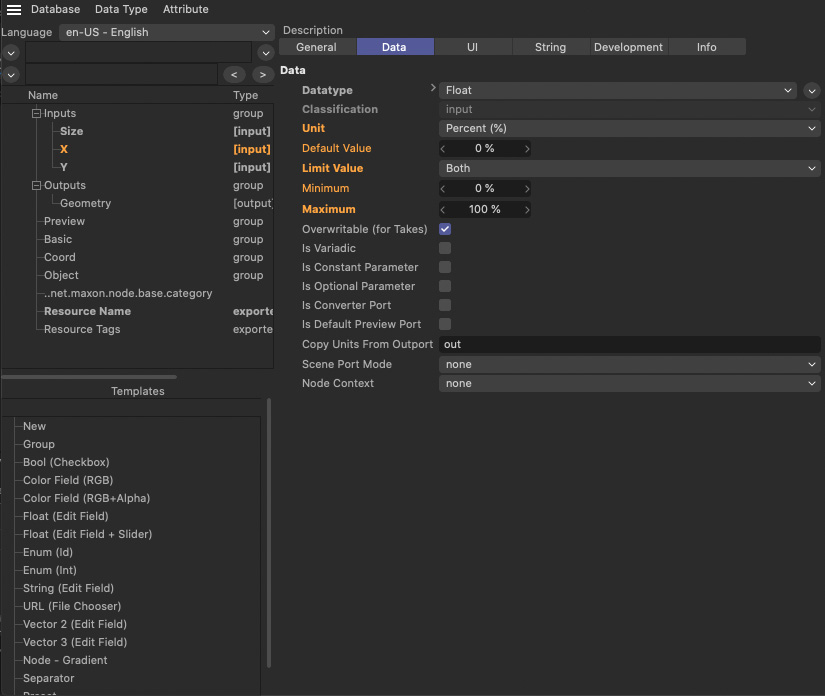 The two percentage values offered to move the points at the chamfered cube edge are added via the Ressource Editor. The Data section of the settings there allow us to specify the Data Type as well as to limit these values to a range between 0% and 100%.
In our example, the "Size" vector of the cube has been created as an input, along with two percentage values that can be used to move the two edges at the rounded corner individually. You create these inputs using the Resource Editor, where you select the default for "Float (Edit Field & Slider)" to create a number field with a slider attached. Then in the "Data" tab, select the "Unit" Percent and use "Limit Value" Both with 0% as the minimum and 100% as the maximum so that the user can only set values in this range of values.
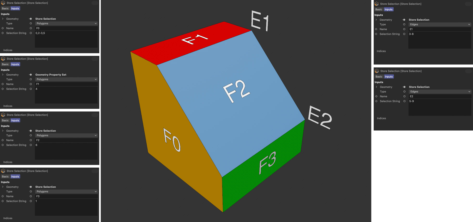 The images shows all settings of the Store Selection Nodes and where these selections can be found at the resulting geometry.
If the group is converted as an asset and saved in the Asset Browser, it can be dragged from there directly into the Object Manager to create a parametric object. The created selections are invisible there, but can be used e.g. by Material Tags (via the selection names F0, F1, F2 and F3). The example in the following image also shows that grouped bevel deformers can also be restricted to the edges on the side of the former cube, using the selection name E1 and E2. Further examples of such asset capsule types can be found in the "Geometry Generator" section, such as the "Brick Wall", the "Stairs" or the "Tree" asset.
Creating a parametric spline capsule
The above principle can be applied identically to an asset for generating a parametric spline. For this, too, you must first calculate 3D point coordinates and combine them in an array. This array with the vectors of the point positions is then passed to a "Spline Assembler" Node. This Node can also be used to specify whether a closed or an open spline curve is to be created. It is only important that the points in the array also have the order that corresponds to direction and point order of the spline curve.
At the end, a "Spline Tessellation" Node defines the interpolation of the intermediate points on the spline before it can be passed on to the geometry output of the group.
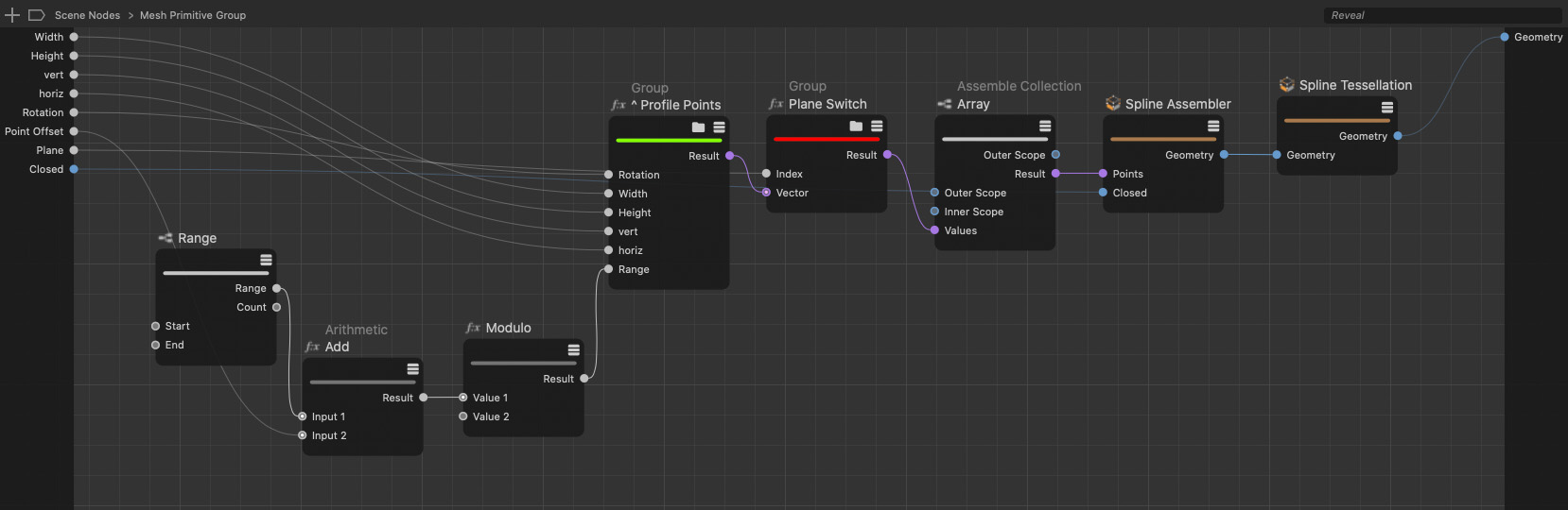 Using a Spline Assembler Node, any array of point positions can be converted to a spline curve. The Spline Tesselation Node at the end completes the spline by adding options for intermediate points.
If tangents are also to be defined, these must be assembled from two vectors each, for the left and the right direction of the spline at the respective point. To do this, use an "Assemble Collection" Node, which can also be used to assemble so-called "tuples", i.e. a data packet consisting of two separate vectors, for example. It is important that there are as many tuples as spline points. The arrays of point positions and tangents can be merged at the "Spline Assembler" Node. To ensure that the appropriate input for the tangent also appears there if required, the "Spline Type" must be set to "Bezier" at the Node.
The compiled asset of this group can be used directly in the Object Manager, e.g. with an Extrude object for polygon generation.
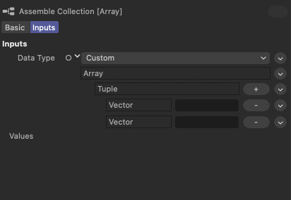 If tangents are needed, too, you can create them from two Vectors inside a Tuple. The Assemble Collection Node allows the creation of Tuples and arrays of tuples.
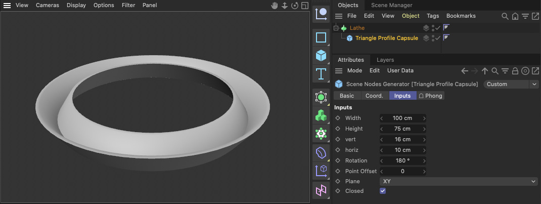 The spline capsule can be used just like a standard spline object in the Object Manager.
Create a Generator Capsule
Generators are somewhat different from the aforementioned assets because they require other objects to function. For example, think of a Boolean object or a Symmetry object which can't work until other objects have been grouped below. This object class can also be created with its own asset capsules. You can also find examples of this type already in the Asset Browser, such as the "Atom Array" that you can find in the "Geometry Generator" group.
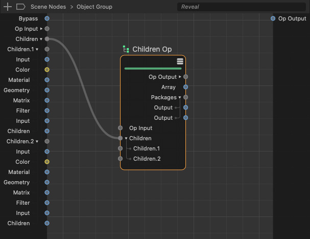 Using the Children Input of a Children Op Node as an input at the Object Group allows us to iterate over all child objects in the Object Manager later.
To create a generator asset, you need to use an "Object Group", which you can also find in the "Asset Construction" category. The "Object Group" already has an input for children, but we cannot configure this directly from within the group to any number of child objects and then read them out. It requires a trick for this.
To do this, open the Object Group and add a "Children Op" Node there. This node has a "Children" port group on the input side. Drag this port to the input side of the Object Group and have new inputs created there from this port.
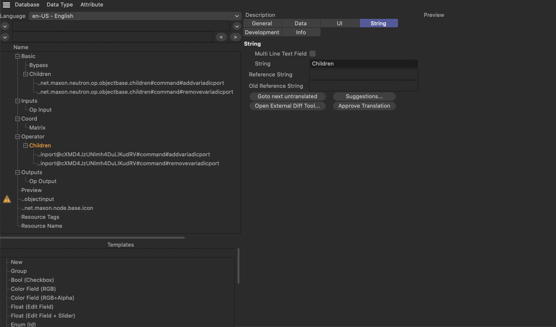 Rename the new Children input in the Ressource Editor to avoid confusion with the old Children input at the group..
To avoid confusion with the "Children" input that already exists by default, open the Resource Editor for the Object Group and find the "Children" input you just created in the "Operator" group. Rename it to "Capsule Children", for example, to avoid confusion with the old Children inputs from the "Basic" group. You can then close the Resource Editor again for the time being.
Within the group, you then link the "Op Input" of the "Children Op" Node with the "Op Input" of the group. These preparations now allow all grouped objects to be read out via the "Array" output at the "Children Op" Node using an "Iterate Collection" Node and a "Decompose Container" Node.
If an iteration is then also performed on these objects at the "Decompose Container" Node using another "Iterate Collection" Node, the positions, sizes, axis directions, materials, colors and geometries of grouped objects can be read out, among other things.
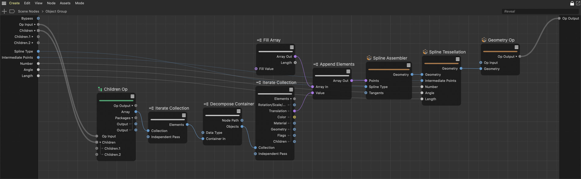 Using an Iterate Collection Node on all Objects of the Children array offers data, such as positions that we use here to place new points at a spline curve. The settings for the Spline Tesselation are made available as inputs at the group so that user can change them later directly in the Attribute Manager.
In this case, we only use the "Translation" information to create a spline curve that connects all axis centers of grouped point objects, i.e. splines or polygon objects. For this purpose, a "Spline Assembler" Node is used again, to which a "Spline Tessellation" Node is attached. Its inputs are declared as inputs to the group at the same time, so that the user can later specify the type of spline curve and its intermediate point interpolation himself. The positions of the found child objects are collected in an array by a “Append Elements” Node and then passed to the "Spline Assembler". The resulting geometry is connected to the output of the group via a "Geometry Op" Node.
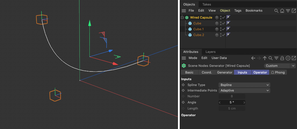 Using the asset. in the Object Manager offers an new type of generator object, that creates a spline from the positions of grouped polygon objects. In this case we used a Bspline interpolation to create a rounded curve between the three cubes.
As in the previous examples, let's compile the group into an asset and drop it into the Asset Browser. From there, the new asset can be dragged directly into the Object Manager. Once some polygon objects have been grouped there, you can see how the centers of these objects are connected with a spline curve. As is common with many generators, the grouped objects automatically become invisible in the viewport.