Project Settings
Real units
In previous Releases of Cinema 4D (prior to R12), no real units of measure were present. Although you could enter the unit "mm", this had no meaning for Cinema 4D.
This has changed in R12: a unit of 1 meter is now equal to 100 centimeters and 1 kilometer equals 1000 meters, and so on. Hence, if you change your units of measure from, for example, Meter to Centimeter, a cube 2m wide will then be displayed as being 200cm wide. The values will be converted automatically if the Use Units option is enabled.
In combination with (internal) double precision (which was increased from 32-bit to 64-bit with R12), rounding errors are a thing of the past, which means that you can model 2mm wide specks of dust and then switch to Kilometers and model a huge building in which they lie. Cinema 4D can handle this with no problems at all.
It is also possible to, for example, load objects modeled in Millimeters into a scene that contains objects modeled in Meters. The units will be converted automatically.
You can define units of measure within Cinema 4D at these locations:
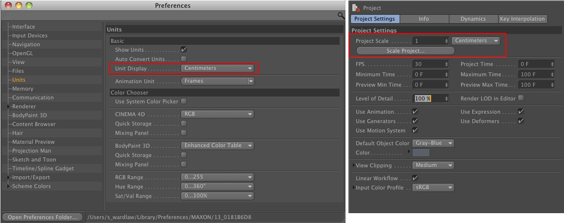
- In the Preferences menu: This setting does not affect scene parameters. Only the units displayed in the respective fields will be converted. If, for example, a value of 3 cm was defined and you switch to Meters, the field will then display a value of 0.03 m (or 0.033 yd).
- In the Project Settings: Depending on what has been defined, the scaling of the scene can in fact be modified. A 200 cm wide cube (Document Scale: Centimeters) will be 200 m wide if you switch to Meters.
Scale document
This is the most important parameter with regard to units of measure. It defines how the numerical value saved within the file will actually be interpreted - 3 meters, 3 kilometers or 3 yards, for example? A new, empty scene will always use the Project Settings’ default values. You should determine the units of measure you want to use from the very beginning of your project. Simply orient yourself to the actual scale of the objects you are creating in 3D. For example, a house would be modeled in Meters, the inner workings of a watch in Millimeters and a mountain range in Kilometers.
When importing older scenes (prior to R12), Centimeters will be the default unit of measure used (unless you have defined a different unit in the Scale setting). You can, of course, change the Document Scale at any time if you are working with very large and very small dimensions in a single scene.
![]()
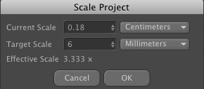
When scenes created in older versions of Cinema 4D or objects from external applications are imported into Cinema 4D they often do not have the correct units of length or none at all. This command can be used to scale the scene to the correct size.
Let’s say you have imported a hexagon bolt created in IGES with an unknown scaling. You know it’s supposed to be an M6 bolt and the document is set to the default Centimeter scaling. All you have to do is select two opposing points on the hexagon bolt and define the interval between them (values can be seen in the Coordinate Manager).
Assuming both points lie 0.18 cm apart, the following values have to be entered to scale the scene correctly:
This value defines the frame rate for the current document. This value will be applied to all animations create with this scene.
This is the time (frame) at which the Timeslider is currently positioned.
Defines the starting point of the animation tracks. This can also be a negative value, e.g. for initiating a particle stream prior to the begin of an animation.
Defines the end time for animation tracks.

These values represent the start and end time of the preview range displayed in the Animation Toolbar. These values can be modified by double-clicking on the areas shown in the image above.
This value affects how each scene object for which a specific level of detail can be selected is displayed. Such objects include all Primitives, Metaballs or all Generator objects.
The level of detail can be reduced evenly, independently from an individual object’s level of detail.
If this value is set to 100% all objects will be displayed in full detail (in accordance with the value defined in the object’s parameters).
If this value is reduced to 50% all scene objects will be displayed with only half the number of lines in the Viewport.
The value defined in the Render Settings will be applied and the value defined by the LOD will be ignored.
These four options have the same effect as those in the main Cinema 4D menu. Details regarding how they work can be found here.
Disabling this option will disable the Motion System. Alternatively, the Motion System can be disabled in the main Cinema 4D menu.
Here you can create a color that will be assigned to all objects that do not have a material assigned. 80% Gray is the color used by Cinema 4D versions prior to R12.
 If faulty depictions, as shown at left, result you should use a different Clipping region.
Due to the fact that it is possible to work in very large dimensions (e.g. kilometers) or in very small dimensions (e.g. nanometer), the display (only affects this display - the rendered display remains unaffected) can be a little strained (the Z buffer has a limited resolution and at some point can no longer discern which polygons lie behind other polygons, which results in poor display quality).
In this case you can define a Clipping region. Outside of this region (calculated from the point of view of the camera) the display will be cut off. Within the region the display will always be correct (the Near and Far values should not differ too much).
Select a region from the selection menu or do so manually via the Near and Far values, respectively.
The linear workflow (a.k.a. too many Gammas)
In short
In the past years, the idea of linear workflow (in the following referred to as lin. W) has almost been turned into a mythical process that promises to work miracles. Although linear workflow cannot produce miracles it can help you produce better images quicker and with less effort.
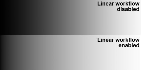
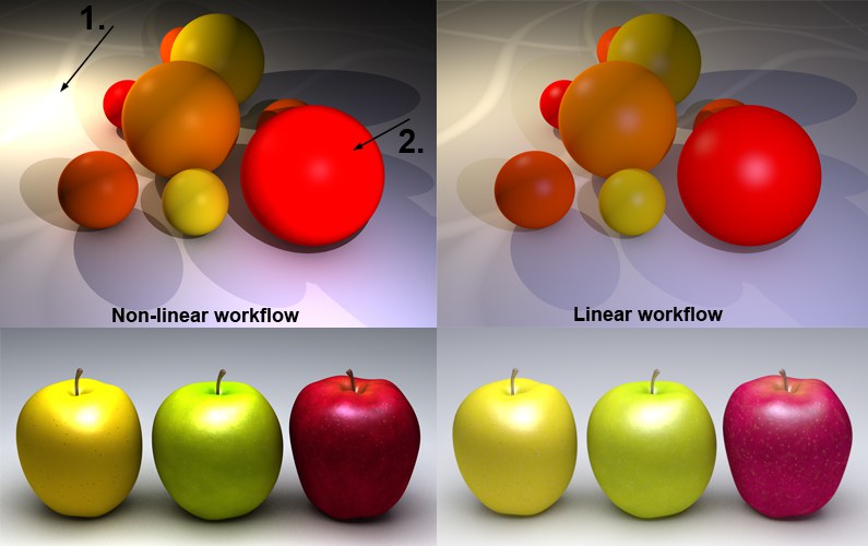 Overexposed regions will be reduced.
The effect a lin. W has can be seen in the image above. The scene is lit using two light sources, each with inverse square falloff. The quality when lin. W is used at right is dramatically better.
Lin. W offers the following advantages:
- More harmonious dispersion of light; scene appears brighter overall
- Overexposed regions will be reduced
- More natural coloration
- Summary: more realistic dispersion of light (use of light source with physically correct inverse square Falloff are recommended).
Note that all Cinema 4D-internal material colors and color gradients will be modified directly in the preview. This can also lead to confusion because, for example, grayscale gradients will look differently than before.
The color value of 128, 128, 128 at the center of a normal grayscale gradient (Linear Workflow option disabled) will change to approx. 192, 192, 192 when this option is enabled. This behavior is correct!
For those of you who are interested in the "how and why", simply read on. Everyone else can get started with rendering more beautiful images right away.
Details
The topic gamma values and the corresponding Lin. W is a result of renderers rendering with a linear Gamma value of 1 but being fed with input (textures, shaders, etc.) with a different Gamma value (most commonly 2.2 since the introduction of macOS X 10.6; previously 1.8) even though the renderer expects a Gamma value of 1.
This results in the renderer rendering "more incorrectly" (with regard to being physically correct) than it actually should.
If you now think that you rendered below-standard for the past 10 years we can confirm this with a hearty "yes and no". If the result is what you were looking for then the rendering was successful. However, you tend to get used to how your renderer works and generally end up working around its shortcomings. If, for example, a fill light was added, which ended up changing the coloration at places and resulting in an unwanted look, this might have been avoided if Lin. W had been used.
This is also the reason that older scenes don’t automatically look better if Lin. W is enabled. Older scenes were designed to work well without Lin. W. If you want to re-use older, optimized lighting configurations you should adapt these for work with Lin. W. If, however, you are satisfied with the render results there is no need to do this.
Why do gamma values exist?
Most monitors, for example, have a gamma value of 2.2. If you paint a texture in an image editing program, this image will be displayed with a gamma value of 2.2 and will be saved accordingly. Almost all images that you have created or that you will find on the internet have a gamma value of 2.2.
Only with this value will images look good on an average monitor. This has to do with the fact that images with a lower bit depth (8-bit and 16-bit) are saved in a manner that displays a brightness range that looks good to the human eye. A human eye can make out finer gradation in darker regions than in lighter regions.
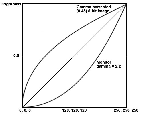 A gamma corrected 8-bit image with a gamma value of 0.45 is displayed on a monitor (gamma = 2.2) with a (for the human eye) linear brightness range.
Renderers on the other hand (including the Cinema 4D renderer) work internally with linear gamma ranges (i.e. gamma =1; defined by the prevailing algorithms) and expect the same from what they display (textures, shaders, etc.). However, this wasn’t so simple in the past. The renderer wants a gamma value of 1 but is given input with a gamma value of 2.2. It’s natural that discrepancies with the physically correct result arise.
As soon as the renderer has finished its work the rendered image’s color and brightness has to be reduced and at the same time a gamma value of 2.2. has to be applied so the image looks good when displayed on the monitor (in the image was rendered in 32-bit the gamma correction would take place and the image saved in a subsequent step).
So how does the Lin. W fit into all of this? Simple - as soon as you enable Lin. W, all elements involved in the render process (textures, shaders, etc.) will be re-calculated so the renderer sees them with the required gamma value of 1. After this correct rendering has taken place - internally, the renderer also produces images with a gamma value of 1 - the images must be converted to a gamma value befitting the display device (most often a monitor with gamma = 2.2).
That was a brief description of the reason behind Lin. W. If you want to read more about the above you can download a very informative and free .pdf file by the name "Be Gamma Correct!" by Martin Breidt (a Web search should lead you to the correct file). Don’t let it bother you that the document refers to a different 3D application from Cinema 4D - the principles are the same.
The Lin. W’s settings include the color space sRGB. This is somewhat comparable to the above-mentioned gamma value of 2.2, i.e. if an image is saved with a gamma value of 2.2 it most often reflects sRGB values.
Color Management
General
Everyone has heard of it but only few understand what it really is, even though many books have been - and still are being - written about this topic. In the following you will find a brief introduction of the issues regarding color fastness.
Surely you are familiar with the effect of an image looking perfect on your monitor (colors are exactly as you want them to be - brightness, contrast, etc. are immaculate) but when you view the same image on your colleague’s monitor or even printed out it looks completely different - mostly worse.
How does this happen?
Colleague A creates an image using an image editing program. He creates his image according to how it looks on his monitor. When finished, he saves the image - and this is where the problems start: Image editing programs have to save images with a reproducible color definition (i.e. the color profile, which is mostly RGB). Most often a color profile is selected that corresponds to the display device - for most (but not all!) monitors sRGB and for printing CMYK, etc.
This means that the red value on colleague A’s monitor has to correspond to the RGB value in the image file. Colleague A’s monitor must pass on the image’s colors exactly how the image processing program will display the RGB values. In order to do so, Colleague A’s monitor must be calibrated correctly. Over time, a monitor’s color display will change and should theoretically be calibrated every 4 weeks if being used for work with real color profiles. Regular calibration is also necessary for all input and output devices such as monitors, printers, scanners, etc.
If everything has been calculated correctly, the printed image from colleague A’s monitor should appear exactly the same on colleague C’s monitor after being scanned in. How probable this actually is can be attested to by anyone who has actually attempted such a feat (a 100% match is in fact not possible because not all devices can convert color profiles loss-free). But at least a nearly 100% match can be achieved on different monitors when calibrated correctly.
This was a simplified explanation of the issues involved with precise color management. What is basically required is a consistent, clearly-defined color profile within the creation process from image editing to the final output of the image.
And what does all this have to do with Cinema 4D?
First the good news: If you’ve never heard of color management and your renderings have always met or exceeded your requirements then you can simply ignore this parameter (and leave all Cinema 4D adjustable color profiles set to their default mode sRGB). To be honest, only very experienced artists will see the difference between images created using precise color management and those created by rule of thumb.
sRGB is the color profile that has been used for several years whenever no alternative color profile has specifically been defined. This is why about 99% of all images on the internet contain this default color profile. Even Cinema 4D versions prior to R12 saved images exclusively in the sRGB color profile.
The locations within Cinema 4D at which color profiles can be defined are listed below.
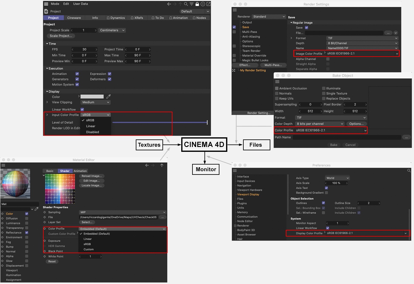 The most important color profile settings in Cinema 4D
As you can see, there are three "interfaces" from/to Cinema 4D where color profiles (or hardware profiles) can be analyzed:
-
Textures: As you know, bitmaps can be loaded into various material channels or Image Nodes. In the Project Settings you can define if and how imported color profiles should be handled. You can also define which color profile should be used if a bitmap does not contain its own integrated profile. Additionally, you can define how the individual bitmap should be used for individual channels (per bitmap shader).
The BodyPaint 3D layout also contains several commands with which and locations at which color profiles can be modified (e.g. Bitmap Layer or Change Profile...). - Monitor: Here you can define a custom (preferably calibrated) monitor hardware profile. This profile is responsible for the display of colors in Cinema 4D on your monitor, i.e. what you see in color selection fields, in the Viewport, Picture Viewer, etc. Not necessarily to be ignored if you consider how often you select colors within Cinema 4D.
- Files: Rendered bitmaps (color profiles cannot be added to movies rendered with Cinema 4D). Here you can define the output color profile that is saved with the file and used, for example, when the rendered image is opened in Photoshop.
In the attachment you will find a list of image formats with which color profiles can be used.
More information can be found under Color Management (in most cases sRGB will be correct).
Here you define 3 things:
- Whether or not the embedded color profile of textures should be used
- Which color profile should be used for textures with NO embedded color profile.
- Which color profile should color selection fields, gradients, etc. within the application use
The selected option is shown in the field below.
If a texture has an embedded color profile, these options define how the color selection fields, gradients, etc. will be displayed in Cinema 4D. sRGB is the most commonly used display mode (when in doubt, use this mode). Linear is the mode that less common and more difficult to use.
In this mode, embedded color profiles will not be taken into consideration. The sRGB color profile will be used instead. Simultaneously disabling the Linear Workflow option will reflect the mode prior to R12.