Anti-Aliasing
Antialiasing removes jagged edges from your images. It works by breaking down each pixel into sub-pixels; rather than calculate just one color for a pixel, several color values are calculated and averaged to produce the final color for the pixel.
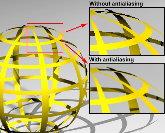 Using the settings on the Antialiasing page, you can remove jagged edges. The top right inset box shows jagged edges without antialiasing, the bottom right inset box shows the smoothed result of applying antialiasing.
How Does Antialiasing Work?
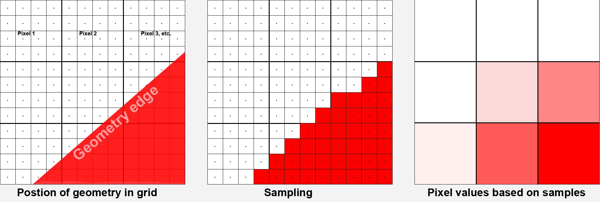 The pixels (shown as large squares) are subdivided into sub-pixels. A color value is calculated for each sub-pixel. Similar color values will be summarized into a single pixel color value.
For rendering, the render camera angle will first be divided into a pixel grid (which is defined using the Width and Height parameters in the Edit Render Settings menu). In principle, a lot can now happen in each pixel, e.g., an object edge can run through it, a texture can split the pixel in 2 different colors, etc. However, each pixel can only have a single color value. It’s a difficult task to calculate an image according to these guidelines that is visually appealing with homogenous and naturally flowing object and color edges.
One solution for this problem is to break each pixel up into sub-pixels and calculate a separate sample (=color value) for each one individually. This process is also called oversampling (or simply "sampling").
The second step is to summarize these pixels’ color values based on a defined radius around each pixel (this is done by the filters described farther below).
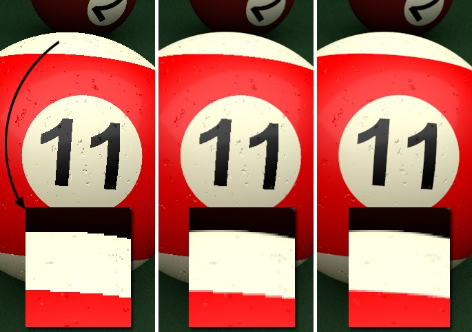 From left to right: None, Geometry (the slightly blurred texture is a result of the antialiasing filters) and Best antialiasing.
The image to be output will be calculated without antialiasing (any existing Render tags with differing settings will be ignored). Step-like structures will be recognizable at object and color edges.
This mode is particularly suited for fast test renderings for which quality does not play a role.
This is the default setting which smooths all object edges (automatically with 16x16 sub-pixels).
This enables (in addition to object smoothing) Cinema 4D’s adaptive antialiasing (additional sub-pixels will only be calculated at critical regions, i.e., for pixels whose color differs greatly from those of its neighboring pixels), which affects color edges (e.g., also shadows, objects behind transparencies, etc.). This in turn is controlled via several parameters available for this mode.
This setting is used to control Cinema 4D’s adaptive antialiasing. Sub-pixels will be calculated for neighboring pixels whose color differs too greatly; for non-critical regions (large, uniformly colored regions) no sub-pixels will be calculated if at all possible.
The default combination of these three parameters can be applied in most cases.
Min Level defines the minimum number of sub-pixels that will always be rendered. The default value of 1.1 will suffice for most cases. If, however, artefacting should occur in very detailed regions, e.g., shadow elements get swallowed, higher values should be used.
Max Level is the sub-pixel dispersion that is applied to critical regions (mostly high-contrast regions, i.e., color edges or object edges behind transparencies). This value can, for example, be increased when rendering glass to ensure the rendering of finer details.
In the image below, the difference in render results between the two settings cannot be seen at first glance. The settings should be optimized only if you want to get the utmost out of your rendering (which will, of course, result in correspondingly longer render times):
 Higher antialiasing settings are often only noticeable in the finer details. In this example, the image on the right took 10 times (!) longer to render than the image on the left.
The Threshold value defines the degree of color divergence at which Max Level should be applied for a given pixel. Small values will allow no divergence, large values will allow greater contrasts before smoothing begins.
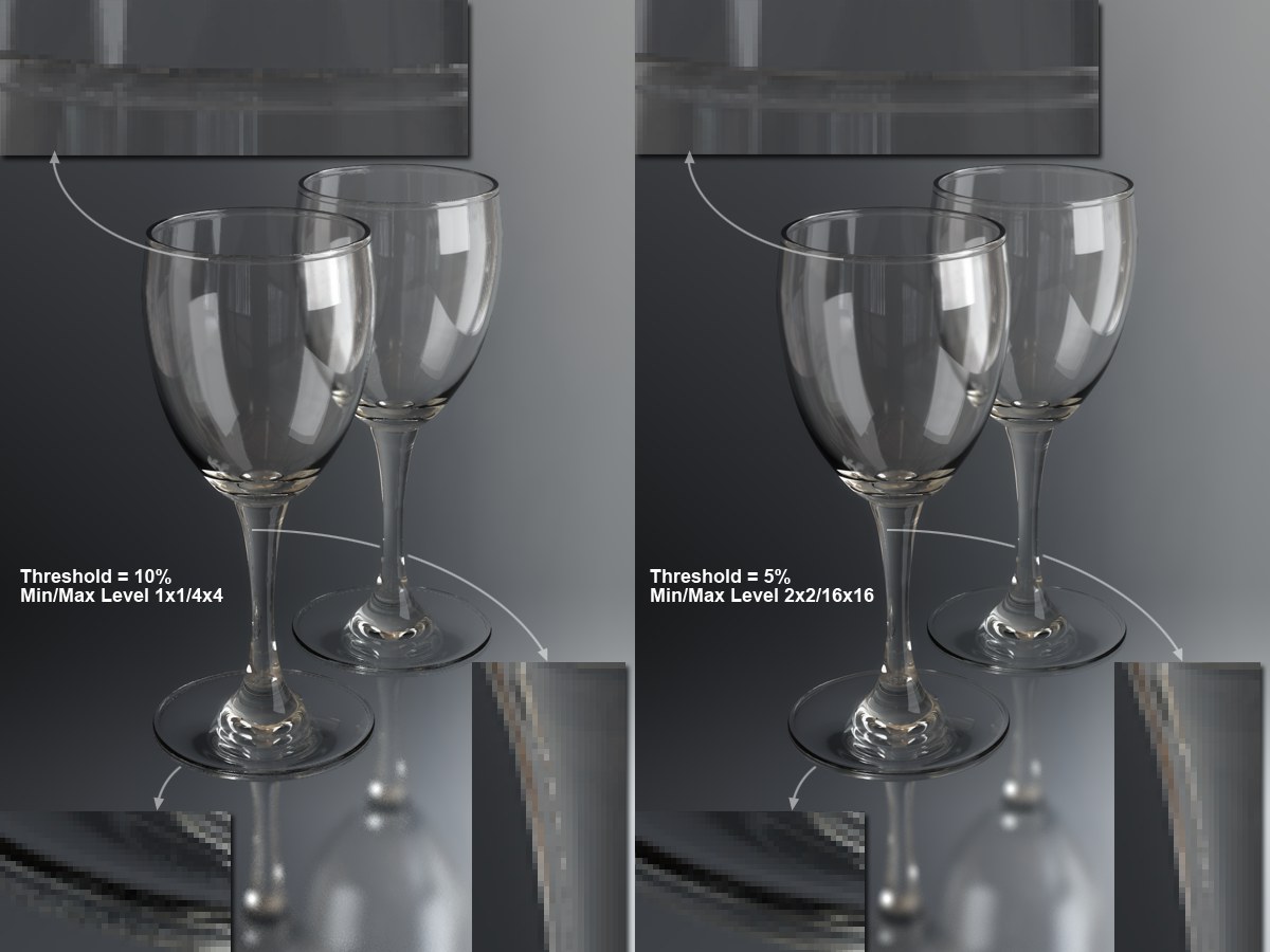
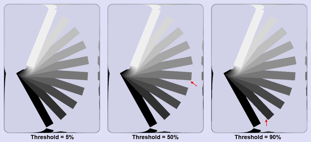 Various Threshold values at 1x1 and 16x16 for Min Level and Max Level, respectively. Higher contrasts are needed for higher Threshold values for smoothing.
The image above shows a grayscale fan behind a glass block. Why behind a glass object? As described above, without the glass, only the object edge smoothing would take place (adaptive antialiasing only works for color edges or object edge smoothing for objects that lie behind transparent objects or in reflections). As you can see, a low Threshold value results in all regions being smoothed because Cinema 4D will only allow minimal color divergence before it applies smoothing. The greater the Threshold value, the greater the contrast will have to be before smoothing is applied.
In an average scene with a Threshold (Color) value of 10%, about 40% of all pixels will be affected, whereas a Threshold value of 5% will result in 90% of all pixels being affected. A value of 0% will cause all pixels of a rendered image to be antialiased – including superfluous regions.
These three parameters have a large influence on the render speed! Settings that are too high can easily increase render times tenfold, without much noticeable difference in render quality. The default values offer very good result for most cases and moderate render times.
This tag can be used to define antialiasing settings on object level. In the Edit Render Settings menu, set Antialiasing to Best and the Min/Max Level values each to 1x1. This reflects the least amount of antialiasing for the entire scene (i.e. none). You can, however, use Render tags to define the amount of antialiasing each object should have individually. This lets you, for example, apply a high level of antialiasing to prominent foreground objects and progressively less to objects that lie correspondingly further in the background.
About render speed:
The render speed can be influenced by modifying the Compositing tag’s and Threshold’s (color) Min. Level / Max. Level parameters. Using very low settings for the Threshold (color) can really bog down your computer. In an average scene a Threshold (color) value of 10% will affect about 40% of the pixels - a value of 5% will affect about 90% of the pixels. A value of 0% will result in every single pixel being antialiased in the rendering process, even where no antialiasing is necessary.
If this option is enabled, you can specify the Min/Max Level and the Threshold separately for each object using Compositing tags.
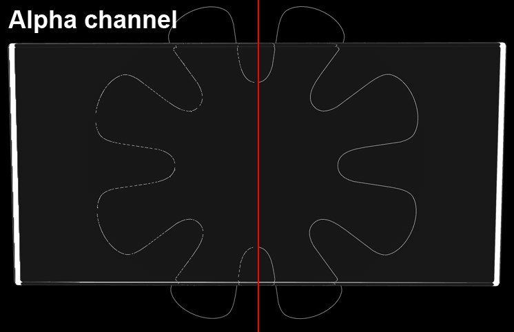 An object’s alpha channel (a Refraction pass would look similar) behind a glass cube. At left, option disabled; at right, option enabled.
In certain instances it can occur that the quality of antialiasing in Multi-Passes and Alpha channels suffers. This can happen if, for example, thin structures are placed behind refractive transparent surfaces and rendered in front of a black background. In such an instance, this option should be enabled. In many cases it would be helpful to reduce the Threshold value.
A brief explanation of how the antialiasing filter works: Depending on the antialiasing settings, a number of subpixels will be calculated per pixel whose colors are then pooled for that pixel using various functions (a pixel can only have a single color). The filter works for both Geometry (object edge smoothing) and Best (color edge smoothing) antialiasing types.
Generally speaking, the filter controls how sharp and crisp the edges will be rendered.
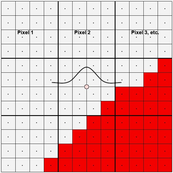
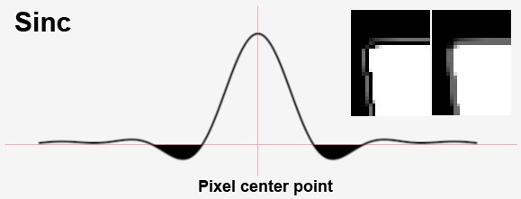
In the image above are 9 edge pixels that run diagonally across the image. Take a look at the center pixel. 16 sub-pixels were used to calculate this pixel. 15 are light gray, 1 red. These pixels form a curve (Mitchell in this case). Imagine this curve as flat around the center of a pixel. This curve then defines the degree of influence each sub-pixel should have. Because the filter size (Filter Width setting) and Filter Height (i.e. the spread within which sub-pixels will be taken into consideration) can be expanded to up to 4 pixels, the curve can be made to spread out quite a bit more. Conversely, this means that neighboring pixels for the most part see the same sub-pixel and therefore have a very similar color. Of course edges can then no longer be made to look sharp and crisp.
In the following image are curves for each of the 8 different filters, accompanied by a rendered example.
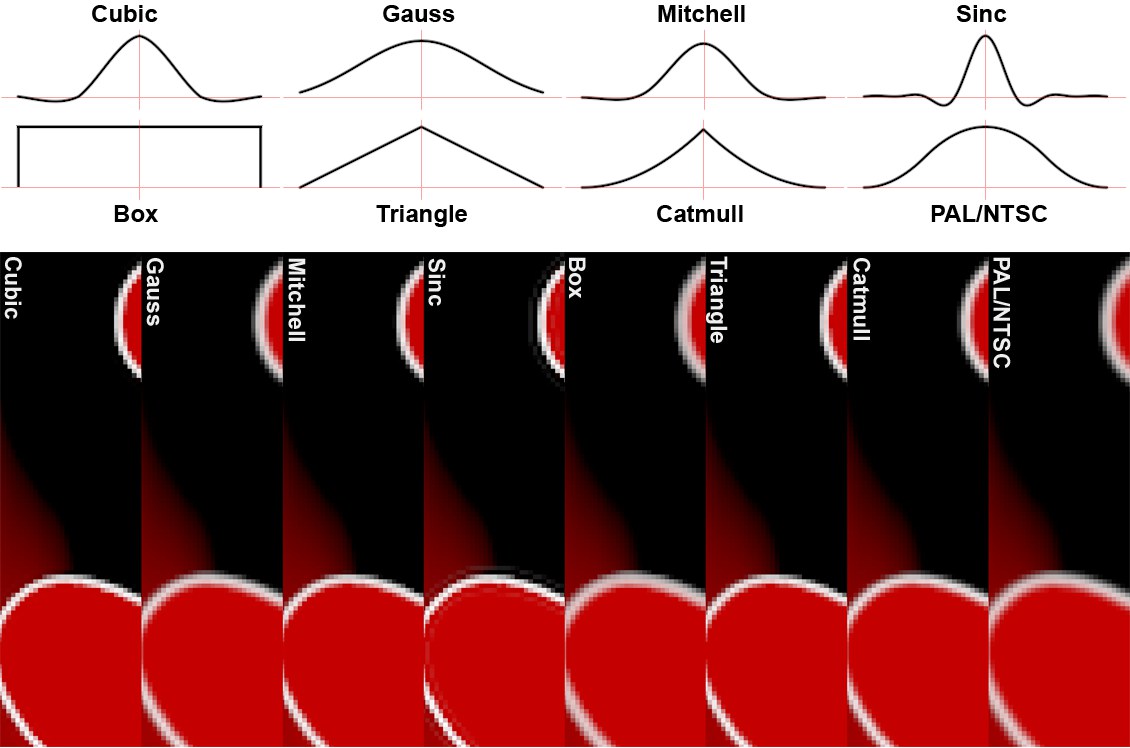
If you take a look at the curves above you will notice that several curves (Mitchell, Cubic and in particular Sinc) even fall below zero. This means that at corresponding edges, contrasting color values are rendered that are not even present in the scene. This makes the edges look sharper. This can, however, lead to problems under certain circumstances (see Clip Negative Component option).
In most cases, the filter selection has little effect on the render speed.
It’s advisable to use a soft filter for animations. Edges that are too sharp can lead to flickering.
Filter Width / Height defines how many sub-pixels (calculate from the center of the pixel outwards) will be taken into consideration when the pixel color value is calculated (see also here).
As long as the Custom Size option is enabled an ideal value for Filter Width and Filter Height will be used, which will also be displayed. The values are in relation to the pixel, i.e., a value of 0.5 for both parameters means that sub-pixels 0.5 to the left and right, and 0.5 above and below the pixel center point will be taken into consideration, i.e., all sub-pixels on the pixel surface. Higher values will extend to surrounding pixels accordingly, which will result in color edges being rendered correspondingly less sharp.
 A filter function’s negative regions can be clipped.
As you can see here here, several filters (Cubic, Mitchell, Sinc) run through regions smaller than 0. If the Clip Negative Component option is enabled, the negative regions will be clipped. What’s this good for? When using Linear Workflow, high color intensity and 32-bit rendering you may encounter problems in compositing (merging of image elements with alpha channels). Take a look at the inserts at the right of the image above: a cube was rendered to which a luminous material was assigned along with the Sinc antialiasing filter. At left the Clip Negative Component was disabled, at right it was enabled.
Scales the MIP/SAT strength globally. The local material settings (in which MIP Scale can also be defined) are also taken into consideration. The value range for the global settings ranges from 0% to 500%. A value of 100% represents a normal value; a value of 0% means that no MIP/SAT mapping, with regard to proximity, will take place; a value of 200%, for example, represents a doubling of the MIP/SAT mapping’s strength.
This value should be increased when using highly detailed textures that are directly facing the camera. This will result in a better display of continuous lines – without interruption – by the antialiasing.
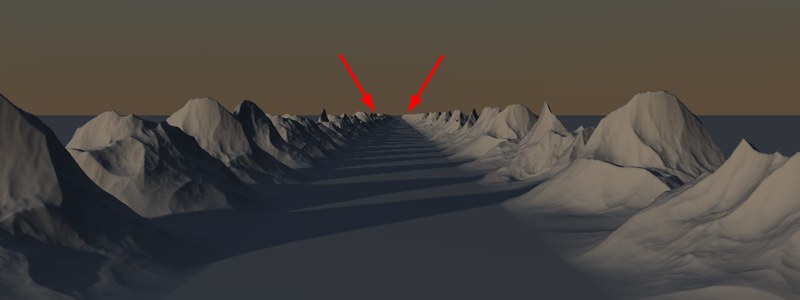 The Raytracer renders these types of scenes much faster than the Scanliner. The marked area, for example, contains a large number of polygons per pixel.
Since the introduction of Render Instances it is possible to render an innumerable number of complex objects. Let’s say you have a complete house consisting of thousands of polygons located at your scene’s horizon, which is so far away from the camera that it would only be about one pixel in size when rendered. The Small Fragments functionality is designed to render just such regions more effectively (as well as regions with high levels of Subsurface Scattering).
Cinema 4D has two internal render processes, the "Scanliner" and the "Raytracer", that were applied automatically without the user having a say in the matter. With regard to the aforementioned scene, the "Raytracer" will render a scene of this type much faster than the "Scanliner".
You might say that the Raytracer should be used to render every scene. Unfortunately this method bears the disadvantage that it delivers a lower quality antialiasing and is slower when rendering scenes of contrasting nature like the one in the image above. This is what the Hybrid option is for, which combines the best of both methods. Simply put, all image regions where more than 50 polygons per pixel are visible will be rendered by the Raytracer and the Scanliner will take care of the remaining regions. The default Hybrid option should therefore be the correct choice for most renderings. The Scanline Only option is the render method used in pre-R11.5 versions.
Raytrace Only should only be used for scenes as the one described above. The scene will render faster than with Hybrid (but the antialiasing will be of slightly lesser quality).