Option
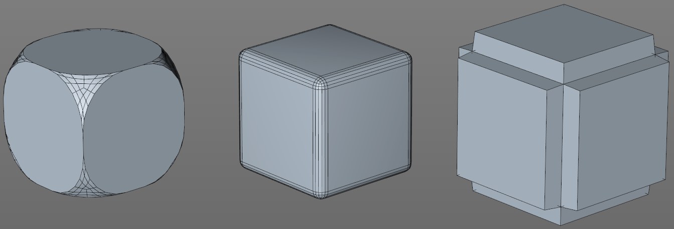 The Bevel Deformer’s effect on a cube. From left to right: points, edges, polygons.
Here you can define which polygon elements should be beveled.
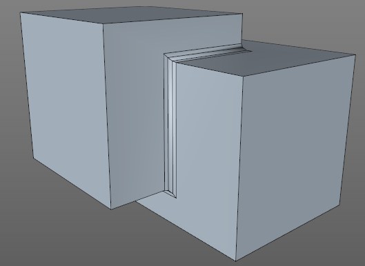
 The Bevel Deformer (Bevel Mode = Solid) only affects the selected edges on the object at the left. SDS smooths accordingly.
Without any additional changes to the settings, the Bevel Deformer affects all elements of a given object. On the practical side you can use a Point, Edge or Polygon Selection tag to restrict the effect to specific elements.
Simply drag a Selection tag into the Selection field (the Add and Remove buttons can be used to add or remove Selection fields) or type the tag’s name into the field. The tag will only work if the correct working mode is selected, e.g., an Edge Selection tag will have no effect when in Use Polygon mode.
Note in conjunction with this that the Boole object (under the circumstances described on that page) will create an invisible Selection tag named "I", which can also be intered into this field, and will only bevel the cut edges.
In addition to using Selection tags, the Bevel Deformer’s effect can also be restricted using an automatic edge bevel by defining the angle between both edges of the corner polygons. If the angle between both edge polygons is larger than the Angle Threshold value, the edge will be beveled, if the angle is smaller, no bevel will take place.
This setting is only available if Component Mode is set to Edges.
Identical settings with the Bevel tool
The settings described below work exactly like those for the Bevel tool. This is why we have not included any sample images here - links are provided instead).
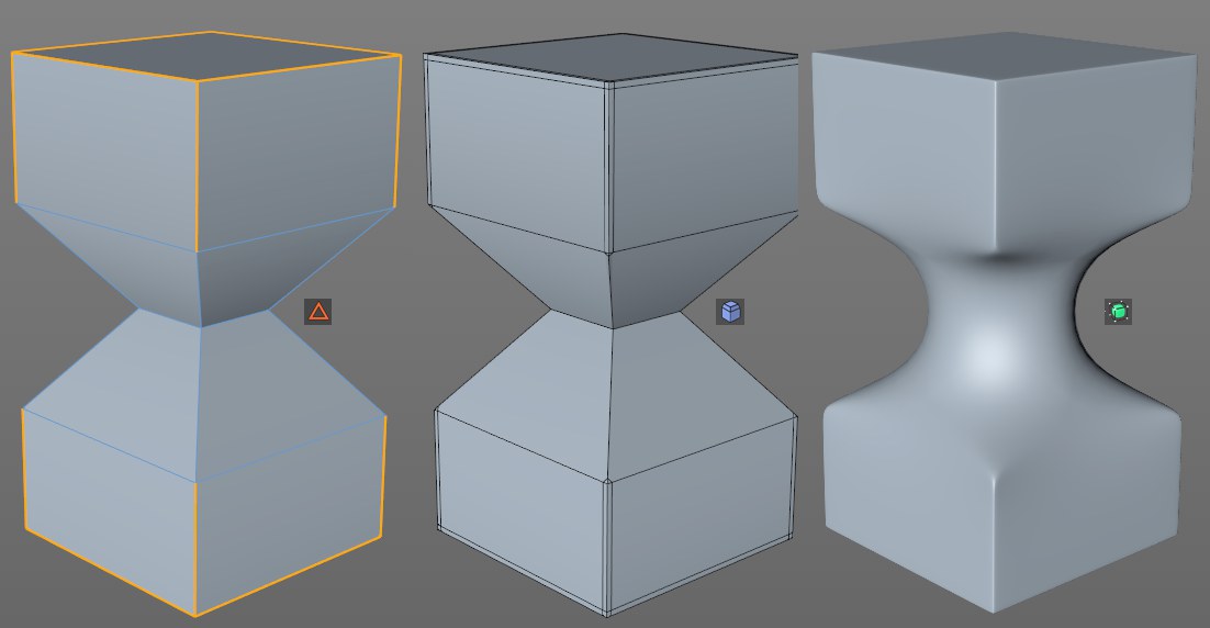
You can determine if selected elements should be chamfered (Chamfer) - which is what most users define as ,beveling’ - or if parallel edges (Solid) should be added along the neighboring polygon. The latter is used to accentuate edges (and only these; Solid does not work in Use Point or Use Polygon mode) on Subdivision Surface objects.
An example can be found under Bevel Mode.
You can select from the following 3 modes:
When beveling in Use Edge mode, at least 2 new (outer)edges will be created from the original edge that run parallel to this edge on each of the neighboring polygons (a new surface will be created within the two lines). The (equal) distance of both outer edges from the original edge to be beveled is defined as an absolute value by the Offset setting.
When in Use Polygon Mode, all selected surfaces will be scaled and extruded. The scaling is defined by Offset, whose effect is absolute when set to Fixed Distance.
When in Use Point mode, a corner consisting of a selected point will be dissolved and new points will be created along all edges belonging to this point, which are then connected via a polygon surface. The absolute Offset value defines the distance from the original point.
This mode only works at locations at which 3 edges conjoin at a single point (in other cases the Fixed Distance algorithm will work - see above).
An attempt will be made to give the rounded corner a spherical (increase the Subdivision value) shape, which the other modes generally do not do. Use the Offset value to define the sphere’s radius. A "real" corner will be created - as you know from NURBS CAD programs.
When beveling in Use Edge mode, at least 2 new (outer)edges will be created from the original edge that run parallel along the neighboring polygons (a new surface will be created between these lines). The (equal) distance between both outer edges from the original edge to be beveled is defined as a percentage by the Offset value. The percent value is based on the distance from the next edge. A value of 100% will make them congruent (but will not merge them!).
When in Use Polygon Mode, all selected surfaces will be scaled and extruded. The scaling is defined by Offset, whose effect will be in relation to the original scale when set to Proportional. If surfaces of differing sizes are beveled, a value of 50% will result in all surfaces simultaneously reaching the null point (when 2 opposing edges approach each other, each with 50%, they will collide).
When in Use Point mode, a corner consisting of a selected point will be dissolved and new points will be created along all edges belonging to this point, which are then connected via a polygon surface. The Offset value defines the distance to the next point as a percentage.
An example can be found under Offset Mode.
This is the general unit of measure for the bevel width, i.e., the smaller the Offset value, the smaller the edge, chamfer, polygon or corner resolution. The Offset value can be limited in size by enabling the Limit option. As soon as points/edges are congruent they will be merged.
This setting can be used to subdivide new regions created by the Bevel tool any number of times. If this value is set to 0, edges will not be rounded. Hard chamfers and edges will be created. Higher values should be used in particular in conjunction with the Shape value described below to create rounded (’soft’) edges.
Subdivision mostly occurs by creating parallel edges. In the case of point, polygon or corner dissolution, a suitable mesh will be created.
An example can be found under Subdivision.
The by default rounded edge created by the Subdivision setting (for example, if yo bevel a cube’s edge and view it from the side you will see a raised surface) can be moved in a positive or negative direction using the Depth setting.
An example can be found under Depth.
If newly created points or edges meet when the Offset value is increased, this option defines whether or not they should merge or move beyond this limit. In most cases this option should be enabled. Otherwise a lot of overlapping polygons can be created.
An example can be found under Limit.