Subdivision Surface
![]()
For character designing especially, but for general modeling also, Subdivision Surfaces is one of the most powerful sculpting tools available to the 3D artist. With point weighting, edge weighting and the subdivision surfaces of Subdivision Surface, you can craft any shape at all — from high performance sports cars to characters that you can pose and animate easily.
Subdivision Surfaces objects are also well-suited to animation. Complex objects can be created using a relatively low number of control points. To animate these objects — perhaps using PLA or Soft IK — you animate these control points. This is a far quicker and easier process than, for example, using PLA to animate a character that has over 100,000 polygons.
The Subdivision Surface object uses an algorithm to subdivide and round the object interactively — a process termed subdivision surfaces. This is an extremely quick and simple way to create organic forms or, with the help of edge and point weighting, firmer shapes also. There are various ways to go about building your Subdivision Surface models. Techniques include starting from a simple object such as a cube or creating the points manually one by one (join them together with the Bridge tool or Create Polygon tool).
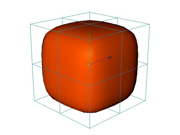
If you start with a Cube object, convert the cube to polygons with the Make Editable command and use tools from the menu to extrude, bevel, knife and so on to craft the surface. To firm up the model, use point, edge and polygon weighting.
Although in principle you can use any type of object with Subdivision Surface, most of the time you will work with polygons so that you can use the various polygon tools such as Knife and Bevel.
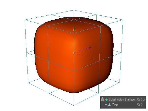 Subdivision Surface object and cage object visible
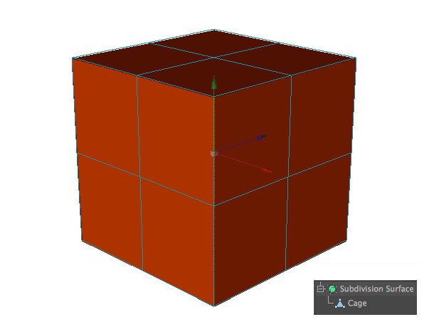 Only cage object visible
Weighting Subdivision Surface models
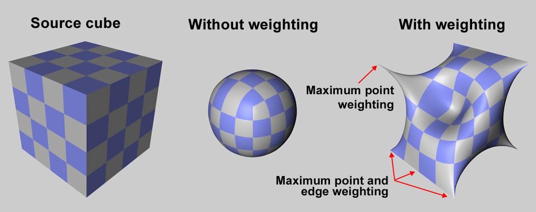
You can weight Subdivision Surface models in one of two ways: interactively, or manually using the Live Selection tool.
Interactive weighting
Select the elements (i.e. points, edges or polygons) that you want to weight. Hold down the period key (.) and drag left or right to set the weighting for the selected elements. The more weight you apply, the harder the surface will try to reach it.
To set the minimum and maximum weighting that you can apply by dragging, select the Live Selection tool and, in the Attribute Manager, enter the desired values into the Interactive Minimum and Maximum boxes.
Three modes are available: Point, Edge and Polygon (note that the weighting can fail, depending on which algorithm is used - and contrary to the Catmull-Clark-only scanrio shown in the image below).
Point mode
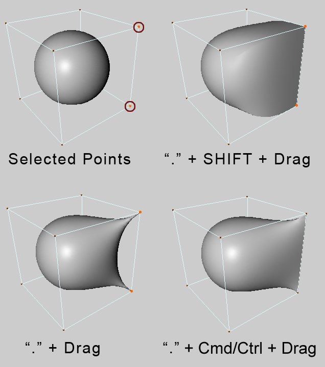 Selected points. ‘.’ + drag. ‘.’ + Shift-drag. ‘.’ + Ctrl-drag.
To weight selected points, hold down the period key (‘.’) and drag. To weight selected points and all edges connected to them, hold down the period key and Shift+drag. To weight selected points and the edges between them, hold down the period key and Ctrl/Cmd+drag.
Edge mode
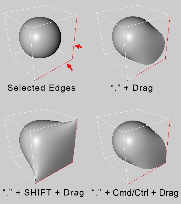 Selected edges. ‘.’ + drag. ‘.’ + Shift-drag. ‘.’ + Ctrl-drag.
To weight selected edges, hold down the period key (‘.’) and drag. To weight selected edges and all points connected to them, hold down the period key and Shift+drag. To weight selected edges and their shared points, hold down the period key and Ctrl/Cmd+drag.
Polygon mode
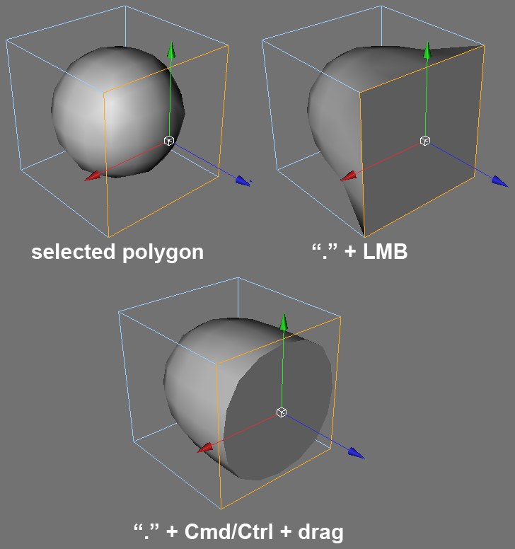 Selected polygon. ‘.’ + drag. ‘.’ + Ctrl-drag.
To weight all points and edges of the selected polygons, hold down the period key (‘.’) and drag. To weight only the edges of the selected polygons, hold down the period key and Ctrl/Cmd+drag.
Manual weighting
Select the elements (i.e. points, edges or polygons) that you want to weight. Select the Live Selection tool. You can now edit the Subdivision Surface weighting parameters in the Attribute Manager on the Subdivision Surface Weights tab.
To assign a specific weight to the selected elements such as 60%, set Mode to Set, set Strength to the desired value and click the Set button. To add or subtract weight, set Mode to Add or Sub, set Strength to the amount that you want to add or subtract and click Set.
Modeling with Subdivision Surface
Keep the following in mind when modeling with Subdivision Surface:
- A polygon should have one neighbor only per edge, otherwise the surface will tear. Sometimes you can repair a torn surface with the Optimize command from the menu.
 Here two polygons overlap each other on the left side of the object — as a result, the polygon on the right has more than one neighbor and the surface is torn.
- Only connected polygons are rounded. To see which polygons are connected, select a surface, then use Select / Select Connected. If you want to connect overlapping polygons, use the Mesh / Remove / Optimize command.
The sides of the cube are not connected to one another (left). The cube on the right is one piece.
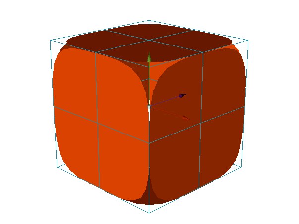
- Use rectangles in preference to triangles — triangles tend to disrupt the smooth flow of the Subdivision Surface surface. However, do not be afraid to use triangles if you must. Place the triangles in areas where there are lots of points close together, to confine the distortion to a small area. You can often avoid visible distortion by tucking the triangles away in the less critical areas.
- (1) Q switches the Subdivision Surfaces on and off, i.e., toggles between cage display and subdivision surfaces display.
- (2) Hold down the 9 key to temporarily switch on the Live Selection tool. Drag over points, edges or polygons (whichever mode is active) to select.
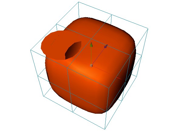
Examples
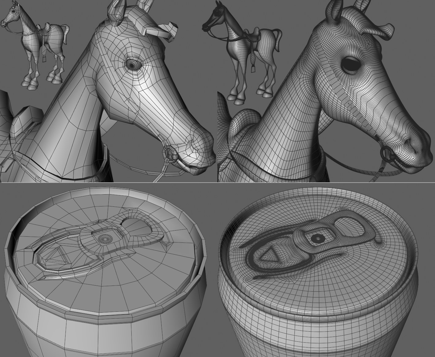
On the left of the image above are the modeled mesh objects and the same models after being smoothed with a Subdivision Surfaces object on the right. You can also model technical models with sharp edges. Sharp edges on Subdivision Surfaces objects always result at those locations with detailed geometry. Sharp edges are also created where parallel edges lie very close to each other where geometry curves. The can in the image above was created using a low-res Lathe objects. The polygon object was made editable and subsequently fine-tuned using structure tools. The opening tab is a separate object.