Object Properties
Defines the number of isoparms used to display the Sweep object when the isoparm display mode is active.
Determines the size of the contour at the end of the path. The contour is 100% at the start of the path and the size is interpolated in between.
Defines the rotation about the Z axis that the contour has passed through by the time it reaches the end of the path.
Works like End Growth, except that the Sweep object can be adjusted from the opposite end of the spline, i.e., from the spline’s start along its length.
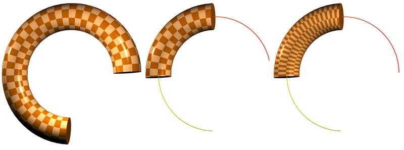
This option can be used to let a spline grow. A value of 100% will result in the spline contour being extended along the entire path. If applied to a closed spline, caps (without rounding) can be defined for intermediate stages.
Defines the size of the sweep. 100% means the contour spline is swept along the entire path. If the path is closed, you can set caps (but not rounding) when the growth is less than 100%.
For example, you can gradually write a word by using a circle spline (e.g., radius 4, XY plane) as the contour and a spline in the shape of the handwriting as the path. Finally, record two keyframes for Growth.

If this option is enabled, the contour is swept in a parallel manner (i.e. it is not rotated at all).
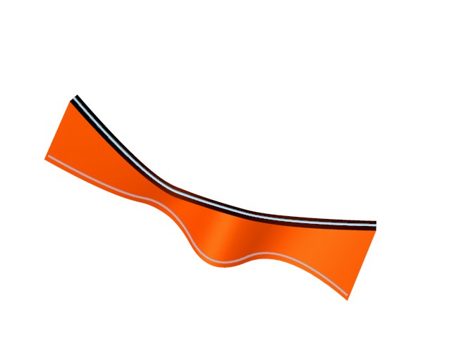
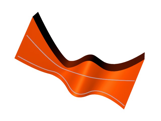
This option is enabled by default. It is ignored if a rail path is used. It causes the contour spline to be scaled at hard edges in order to maintain a constant thickness throughout the sweep. The following star-shaped path illustrates the effect.
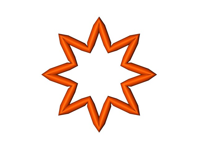
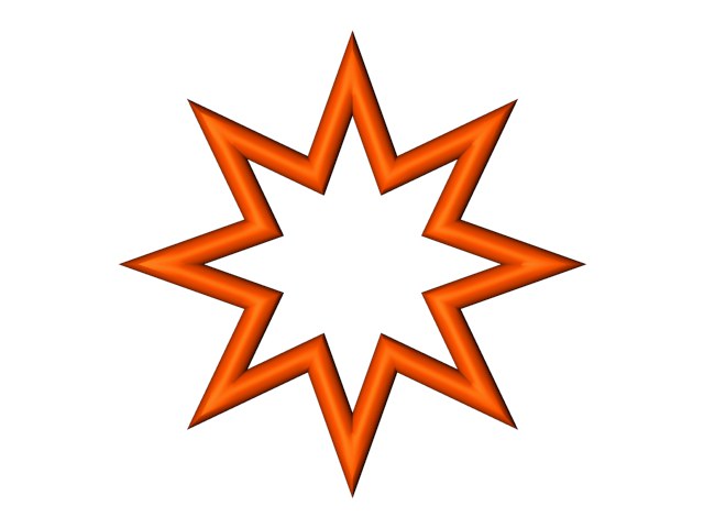
Constant Cross Section enabled (left) and disabled (right).
If Banking is enabled, the contour spline will lean into the curves of the path spline (CINEMA 4D will calculate the banking by considering the curvature of the path). The initial banking angle is set to the average plane of the path spline, which is calculated from the position of the path’s spline points. The banking angle must be chosen at random for straight lines since they cannot define a plane. In this case, turn off banking to make the contour will run parallel to the path spline’s XZ plane.
This setting is only used if you have changed the value for Growth. Its effect is, by and large, only noticeable with animated growth. If the option is disabled, the animation growth is smooth. However, if you enable Keep Segments, the sweep grows segment by segment. The positions of the segments are determined by the path spline’s interpolation type (Type). An adaptive path spline will usually lead to a jerky growth animation if Keep Segments is enabled.
If this option is enabled, the rail spline will influence the rotation of the contour about its Z axis.
The Z-rotation applied to each contour position is equal to the angle between the contour’s local +X axis and the projection onto the contour’s local XY axis of the vector that connects the contour’s local origin to the matching point on the rail spline. This vector connects spline points on the path to corresponding spline points on the rail and applies linear interpolation to determine corresponding points on paths of the splines between points.
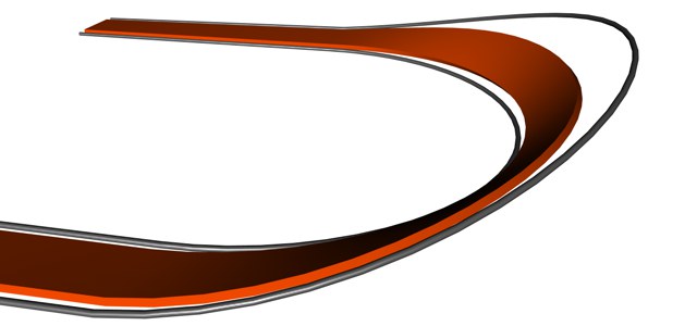
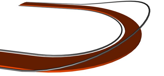
Use Rail Direction enabled (left) and disabled (right).
If this option is enabled, the contour spline will be placed between the path and the rail; otherwise, the rail controls the contour’s rotation about its Z axis (provided Use Rail Direction is enabled).
2-Rail enabled (left) and disabled (right).
If this option is enabled, the rail spline can be used to alter the scale of the contour along the path. The scale factor applied to each contour position is equal to the distance of the vector connecting the contour’s local origin to the matching point on the rail spline. This vector connects spline points on the path to corresponding spline points on the rail and applies linear interpolation to determine corresponding points on paths of the splines between points.
Flips (i.e. reverses the direction of) the Normals of the Sweep object. Usually, CINEMA 4D will point the Normals in the correct direction. However, with open contours it is not possible for CINEMA 4D to know which way they should point. In this case, you can control the direction of the Normals, either by changing the direction of the spline or by enabling the Flip Normals option. This option does not effect the caps, since their Normals are always calculated correctly.
 Left, the object’s initial state (Start Growth=0%; End Growth=100%). The growth was restricted in both examples to the right: Center Stick UVs deactivated; right Stick UVs active.
A Sweep object’s U-coordinates normally range from 0 to 1 over the entire length of the spline. If the length of the Sweep object is reduced using either Start Growth or End Growth, the Stick UVs setting defines if U should continue to run along the entire length of the spline or if it should adapt to the length of the spline. The latter option will scale an applied texture when the Growth settings are modified.
 Details
Use these function graphs to adjust the diameter of the Sweep object as desired along its entire length (the X axis symbolizes the spline length).
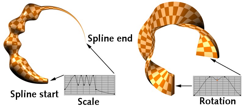 Left:Scale function graph; right: Rotate function graph.
Use this function graph to twist the Sweep object as desired along its entire length (the X axis symbolizes the spline length). The extent to which the rotation takes place is defined with the From (minimum) and To (maximum) settings, explained below.
Imagine these settings placed on the Y axis of the Rotation function graph. From represents null and To the maximum value. These settings are used to define the outer most rotational limits for the rotation of the Sweep object.
The rotation defined here will be added to any existing End Rotation value.