Spline Sketch
![]()
The Spline Sketch tool, for which you don’t have to switch to the Use Points mode (it can be used in the normal Use Model mode), replaces the previous Spline Freehand tool and can also do a lot more. The Spline Sketch tool can be used to draw directly in the Viewport (and works especially well in conjunction with tablets) and can be used to edit (e.g., redirect or smooth splines, connect splines or spline segments) existing splines.
When a new spline is created, a Bézier spline will be created by default. When existing splines are edited, their original spline type will be maintained.
The Snap settings will be observed by the Spline Sketch tool. The 3D Snapping function is especially useful because it lets you draw a spline directly onto an object surface.
Use
After activating the tool, click and drag in the Viewport to start drawing a spline. As soon as you release the LMB the spline will be created.
When sketching in space, the spline will always be drawn perpendicular to the angle of view on the layer that runs through the world origin.
The following functions are available:
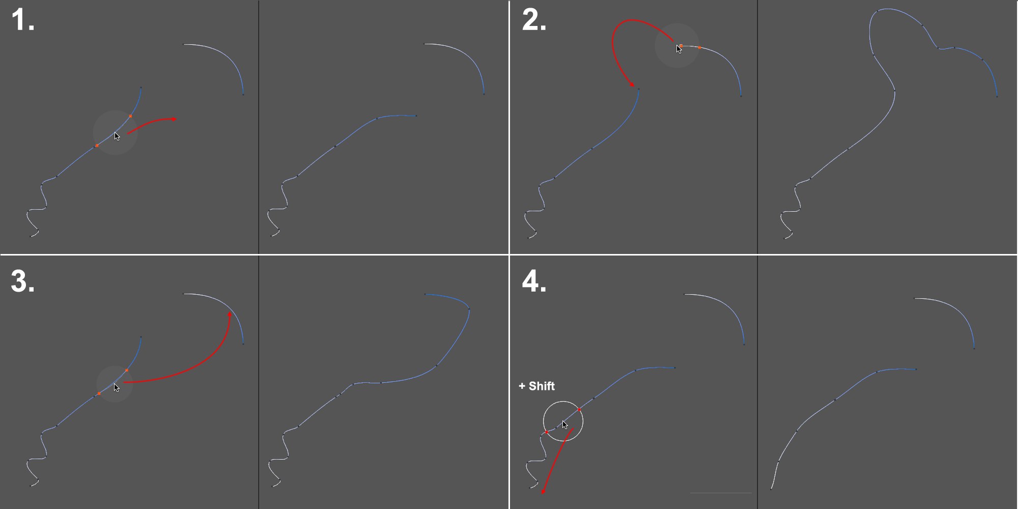 A spline with 2 segments is edited with the Spline Sketch tool.
-
A spline can be grabbed at any location and edited from that location (see also below).
-
Separate splines and spline segments of a spline can be connected at their ends. If a spline segment’s start and end points are connected the spline will be closed.
-
Separate splines and spline segments of a spline can be connected anywhere along the spline.
- Pressing the Shift key will temporarily switch to the Spline Smooth tool (the previously defined settings for this tool will be applied).
If you want to unify spline segments or 2 separate splines, select the splines first. The start and end points of the tool’s marker must lie on different splines or segments. 2 separate spline objects will be combined into a single spline.
Note the tool’s cursor at the start and end of the operation:
 The bottom section is combined in the middle with the top section.
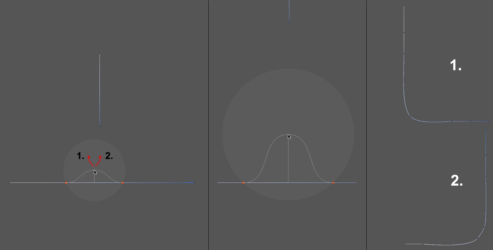
The radius that can be defined in the tool’s menu (or interactively using the MMB) is the area within which the tool can affect splines. In the preview you will that a curve defines 1 to 2 points in the radius with the spline (colored dots) and the cursor itself. The points define possible connecting points for the newly created spline. The curve itself is only a reference. What’s important is the direction in which the cursor moves when you click. If it moves left a new spline shape will be created similar to the shape to the right. If the cursor is moved away from the spline (with the LMB pressed) everything at the left of the right dot will be deleted.
However, if the cursor is moved back over the existing spline (see image below) or over a new spline segment before the operation is completed, the cursor’s circular range indicator will again be displayed and the Spline Sketch tool can be attached to the existing spline or the new spline segment.
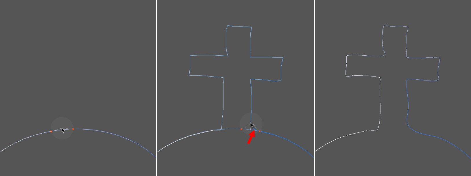
In the example above, a spline segment was added to an existing spline. The direction in which the cursor is moved for this operation is important. The movement in the center image should not be to the left in the direction of the beginning of the spline but to the right towards the spline end (note the blue preview within the tool’s radius that indicates the direction to be used).
The tool’s range indicator can be turned off temporarily by pressing the Ctrl/Cmd key or setting Radius to 0. This can be necessary, for example, if you want to create a new segment in close proximity parallel to existing splines.