Staircases
Various objects and shapes have to be combined to create a staircase. Certain norms and rules have to be adhered to in order to create a realistic-looking staircase. Cinema 4D offers a practical tool in the form f two parametric presets, which let you create straight or curved custom staircases with just a few clicks.
The parametric object used for creating straight staircases can be found in the Content Browser’s Presets / 3D Objects Vol1 / Architectural Elements / Straight Staircases directory. Double-click on the preview image to load the staircase into your scene. If the Straight Staircase Null object is selected, its settings will be made available in the Attribute Manager. The User Data menu contains numerous settings for adjusting the type and size of steps.
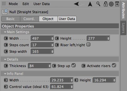 The User Data menu’s settings for a straight staircase.
Adjusting the stairs’ dimensions
In the Main Settings menu you will find the basic settings used to define the steps’ Width and Rise as well as the Step Count and the Step Width. As a rule, the staircase will have its origin at the Straight Staircase Null object’s location. Enable the Step Up option if you do not want the staircase to start with a raised step. This option is located in the Details menu. The tread surface of the first step will then lie at the same height as the Straight Staircase Null object.
The Height value defines the overall height of the staircase. If negative values are used, the staircase will be generated downwards from the Straight Staircase Null object’s position. This value, together with the Width value define the degree of ascent (or descent) of the staircase - the Width value defines the length of the staircase along the Straight Staircase Null object’s Z axis.
The Steps Count value defines the number of steps the staircase has. Even though you are free to enter any value that suits your needs, there are certain rules and norms that have to be adhered to so the staircase is ergonomically feasible. Cinema 4D takes this work off your hands because it automatically calculates the ratio of steps to the degree of ascent (or descent). This information is displayed in the Info Panel menu. The Control value (ideal 63) setting shows the calculated ratio. As the setting’s name shows, a value of around 63 represents the most realistic ratio for an ergonomically correct staircase. Since size of the staircase is often dependent on other factors, the Steps Count value is a good way of adapting the overall number of steps if the Control value (ideal 63) is not ideal. The Width and Height values can also be found in the Info Panel menu, which display the width and height of the individual steps. All values in the Info Panel menu are calculated based on the information provided in the Main Settings menu.
The Step Width setting in the Main Settings menu defines the width of the steps and therewith the staircase itself.
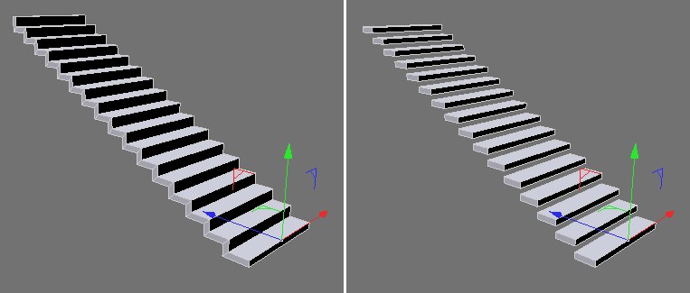 A staircase can be a free floating or massive construction.
Defining the type of staircase
In addition to the size of the staircase and the stair count, its construction type can also be defined. The term ‘riser’ refers to the vertical section connecting two steps. This section can, however, be hidden by disabling the Active Risers option in the Details menu. Only the tread section of the staircase will remain. Their thickness can be defined using the Thickness setting in the Details menu.
If Active Risers is enabled, very high Thickness values can cause polygons to intersect at the beginning or end of the staircase. If this occurs, disable the Riser left/right option in the Main Settings menu. This option defines whether or not the staircase should begin and end with a vertical element. However, this will only work in conjunction with an active Active Risers option.
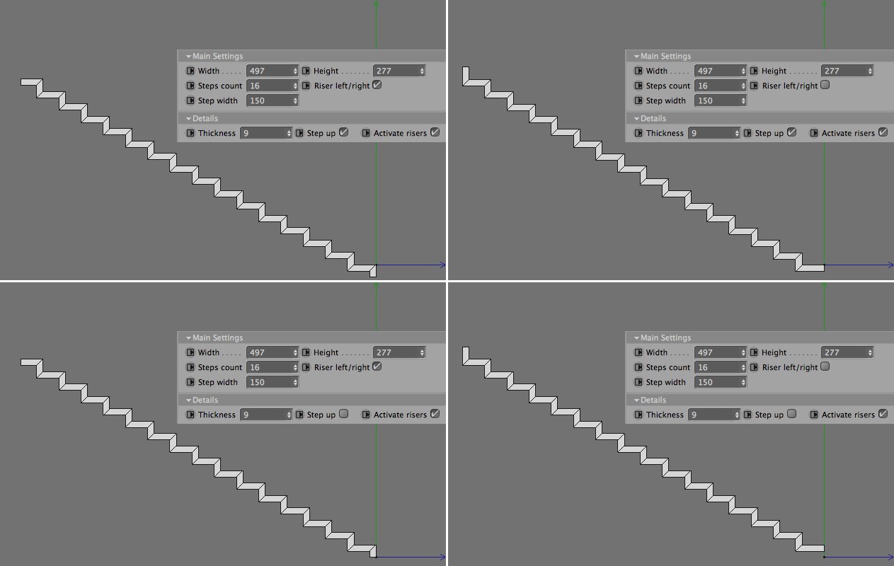 Various types of end shapes can be created using different combinations of the Riser left/right and Step up settings.
A spiral staircase can be found as a parametric object in the Content Browser’s Presets / 3D Objects Vol1 / Architectural Elements / Staircases directory. Double-click on the preview image to load the staircase into your scene. Open the Spiral Staircase - Modular Null object in the Object Manager to reveal its hierarchy, including the Spiral Staircase Null object. The Spiral Staircase Null object offers a wide range of settings in its User Data menu with which the spiral staircase can be modified.
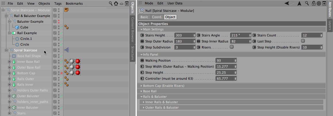 Various User Data settings can be used to customize the spiral staircase.
The Child objects of the Rail & Baluster Example object are used to create the hand rails and balusters. These objects can be replaced by custom shapes, if desired, which do not necessarily have to be placed into this hierarchy. This will be discussed in more detail in the description of the Rails & Baluster User Data menu.
 The Spiral Staircase Null object’s Main Settings menu contains the core settings for modifying the rotation and size of the spiral staircase.
Adjusting the staircase’s scale
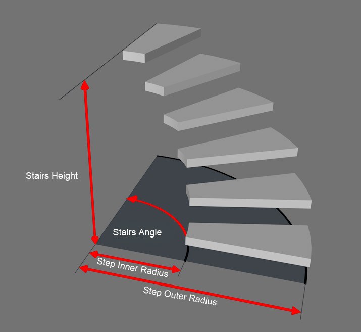
In the Main Settings menu you will find all fundamental settings required for defining the staircase’s degree of rotation and the angle of ascent (or descent) as well as the number of steps and their width. The staircase winds around the Spiral Staircase Null object’s positive Y axis. The Stairs Height value defines the overall height of the staircase. The Last Step option affects the vertical distance between the first and last tread surfaces. If disabled, the last step at the top of the staircase will be omitted.
The Stairs Angle value defines the staircase’s degree of rotation. Negative values will rotate the staircase in the opposite direction. The staircase’s radius is defined using the Step Outer Radius and Step Inner Radius values. The Step Outer Radius value defines the vertical distance of the outer step edges from the Spiral Staircase Null object’s Y axis; the Step Inner Radius value defines the distance of the inner step edges from the staircase’s rotational axis.
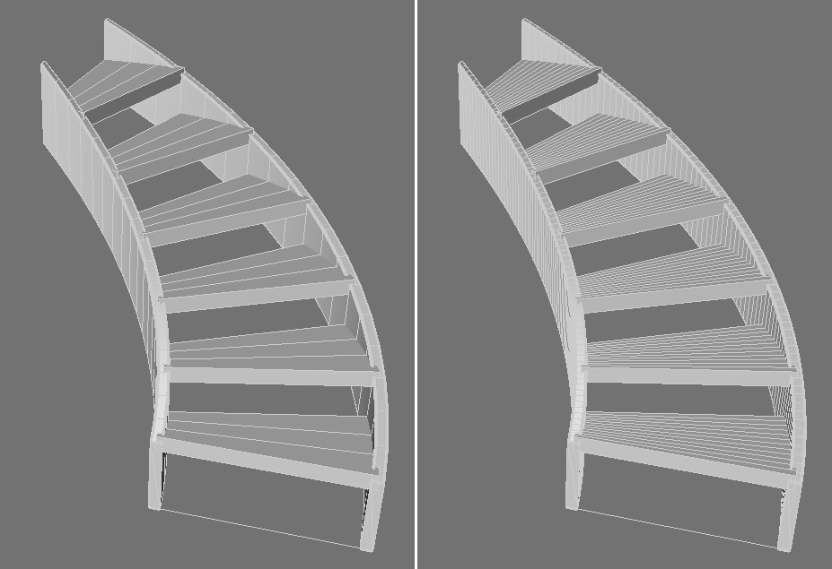 The Step Subdivision value can be used to define the step subdivision and the stringer (outer siding). At the left a small Step Subdivision value, at right a larger value.
The step subdivision and the stringer is defined using the Step Subdivision value. The number of steps is defined using the Stairs Count value. Even though you are free to enter any value that suits your needs, there are certain rules and norms that have to be adhered to so the staircase is ergonomically feasible The Controller value in the Info Panel menu displays the ratio of steps to the degree of ascent. This value is calculated automatically by Cinema 4D and is based on the settings defined in the Main Settings menu. An ideal ration is approximately 63. If the ratio for your staircase deviates too much from this value, the Stairs Count, Stairs Height and Stairs Angle values can be used to adjust the ratio.
The Info Panel menu’s Step Width (Outer Radius - Walking Positions) and Step Height values are primarily calculated using the Main Settings menu’s settings. The Walking Position value can, however, be edited manually. This value does not affect the shape of the staircase. It defines the distance from the outer edge of the step that you will ascend (or descend) the staircase. A depth will be calculated for the steps, which is passed on to the Controller value. This can be used as a small analysis tool. Otherwise, Walking Position values of between 30 and 60 are normal, depending on the width of the steps and the radius of the spiral staircase.
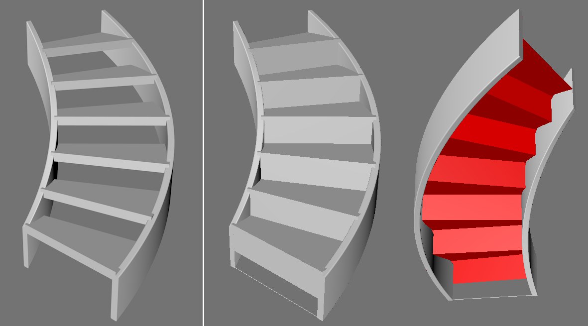 Steps can be generated as separate tread surfaces (at left) or as a closed construction (at right). For the latter the steps will not be given a volume and are colored red on the underside. A separate plane with a Bottom option enabled can be activated beneath the steps to close the staircase when viewed from the bottom.
The staircase can be a free floating or massive construction. Enabling or disabling the Risers option in the Main Settings menu switches between these two types of construction. If disabled, each step’s height can be adjusted using the Step Height (Disable Risers) value. Otherwise the front and back sides of each step will be connected with the neighboring step. The steps will be a single object without any wall thickness. This can be seen when viewing the staircase from below - the back side of the surfaces will be colored red. To close the staircase on the underside and make it look like a massive construction, enable the Bottom option in the Bottom Cap (Enable Risers) menu.
This menu’s Rotation Offset value can be used to rotate the bottom plane, including the staircase’s stringer and the inner rails around the staircase’s rotational axis. As a rule, however, this value should remain at 0° to ensure that the tread surfaces are covered completely when the staircase is viewed from below.
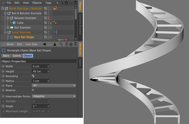 The stairs’ stringer are defined using a rectangular spline in the default settings. This spline’s size and rounding can be adjusted directly in the hierarchy.
The steps are bordered by a rectangular stringer whose cross-section is defined by the Base Rail Shape Rectangle spline, which is located in the Object Manager below the Rail & Baluster Example Null object’s hierarchy as a Child object of the Rail Example object. This spline’s size and Rounding can be edited to modify the look of the stringer. This spline is positioned automatically at the left and right edge of the staircase. Its position can be offset vertically or horizontally using the Vertical Offset and Horizontal Offset values located in the Base Rail menu’s Inner Base Rail and Outer Base Rail sub-menus, i.e., separately for the inner and outer borders of the staircase. The Base Rail options can be disabled individually if you want to omit one of the rails.
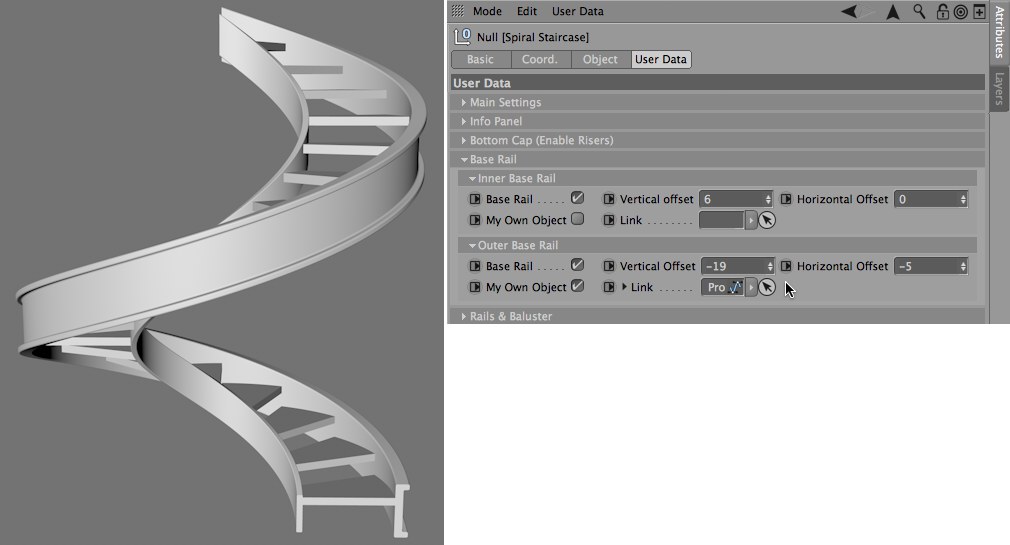 The stringers can be omitted entirely or replaced altogether by a custom spline. In the example above, a custom spline was used to create the stringer.
It is also possible to use a custom spline to create the stringer. To do so, activate the My Own Object option in addition to the active Base Rail option and place the custom spline in the Link field. The custom spline should lie on the XY plane of its coordinate system. Different shapes can be assigned to the Inner Base Rail and Outer Base Rail elements.
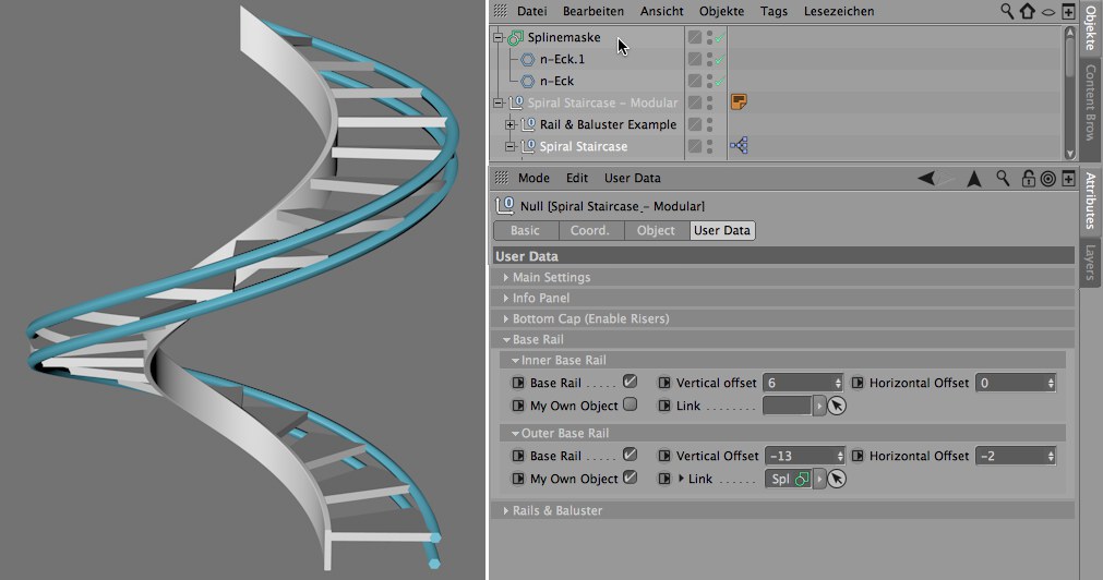 If you want to create more complex stringers, multiple splines can be combined with a spline mask or a Connect object and then placed into the Inner/Outer Base Rail’s Link field. In the example above, two n-Side splines were combined with a spline mask, after which the spline mask was placed in the Outer Base Rail’s Link field.
The outer and inner railing can be configured separately. The settings are identical and can be found in the Rails & Baluster menu.
The railing’s shape must be defined by a spline that lies on the XY plane of its coordinate system. The spiral staircase’s default configuration already contains two Circle splines, which are located in the Rail & Baluster Example Null object’s hierarchy. Different splines can be combined to create rails that are made up of multiple elements that are arranged parallel to the staircase. You can also use a single spline object and assign it to both the Inner Rail an Outer Rail fields. The railing’s height above and lateral distance from the steps is defined using the Rail Vertical Offset and Horizontal Offset settings, respectively, for the inner and outer railings. The Inner Rail and Outer Rail fields can be left empty if you want to omit one or both railings for the staircase.
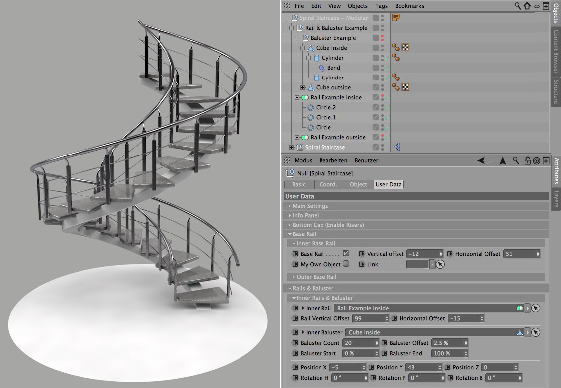 Designer railings can be easily created by using custom splines for the railing and custom polygon objects for the balusters.
Attaching the railing to the staircase
The staircase’s default configuration uses cubes to attach the railing to the stringer. This cube is located in the Rail & Baluster Example Null object’s hierarchy in the Object Manager as a Child object of the Baluster Example Null object. This link can be re-directed to a custom object, if desired. You can also link to object groups - simply link the top object in the group as a baluster. The Inner Baluster or Outer Baluster fields can be left empty if you want to omit one or both balusters from the staircase.
The number of balusters for the railing is defined by the Baluster Count value, which can be defined separately for the inner and outer sides. The elements will be arranged between the Baluster Start and Baluster End values, whereby these percentage values refer to the overall length of the staircase. A Baluster Start value of 0% in combination with a Baluster End value of 50% will arrange the elements uniformly along half of the staircase’s overall length. The first element will lie exactly at the position defined by the Baluster Start value. At the end, a gap will lie between the last element and the end of the staircase or the position defined by the Baluster End value. The Baluster Offset value can be used to move the elements along the staircase to close the gap for the first and last element, or to adjust the Baluster Start and Baluster End positions individually.
The Position X, Position Y and Position Z settings can be used to correct the position of the elements relative to the default position. The Rotation H, Rotation P and Rotation B settings can be used to rotate the elements around their individual object axes.