Fold My Design!
Fold My Design! – create unique stencils for 3D shapes
Among other things, a stencil reproduces the contours, cut-outs and fold seams of a folding box. These paths can, for example, be created using illustration programs such as Adobe Illustrator or using Cinema 4D’s own Spline tools. When the stencil is cut out along the contours and folded along the fold seams, a three-dimensional packaging can be produced. The Fold My Design! feature minimizes the work required to create a 3D packaging from a 2D stencil - and even makes it possible for you to animate the folding process!
Preparing the 3D reconstruction
If a stencil is created in an illustration program make sure that all segments are closed prior to export. Save the scene in Illustrator 8 format. Cinema 4D is able to open these files directly using the File / Open Project command. The paths will appear as separate Spline objects in the Object Manager.
These types of paths can also be created directly in Cinema 4D. In any case you should make sure that the splines’ axes are centered and oriented uniformly. To do so you can select all splines and then use the Mesh / Axis / Center Axis to command. The splines should also lie on the world coordinate system’s XZ plane. Fold My Design! can also correct this itself, if desired, but it’s a good idea to check this yourself upon import or when creating Spline objects in Cinema 4D.
Calling up the Fold My Design! feature
Open the Content Browser by clicking on its tab at the right of the Object Manager in the Standard layout or using the
Double-click on it so it opens in your current scene.
The Fold My Design! object only consists of several Null objects. Two Annotation tags are attached that contain instructions for using this feature. Selecting the Fold My Design! object will open a HUD display in the active viewport and will also make numerous options available in the Attribute Manager with which the type of folding and its animation can be defined. More about this later. First, arrange the existing Spline objects under the stencil beneath the Splines object, which is located beneath the Fold My Designs! object.
 The stencil’s individual splines must be grouped in the Fold My Design! object’s splines group. The order of the splines in this group and the Fold My Design! object’s Mode Index settings define the order in which the folding will take place.
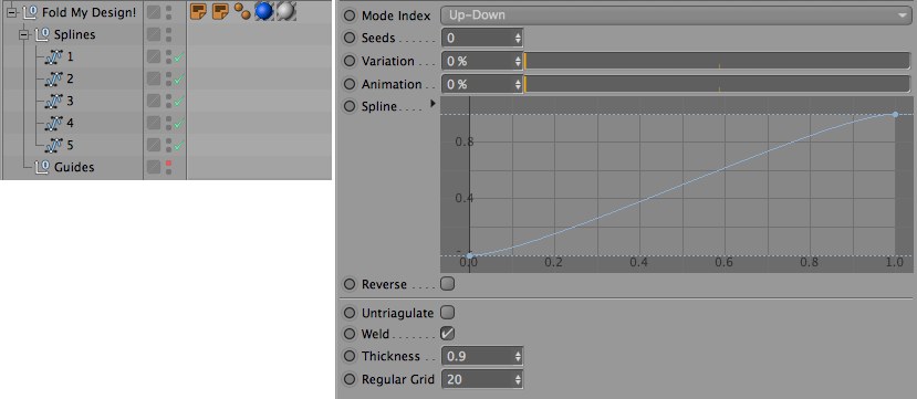
The order in which the stencil splines are arranged in the splines group is important. They will be processed from top to bottom by default. This means that the first spline in the group will not move because it serves as a basis for the other surfaces and flaps. A different order can be defined in the Fold My Design! object’s Mode Index settings. Down-Up will use the last spline beneath the Spline object as a basis for the folding process. If Random is selected, a random surface will be selected to serve as the basis for the folding process. This will also produce a random order for the animated folding. The Seeds value defines the randomness. However, a certain amount of variation can also be added to the otherwise strictly sequential Up-Down and Down-Up modes. To do so, use the Variation slider, which can also be found in the Fold My Design! object’s User Data menu. The folding process will then always take place in the order of the grouped splines and higher Variation values can also result in deviation in timing for some elements. This makes the folding process look less mechanical.
After the Spline objects have been placed beneath the Fold My Design! group’s Null object and their order arranged as desired, check the position and orientation of the objects’ axis systems. The axis systems should be uniform and centered. If this was already checked upon import or when the Spline objects were created in Cinema 4D, another check won’t be necessary. Otherwise the Fold My Design! object offers its own Center & Rotate Spline function in its Tools menu. This function can also be found in the HUD of the active viewport if the Fold My Design! object is selected.
As soon as this option is enabled, the splines’ object axes in the group will be oriented uniformly and centered on the spline shapes. This option will subsequently disable itself automatically.
Next, activate the Fold Preview option. This option can also be found both in the HUD as well as in the Tools menu. Abbreviations and numbers will be displayed in the viewports that show the order in which the stencil’s surfaces will be folded. Your Spline objects will be assigned corresponding names as numbers in the Object Manager. The number’s size can be adjusted to fit the stencil’s size using the Preview Text Size setting - either directly in the Fold My Design! object’s dialog or in the HUD display.
The base surface will additionally be assigned the abbreviation B. This information can, for example, be used to correct the order of the Spline objects. The Spline objects are also color-coded.
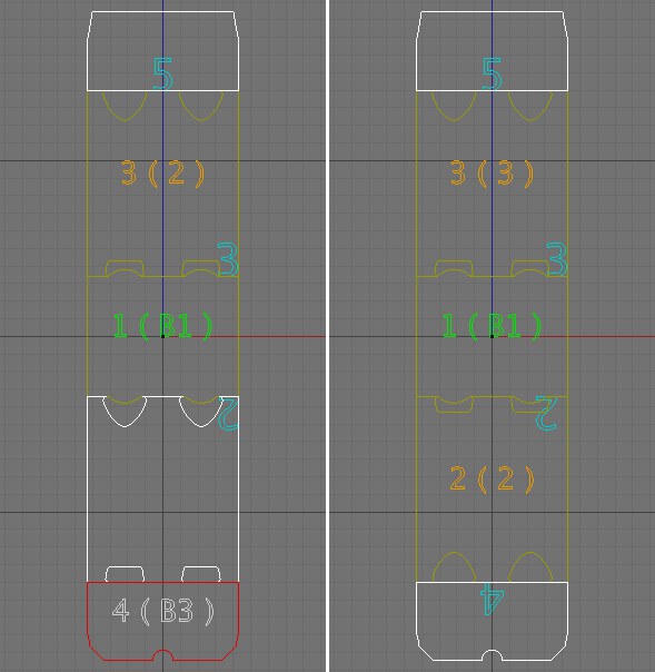 If Fold Preview is enabled, the splines will be differentiated by colors and numbers. White surfaces represent flaps and glued surfaces at the stencil’s edges. If the wrong surfaces are colored white, the vertex positions in relation to neighboring splines must be checked. Red surfaces are generally not matched perfectly to neighboring surfaces. Here the vertices must also be checked or re-positioned, if necessary. The corrected result is at the right of the image.
These will first be visible once the Fold My Design! object is no longer selected. Three color variations are possible:
Dark yellow highlights sections of the stencil that lie between other surfaces. This color is a good sign because it means that connections to neighboring splines have been found.
White splines highlight a stencil’s end sections, e.g., flaps. This also means that another spline was found on at least one side of the flap that is connected to this flap. If this shape is an intermediate section of the stencil, the white color means that at lease one connection to a neighboring spline was found. This can occur if a spline’s points do no lie exactly on top of each other. In this case, use the Snap to Point function to arrange the points accordingly. Another option would be to add new points to neighboring splines at the same location. The Plane Cut tool is particularly well suited for this task (
Click and drag a short line over the splines’ common segment. After the mouse button is released, an identical point will be created for both splines. If a spline is colored red, no connection to other parts of the stencil were made. In this case you must also use the Snapping function to add new points at the same location. Do not proceed until all splines have a dark yellow or a white color.
In the Fold My Design! object’s HUD, click on Create Guides to start the calculation of the stencil’s assembly. This option can also be found in the Fold My Design! object’s Tools menu in the Attribute Manager. This option will create several helper objects that can subsequently be found in the Guides group in the Object Manager. These are mainly rotational axes and invisible controllers that can be used to modify the surfaces individually. This can be useful, for example, if a glued flap must lie at a specific distance from a surface or if the packaged product pushes the walls of the packaging outward. These surfaces represent the packaging’s material and therefore also have a thickness, which can be adjusted using the Threshold value in the Fold My Design! object’s User Data menu.
 After clicking on Create Guides, surfaces will appear within the stencil and a material thickness will be simulated. The Animation slider can be used to show the default folding process at 90° for each flap.
Here you will also find the Regular Grid value, which can be used to create additional points within the stencil. These points will be arranged in a uniform grid whose spacing is defined using this value. Smaller values will create more points within the stencil surface and make it possible to later shape it more organically, e.g., if the packaged product pushes the packaging’s walls outwards.
This uniform point grid’s corner points must be connected with the splines’ points at the stencil’s edge regions. The interpolation and the number of Intermediate Points on the splines should be adjusted accordingly in order to create a connection that is as harmonious as possible. To do so, select all splines in the Splines group and use the Intermediate Points menu’s Number setting in the Attribute Manager. This setting lets you adjust the density of the points in both curves (via the Angle setting) as well as on linear sections (via the Maximum Length value). The goal is that the regions of the uniform grid pass over the stencil’s edge regions as fluidly as possible. The Wireframe mode is the best mode in which to check your work.
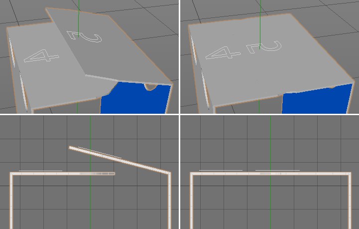
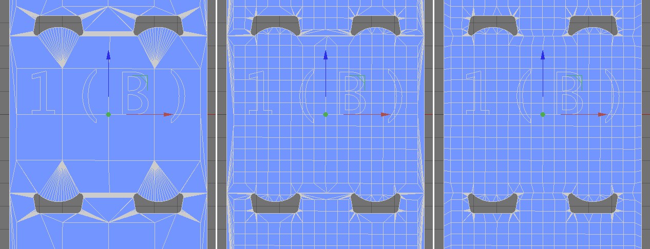 The original stencil is at the left after the guides were activated. The surface density within the stencil can be increased via the Regular Grid setting (at center). After the intermediate points have been adapted to the stencil’s splines, the edge regions are also subdivided to match the grid spacing of the inner surfaces (at right).
Existing structures can be further optimized by combining multiple triangles to quads. To do so, enable the Untriangulate option in the Fold My Design! object’s User Data menu. The Weld option will weld double points that lie at the edges of neighboring stencil surfaces to a single point. This improves the display quality of the material thickness when the packaging is folded. Increasing the Animation value in the User Data menu will fold the splines according to their defined order. This function is also available in the HUD. If Animation is set to 100%, the packaging will be completely folded. This function can be inverted by enabling the Reverse option in the User Data menu. Moving the Animation slider between 0% and 100% will fold and unfold the packaging accordingly.
The order of the folding process is defined by the order of the Spline objects in the Splines group. Temporal variations can be added to make the folding process look more dynamic and less mechanical. Use the Variation value in the Fold My Design! object’s User Data menu to do so. Lower Variation values will produce a correspondingly more linear behavior. For example, the 3rd spline will not move until the second has reached its final position. The calculation of the Variation setting is based on the Seeds value. If this value is change, the random order of the folding process will also be affected.
The Spline curve below the Animation setting in the User Data menu shows the speed with which the folding process takes place. Consider the function graph’s horizontal axis as linked with the Animation value. The Animation value of 0% is represented by the left end of the graph and the maximum value is represented by the right end of the graph. The curve’s height shows the strength of the fold. When the curve reaches a value of 1.0 at its right end, the fold is complete. Hence, the curve should generally run from the bottom left to the top right of the graph. The curve can, however, be used to adjust the speed of the fold. This works best when the Animation value is animated linearly. Otherwise the interpolation of the keyframes will overlap with the Fold My Design! object’s Spline curve and make the timing of the folding less predictable.
 Each surface can rotate around an individual axis when folded. These rotation settings can be found in the guide splines’ User Data menu.
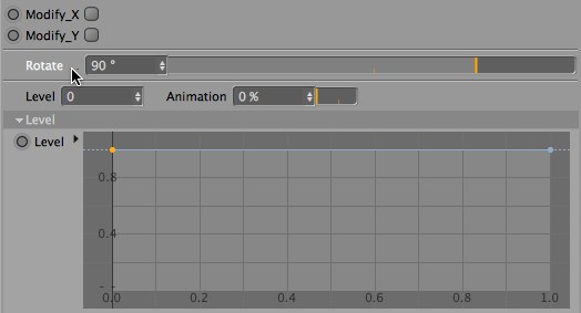
The degree to which each surface should rotate can be defined individually in the splines’ User Data menu, which is located in the Guide Null object’s menu. Here you will find, among others, an Rotate setting that is set to 90° by default. Simply modify this value accordingly if you want to assign a different final position. As already mentioned, the base surface will not be rotated during the fold animation. This is why the corresponding setting is not available for that Spline object.
Note the model’s colors when defining the Rotate value. Blue surfaces are those that lie on the inside of the package when folded. Gray surfaces are the outer surfaces of the packaging. Hence, if your base surface represents the top surfaces and not the floor, simply rotate the Fold My Design! object 180° around its Z axis.
 Glued flaps may have to maintain a certain distance from the neighboring surfaces to prevent them from penetrating during the folding process. The image above is an example of such a case. In the left column you can see the packaging shortly before the folding process is complete. In the right column you can see two views of the folded package. The right flap does not lie correctly on the opposite surface.
Adjusting tuck-in and glued flaps
In many cases you will already have a completed packaging after the Rotate angle has been defined and the Animation slider has been set to 100%. If this is the case you can simply load an image of your printed stencil into the OUT material’s Color channel and you’re done. Note, however, that this image must fit the shape and size of the original stencil as precisely as possible so the 3D model of the packaging is filled out to all edges.
However, if this is a packaging that is squashed or stretched by the product in side or by the manner in which it is glued, additional steps will be required. Numerous settings are available for this purpose in the Fold My Design! object’s Guides group.
In many cases the stencil will contain surfaces that will be glued. These surfaces should, of course, not penetrate or sink into other surfaces - they should lie on top of the surface(s) to which they are glued. You will find a Level setting in the selected Guide spline’s User Data menu. Note that this setting is not available for your stencil’s base surface.
 After enabling the Level function and adjusting the Level splines, the glued flap will fold correctly and come to rest on the surface to which it should be glued.
Level values can only be positive values and move the corresponding surface outwards, i.e., in the direction of the stencil’s printed side. This movement can be fine-tuned using the special Level curve below the setting. The graph’s horizontal position represents the length of the flap. By modifying the curve you can define which end of the flap should be raised. The curve should, however, have a value of 0 at the left or right end to maintain a connection with the neighboring surface.
If you want to use a more complex curve, make sure that the subdivision on the corresponding section of the stencil is adjusted accordingly. Please refer to the Fold My Design! object’s Regular Grid function described above.
Next to the Level setting you will find the Animation slider. This slider is used to define the point at which the Level movement should become visible during the folding animation. If set to 0% or 100%, the Level movement will already lie on the flat stencil and will not change its position throughout the folding process. Intermediate Animation values will have a completely different effect. The larger the value and the nearer it lies to 100%, the later and faster the Level movement will be during the fold animation. A value of 1% will produce a very smooth transition between the flat stencil and the end position defined by the Level value.
If a product is enclosed by its packaging it can cause the packaging’s sides to bulge. The packaging adapts its shape to that of its contents. Contrary to the Level function, the continuity between neighboring surfaces should not be interrupted. There are different ways to create such deformations:
Using modification curves for deformations
In the Fold My Design! object’s Guides’ menu you will see the Modify_X and Modify_Y options. Enabling these options will add the suffixes MX and MY, respectively, to splines that are added beneath the respective Guide spline. These are deformation splines that can be edited directly in Use Point mode. However, before you begin editing you should consider how many points you actually need along this deformation spline. If an MX or MY object has been selected, its user data will be displayed in the Attribute Manager. The Num value defines the number of points on the respective spline. The more points you use, the more detailed the surface’s deformation will be. Of course, this is also dependent on the stencil’s polygon density. Note that modifying the Num value will undo the previous deformation.
Enabling the Reset option will reset the spline shape. All previous deformations will be deleted.
The MX and MY splines also offer an Anim slider in their User Data menu, which can be used to define the point at which the deformation will take effect. If 0% or 100% are used, the full deformation will be visible on the flat stencil. Values near 0% will produce a very smooth fold animation. Higher values will delay the deformation accordingly - up to the point of it taking effect in the very last moment.
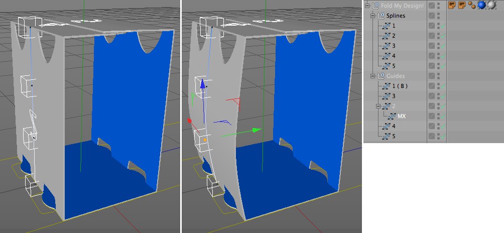 Using the modification curves MX and MY you can deform individual stencil surfaces to make them adapt their shape even better to the contents of the package.
If you want to concentrate on the shape of a packaging’s individual sides the remaining sides of the stencil can be hidden by selecting the Guide spline you want to edit and activating the Solo option in the HUD or in the Fold My Design! object’s settings. Disable the Solo option to display all sides of the packaging.
The Modify_X and Modify_Y options make it possible to intuitively reshape parts of the packaging using splines. If you don’t need this direct type of reshaping, a similar result can be achieved by using the Position X and Position Z settings in the Guides’ User Data menu. These settings let you distort each surface of the flat stencil in X, Y or Z direction. A surface can be skewed, scaled or bent. The first value for the Position X vector moves the points of the selected section along the stencil spline’s X axis. The first value for the Position Z vector does the same along the spline’s Z axis. The third position vector works similarly. The last Position X value extends or shortens the section along the spline’s Z axis. The Third Position Z value affects the size of the section along the spline’s X axis. Which sections are affected to which degree is defined using the Spline XZ curve, which can be found in the Position menu below these settings. The curve’s height represents the strength of the deformation at the respective location on the packaging.
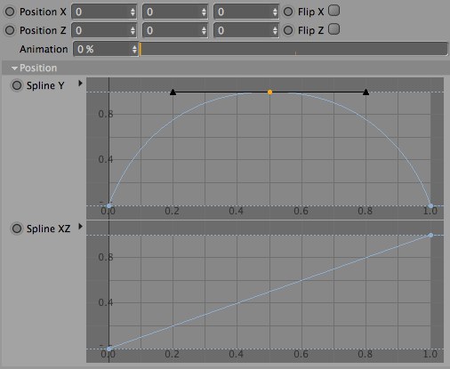 Stencil surfaces can also be bent and distorted individually using the position vectors and the spline graph.
The second Position vector values move the points parallel to the spline’s X and Z axis, perpendicular to the packaging’s plane and inwards or outwards, which produces a bulging surface. The shape of these bulges can be defined using the Spline Y curve, which is located below these settings. The Flip X and Flip Z options can be enabled to reverse the bulge without having to readjust the shape itself.
As already explained, the packaging shape can be linked to the Animation setting, which is used to fold the stencil. This Animation setting is located beneath the respective Position X and Position Z settings. If set to 0% or 100%, the deformation will be present at its full strength during the entire fold animation.
If small values such as 1% are used, the deformation will be introduced very smoothly into the fold animation as it progresses. Higher values will result in the deformation being introduced correspondingly later in the animation, which also results in the effect taking place correspondingly faster.
Adjusting the rotation of packaging sections
The same principle as described above can also be applied to the Rotation X and Rotation Z settings. The only difference is that only a single Rotation curve is used to control the rotation along the axes. Here you will also find the Flip X and Flip Z options to reverse the respective rotations.
The Animation slider defines the point at which the stencil’s segment should begin to rotate. Higher values will cause the rotation to begin correspondingly late in the fold animation and small values will produce a smooth transition between the stencil’s initial state and the final state. If Animation is set to 0% or 100%, the rotated shape will already appear at the beginning of the fold animation.
Try to keep deformations to a minimum because the packaging’s printed surface will also be distorted. Text and logos may be stretched or squashed.
 If you only need the packaging as a model, the Make Editable option can be used. This will make it possible to edit the model using the normal polygon tools.
Using Fold My Design! for modeling
If you only want to use the folded packaging for a still image or animation you can configure the packaging and complete the animation, after which you can use the Make Editable option in the Fold My Design! object’s Tools menu to make the object polygonal. The splines will be maintained and you will also have a mesh object, i.e., a normal polygon object, in the shape of the packaging.
This object also contains all necessary selection tags required for assigning materials to the front or back sides, or to the sides of the folded packaging.
Making the Fold My Design! object editable bears the advantage that it can easily be exported to other applications or edited using the Cinema 4D polygon tools.
Please note that animations created using the Fold My Design! feature currently cannot be rendered using Team Render.