XPresso Editor
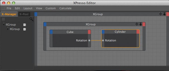
To create a new expression and open the XPresso Editor, in the Object Manager, select any object and choose Tags / Programming Tags / XPresso. You can close the editor at any time and reopen it by double-clicking the XPresso Expression tag.
Nodes are the building blocks of your XPresso Expressions. Nodes can perform a wide variety of tasks, from reporting the animation’s current frame number to setting an object to a particular position. To build your expression, you create the necessary nodes and connect them to one another by drawing lines, called wires, between the node input and output ports. The nodes are then able to pass values to one another via these ports and wires.
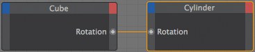
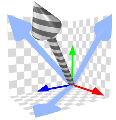
The illustration above shows two nodes: one for a cube and another for a cylinder. the two circles, both labeled Rotation, are ports. The ports under the red squares are output ports and send values to XGroups or other nodes. The ports under the blue squares are input ports and receive values from other nodes or XGroups. In this example, the cube’s rotation value is being sent to the cylinder. This will cause the cylinder to point in the same direction as the cube in the viewport.
To learn XPresso as quickly as possible, we recommend that you work through the tutorials in the Cinema 4D Tutorial manual and, if something is not clear, look it up in this reference for a full description. In addition, you will also find a variety of example expressions on your Cinema 4D CD, each documented with comments. Much can be learnt from these examples by reading the comments and then trying out your own changes.
XGroups are containers for nodes, other XGroups and their wires. Like real containers, XGroups help you to put related items in the same box for better organization. You will then find it easier to understand, navigate and modify the expression. In addition to acting as a container, an XGroup can be connected to nodes and other XGroups. You can save and load XGroups to reuse them in other projects.
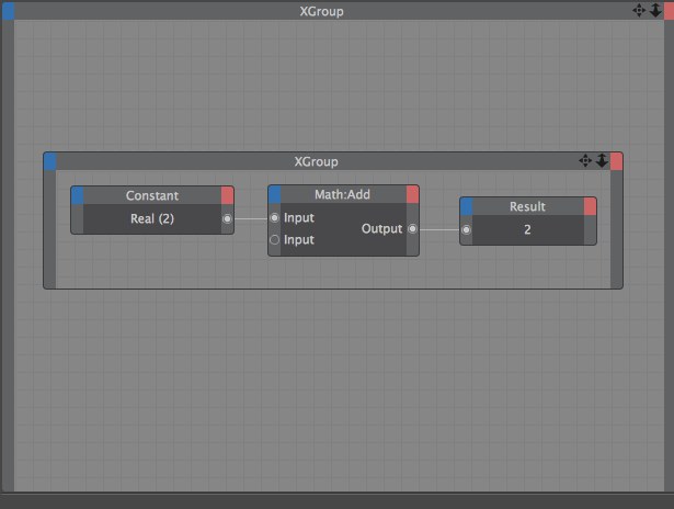 Use XGroups to organize nodes into groups.
You can navigate the contents of an XGroup in a similar way to the Cinema 4D viewport. To move or zoom the contents, drag the move or zoom icon in the top right corner of the XGroup. You can also move the contents by pressing the cursor keys. To add ports to the XGroup, choose the desired ports from the XGroup’s inputs menu (blue square) and outputs menu (red square).
To minimize an XGroup to its title bar, double-click the title bar. To restore an XGroup window to full size, double-click the title bar again. To move an XGroup, drag its title bar. To re-size an XGroup, drag a side or corner.
When creating your own expressions, you will often need to select an XGroup to, among other things, load its settings into the Attribute Manager so that you can edit them. To select an XGroup, click the XGroup’s title bar. To select multiple XGroups, drag a marquee over them, or select one of the XGroups then Shift+click the other XGroups that you want to select; selected XGroups have orange borders.
On the Attribute Manager’s Node Properties page, you will find an option called Inputs First. If this option is enabled, nodes that are outside the selected XGroup are evaluated first. This is especially important when the XGroup receives values from the nodes, to ensure that the XGroup receives up-to-date values.
Double-clicking on the XGroup window’s title bar will reduce the window to the title bar. Double-click again to restore the window. Clicking and holding on the title bar will let you drag the XGroup window and clicking and holding on the XGroup window’s frame (the cursor will change to a scale symbol) will let you scale the window. A simple click on the XGroup window’s title bar will select the XGroup, e.g., for copying and pasting or to access the settings and data types in the Attribute Manager. Multiple XGroups or nodes can be selected by
This option allows you to switch the XGroup on (active) or off. The nodes inside the XGroup will only be processed if the XGroup is active. You can also switch the node on by passing a Boolean value of True or the value 1 to its Enable port.
You can password protect XGroups using this button, which will hide the contents of the XGroup until the password is entered.
To protect an XGroup, first choose View / Locked to lock the XGroup’s contents. In the Attribute Manager, click on the Protect button. In the dialog that opens, enter your password for the XGroup. The XGroup will now be password protected.
To unprotect an XGroup, you do almost the same as you did to protect it, except in reverse. First, click on the Unprotect button and enter your password into the dialog that appears. To reveal the contents of the XGroup, disable View / Locked from the context menu and choose the desired display mode from the context menu’s View sub-menu.
Nodes are the primary building blocks of expressions and are designed to carry out the most diverse of tasks, from reporting an object’s current position to processing math operations. Depending on the node’s type, you can add various inputs and outputs to the node called ports. As with XGroups, you add these ports using the inputs menu and outputs menu (the blue and red squares respectively in the node’s title bar).
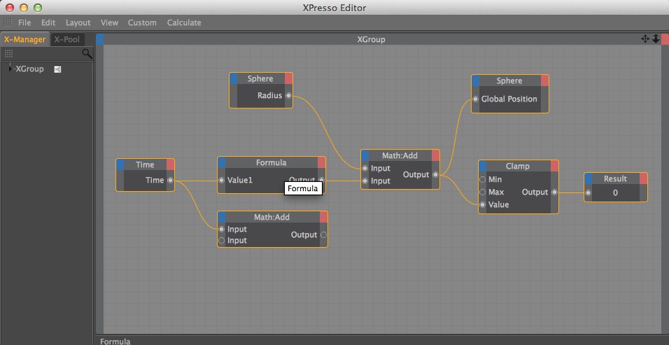
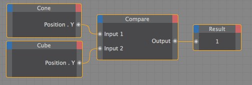 Four nodes. The Result node shows the value 1 if the cone and cube are at the same height (Y value).
You can minimize or maximize a node by double-clicking its title bar; to move a node, drag its title bar; to re-size a node, drag a side or corner. Click a node to select it and load its settings into the Attribute Manager. To select multiple nodes, drag a marquee over them or select one of the nodes then Shift-click the other nodes that you want to select; selected nodes have orange borders.
You can switch nodes on or off via the Enabled option in the Attribute Manager or the Disable option from the node’s context menu, which is described later in this chapter.
To rename a node, select the node and enter its new name on the Attribute Manager’s Basic Properties page. The default name of a node indicates its type. If you rename a node, you can check its type in the Attribute Manager. You can also set the node’s data type in the Attribute Manager; this defines what type of data the node handles, such as integers or strings.
You can reassign an Object, Material or tag node to a different object, material or tag. Simply drag and drop the object, material or tag onto the inner part of the node (i.e. into the area where the port names usually appear). The original ports will be preserved if still appropriate for the new object, material or tag. Ports that cannot be preserved will be set to the undefined status.
Each XPresso node is described later in this chapter.
Ports are the inputs and outputs of nodes and XGroups. To add a port, choose the desired port from the inputs menu (blue square) or outputs menu (red square); in these menus, ports that have already been added are ghosted.
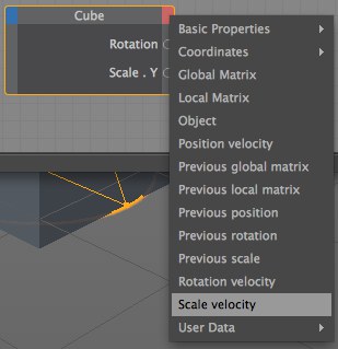 Add ports using the inputs and outputs menus (the blue and red squares in the node’s top corners).
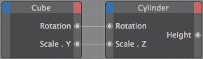 Values are passed via ports. Output ports are under the red and Input port are under the blue squares.
Red ports are output ports and send values to other nodes or XGroups. Blue ports are input ports and receive values from other nodes or XGroups. To connect an output port to an input port, drag and drop the circle of one port onto the other. A wire will connect the ports, as illustrated below.
Various commands that are specific to ports are available from the port’s context menu.
If a node or XGroup is selected and has unconnected ports, these are shown on the Attribute Manager’s Parameter page (does not apply to Object nodes); you can send values to these ports by entering values on this page. This can be especially useful for testing nodes with particular values. The Attribute Manager also enables you to send your own data to nodes (see User Data, below).
To display a port’s name, hover the mouse pointer over the port and its name will appear in the XPresso Editor’s status bar. (To switch on the status bar, enable the Show Status Bar option on the XPresso Editor’s Layout menu). To display port names, enable the Ports / Show Names option on the context menu.
Double-clicking on a port will disconnect it. If the port is already disconnected, double-clicking on the port will delete it instead. To change a port’s vertical order, Alt+drag the port and drop it in its new position.
Ports defined for element parameters can also be marked in the Attribute Manager:
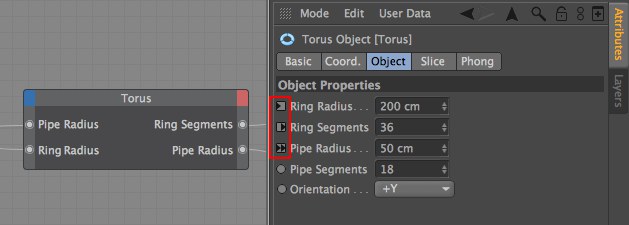
- Active XPresso Input ports: Triangle left
- Active XPresso Output ports: Triangle right
- Active XPresso Input and Output ports: Double triangle
- No port: Circle will be displayed
User Data ports enable you to send your own values to nodes via the Attribute Manager.
To create a User Data port
- In the Object Manager, select the object to which the port should be added. Only user data added to objects in the Object Manager can be used in the XPresso Editor. User Data added to XGroups cannot be used in the XPresso editor.
- In the Attribute Manager, choose User Data / Add User Data. In the dialog that opens, set the port’s parameters as desired, then click OK.
- Click the node’s inputs menu (the blue square) and choose the name of the User Data port.
- You will now be able to send values to the port via the User Data parameter on the Attribute Manager’s User Data page. See the XPresso tutorial in the Cinema 4D Tutorial manual for a working example of why user data is useful.
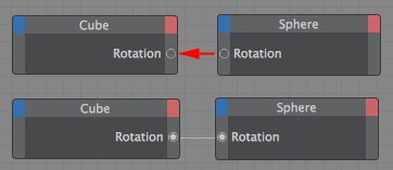
 Wires enable you to connect the ports of nodes and XGroups.
To enable nodes and XGroups to pass values to one another, you must first create the necessary ports and connect those ports using wires. To create a wire between two ports, drag the circle of one port and drop it onto the other. A line appears while you drag that snaps to the second port when the mouse pointer is close to it.
Some connections are not allowed. For example, you cannot connect input ports together or output ports together, nor can you connect ports that have incompatible data types. While you draw the wire, its color changes to indicate whether the connection is allowed (green) or not allowed (dark grey). If the connection is not allowed, the wire will be deleted as soon as you release the mouse button.
An output port may be connected to multiple input ports, thus enabling you to pass the same value to several nodes or XGroups. However, an input port may have one connection only.
To connect an output port to an input port of the same node, copy the node (hold down
If you accidentally connect a wire to the wrong port, you can reconnect it by dragging and dropping the wire onto the correct port. If you drop the wire onto an empty space (i.e. not onto a port), the wire will be deleted as soon as you release the mouse button. You can also delete wires by choosing Remove Wires from the port’s context menu.
If the wires in an expression are tangled, reposition the ports by Alt-dragging each port to a new position. You can reposition vertically only. You cannot, for example, Alt-drag an input port from the node’s left edge to the right edge.
Wires will convert compatible data types automatically. For example, if you pass a real value, such as 72.163, to a node that works with integers only, the connecting wire will convert the real value to an integer automatically — in this case, to 72.
Each node and XGroup has a data type that defines the type of value it uses, such as Integer, Vector or Color. If you connect two nodes that use different data types, the wire between the nodes converts the data type automatically if the types are compatible. For example, if a Constant node passes a Real value of 3.45 to a Result node whose data type is set to Integer, the value will be converted to an integer automatically — in this case, to 3.
Although some nodes have a fixed data type that cannot be changed, you can change the data type of most nodes in the Attribute Manager.
This data type consists of the color components red, green and blue. The RGB values can also be interpreted as a vector — so the color R:10, G:75, B:0 would equate to the vector (10;75;0). This enables you, for example, to use a color to control an object’s position or rotation vector.
The Link data type contains information on the various elements in a Cinema 4D scene, including information on tags and materials as well as objects. The Link type cannot be converted to other data types. The purpose of the Link data type is to allow you to select a scene element (such as an object, material or tag) for closer examination. For example, you can use the Link data type to add a user data box in the Attribute Manager. You can then assign materials, tags and objects by dragging and dropping them into the box. See also Object, below.
This data type allows you to store a file path. For example, the Sound node uses the Filename data type to store the path of the sound file that you want to load.
This element contains a reference to a texture, i.e. to an image file or shader. This data type is of use only when used with materials, such as within a material channel.
TheLens Glow data type is a container for a complete data set — in this case, all the information required to control lens glow for a light source. This data type cannot be converted to other types.
The Bool data type has two possible states: True or False. These states are represented by the numeric values 1 (True) and 0 (False). Although you can use Bool values in math calculations, keep in mind that the Bool data type is able to hold a value of 0 or 1 only. When you want to combine several Bool values, use Logic nodes.
The Integer data type supports whole numbers (not fractional numbers) that can be negative, zero or positive. Numbers after a decimal point will be ignored; this can lead to inaccurate results if fractions are involved. You can use the Integer data type with all numeric and vector formats.
When converting a vector to an integer or a real, the length of the vector is calculated automatically from the calculation SQRT(V.x*V.x+V.y*V.y+V.z*V.z), where V.x, V.y and V.z are the X, Y and Z components of the vector and SQRT is the square root function. On the other hand, when an integer or a real is converted to a vector, the value is used for the vector’s X, Y and Z components. For example, the real 12.5 is converted to the vector (12.5;12.5;12.5).
Unlike integers, reals can be fractional numbers. A typical example of a real is Pi, i.e. 3.141592654. Use the Real type when complex calculations are involved and you want an accurate result. Reals can be converted to vectors or integers. When a real is converted to an integer, all numbers after the decimal point will be lost (i.e. reals are rounded down when converted to integers).
The Vector data type is important for manipulating positions and rotations in 3D space. Object positions, HPB angles, colors and point coordinates are all stored as vectors. The values are stored in the vector one by one. For example, positions are stored in the order (X position; Y position; Z position) and rotations in the order (H angle; P angle; B angle). In Cinema 4D, a vector always has three components. If you convert a vector to an integer, the length of the vector is converted rather than the individual components. You can also use vectors with matrices.
A normalized vector is a vector of the same direction, but with a length of 1.
A matrix is a group of vectors, such as an object’s global matrix, that contains the object’s position vector and three vectors for each object axis. The axis vectors represent not only the direction of the object, but also its scale (the scale is defined by the length of each axis vector). Therefore the global matrix gives you access to the object’s position, scale and rotation.
The four vectors are stored in the following registers of the global matrix: V0 for the position vector (called the Offset vector); V1 (X axis); V2 (Y axis) and V3 (Z axis). Using these registers, you can read or overwrite any vector, such as V2 for the object’s Y axis.
The Time data type gives you access to the animation’s current time. Keep in mind that this value is affected by the frame rate. For example, if the rate is 25 frames per second, the Time value for frame 24 is one second exactly. The Time data type is especially useful for controlling dynamic processes since it enables you to take an animation’s progress into account. For example, you can make a ball bounce once per second or make an object follow another over a particular period of time. See also Date/Time above.
The String data type is for text and character strings. A string can hold letters, numbers and special characters. For example, you can use the String data type to allow the user to input a name into a text box. In addition, XPresso wires are able to automatically convert numeric sequences in the string to vectors, matrices or other numeric formats. For example, you can pass the string 12;4;5 to a node instead of the vector (12;4;5).
The Object type is a sub-type of Link and is used for object data only. Among other things, this data type gives you access to an object’s global and local matrices. See also Link, above.
The gradient data type consists of a large number of values that represent a gradient. It cannot be converted to other data types. (Although individual colors can be converted to vectors, there is no way to specify the color’s position in the gradient in order to access it).
Using the Include and Exclude lists, lights can be restricted to specific objects. The Include and Exclude lists contain a list of objects. Since this is specifically designed for use with light sources, no conversion is available. Use an object or light instead to read tags, materials or objects, e.g., in a User Data field.
The Priority data type contains the XPriority and its numerical value, plus details on the order of evaluation. This data type is used for the priority port of tags.
The Font data type stores information for a chosen font, including whether it should be used as a TrueType or PostScript font. For example, you can use the Font data type to vary the appearance of a text spline. The Font data type cannot be converted to other types.
In contrast to the Time data type, Date/Time queries your computer’s current system time (in the format hours:minutes:seconds) and system date. For example, you might create a Sun expression that sets a light’s position and color to match the current real time.
With the Spline data type, you draw a spline in the Attribute Manager using a graph. The graph runs from the variable extremes Min X to Max X along the horizontal axis and from Min Y to Max Y along the vertical axis.
The XPresso Pool provides a quick way to add nodes to the XPresso Editor. The XPresso Pool contains all of the Cinema 4D nodes, to which you can add your own pools, where each node is configured to suit your needs. For example, suppose you often need to create a Math node for integer subtraction (Data Type set to Integer and Function set to Subtract). Rather than change these parameters manually each time you need to create such a node, you can add the configured node to the XPressoPool. The next time you need the node, you can drag it from the pool and drop it into the XPresso Editor, already set up for integer subtraction.
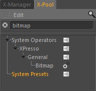
Clicking on the magnifying glass icon will open a text line filter, which can be used to display only the Nodes for which you are searching without displaying all sub-directories.
This is a display filter that works in realtime. All you have to do is enter the text that relates to the Nodes you want displayed. Every element that contains this text in part or in whole will be displayed. Capitalization does not affect the results. Clicking on the X button will clear the text field.
To open the XPresso Pool:
- The XPresso Pool is integrated into the XPresso Editor by default. However, should you undock and close the pool, you can reopen it by choosing Custom / XPresso Pool in the XPresso Editor. To create a node:
- Drag and drop the node that you want to create from the XPresso Pool into the XPresso Editor. To open and close hierarchies:
- Click the icon to the left of an element’s name. To create your own pool of nodes:
- In the XPresso Pool, create a new pool by choosing Edit / Create Pool. (You cannot add your own nodes to the original pool.)
- Configure the nodes that you want to add to the pool.
- Drag the nodes that you want to add to the pool from the XPresso Editor and drop them into the new XPresso pool.
Choose this command to create a new pool for your own node configurations. Use the dialog that opens to define a save path for the pool (note that groups are saved to the Library / xnode folder within the user folder); the pool is saved automatically and will be made available each time you restart Cinema 4D. To add your own node configurations to the pool, first configure the nodes as desired in the XPresso Editor then drag and drop the nodes into the pool.
This command allows you to load a pool file.
Removes the selected preset or folder from the pool.
Renames the preset. For example, if you have configured a Math node for integer subtraction, you may want to rename it to Subtract Int.
Creates a new folder. This enables you to arrange your own pool into folders for better organization. Drag and drop the nodes that you want to place within the folder from the XPresso Pool or XPresso Editor into the folder.