Shader Properties
In each of the following sample images, the AO shader was used in the Luminance channel. Its effect can best be seen here. This is, though, not suitable for photorealistic renderings.
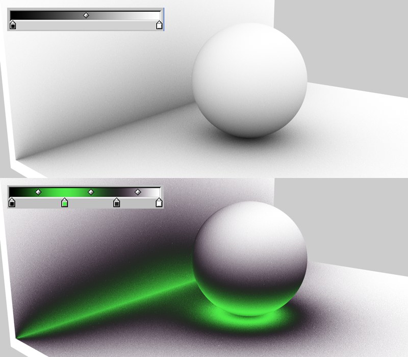
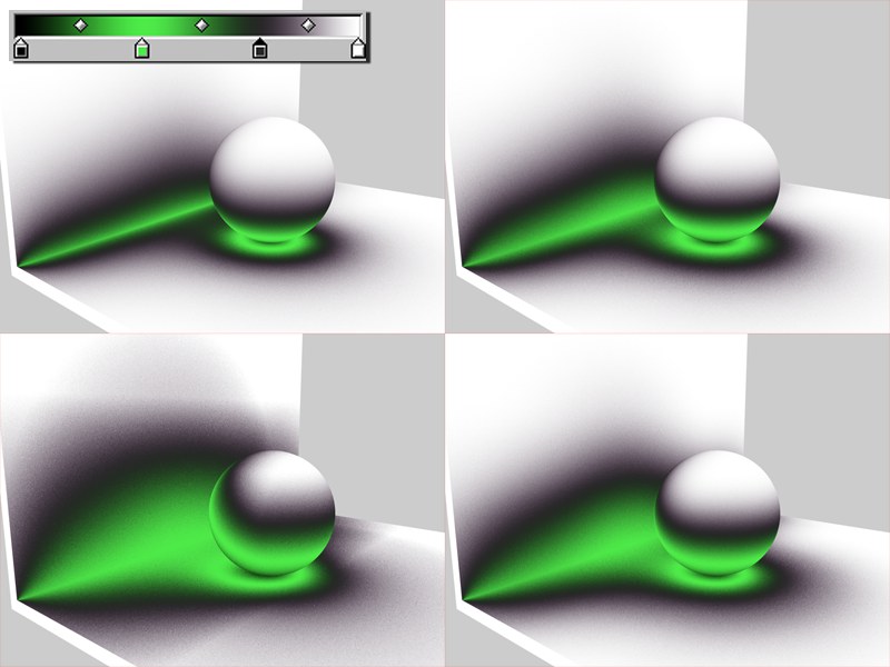
Use the Color option to define the color gradient that AO assigns, dependent on exposure. Normally, it will be a simple custom black to white gradient but other colors can also be defined.
The left end of the gradient represents areas with minimal exposure (bottom of sphere) and the right side represents areas with maximum exposure.
Be aware of the fact that these gradients will be treated as grayscale, depending on the material channel.
Minimum Ray Length determines how the gradient defined in Color will be rendered between exposed and non-exposed areas. The closer the Minimum Ray Length value is to the Maximum Ray Length value, the further the gradient will be pushed towards the edges, which are defined by the maximum ray length.
This value shouldn’t really be tampered with. Leave it set to its default setting of 0.
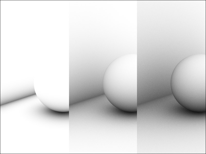 From left to right: increasing Maximum Ray Length values.
This value defines to which distance the surfaces see each other. If low values are used, the wall will not see the sphere and the image is rendered brighter (image: left). Where geometry meets, as with the floor and wall or the sphere and floor, even small rays will fall upon surfaces, which suffices to darken those areas.
If high values are used, a much larger distance will be included within which objects will be able to see each other. This results in a softer, more homogeneous darkening that will cause longer render times (see also sample image at Accuracy setting).
In general, lower values are recommended that offer results as in the left-most example above.
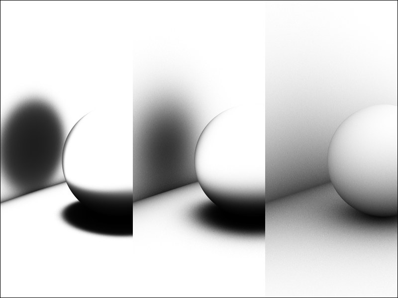 From left to right: Dispersion values of 0%, 50% and 100%.
During each AO calculation, several rays (Samples) will be emitted for each point within a virtual hemisphere in the scene. These samples check to see if any geometry lies within the Maximum Ray Length. Dispersion determines to what extent these samples will be taken into account on the hemisphere’s surface. A value of 0% takes only the hemisphere’s zenith (vertically over the sphere) into account. A value of 100% will take the entire hemisphere into account.
How can this be applied in practice? Imagine Dispersion as blinders. The lower the value, the more the blinders close and the more the sample area will be limited to the vertical.
The image above shows the effects of: Left = 0% – only the areas directly over (perpendicular to) each point have been taken into account. A value of 100%, on the right, takes all of the sphere’s samples into account and produces a realistic result.
The Accuracy, Minimum Samples and Maximum Samples settings are responsible for AO quality. Low quality is accompanied by grainy results. This is not necessarily bad. In fact, in some cases, this may be the desired result since the stochastic result can be of high aesthetic value.
Although, if you prefer homogeneous, seamless transitions, you should select higher quality settings, which will also increase render times.
Use the three previously mentioned settings (especially Accuracy and Maximum Samples) for improved quality.
The basic AO algorithm is complex so we will not go into detail about it here. We will, though, tell you this much: Samples are required to render AO. The more samples that are used, the more homogeneous (less grainy) the rendering will be – the longer the render times will be as well. Fewer samples, on the other hand, result in shorter render times.
Of course a maximum number of samples can be calculated for the entire scene. This would take very, very long to calculate and it does not make any sense since a scene contains many areas in which a relatively small number of samples would suffice.
That’s what the Minimum Samples and Maximum Samples settings are for. Use them to specifically control critical and less critical areas of your scene (and interpolate between them).
The Accuracy setting determines where and in what amount samples must be distributed in order to achieve the best possible result. In critical areas, samples to the amount of Maximum Samples will be used.
Hence, the Accuracy setting has the most influence in critical areas (since higher values in these areas lead to more samples) and less influence in less critical areas, which use the Minimum Samples value.
Example:
The following scene (next image) was rendered with various values for this setting:
- Left column: Maximum samples
- Center column: Accuracy
- Right column: Maximum Ray Length
The relative render times (per column) are noted on each image in order to give you an impression how render time is affected by a change in the settings.
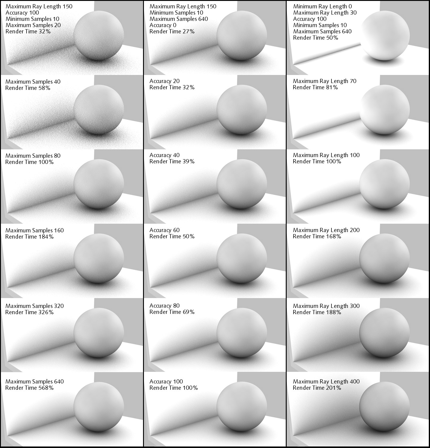 Consistent in all images: Minimum Ray Length 0, Dispersion 100, and Contrast 10.
Use this setting to define the number of samples that should be used in less critical areas.
Use this setting to define the number of samples that should be used in critical areas. The exact number of samples will be dispersed dynamically in correlation to the Accuracy setting.
Use this setting to adjust the AO effect’s contrast. Negative values can also be entered!
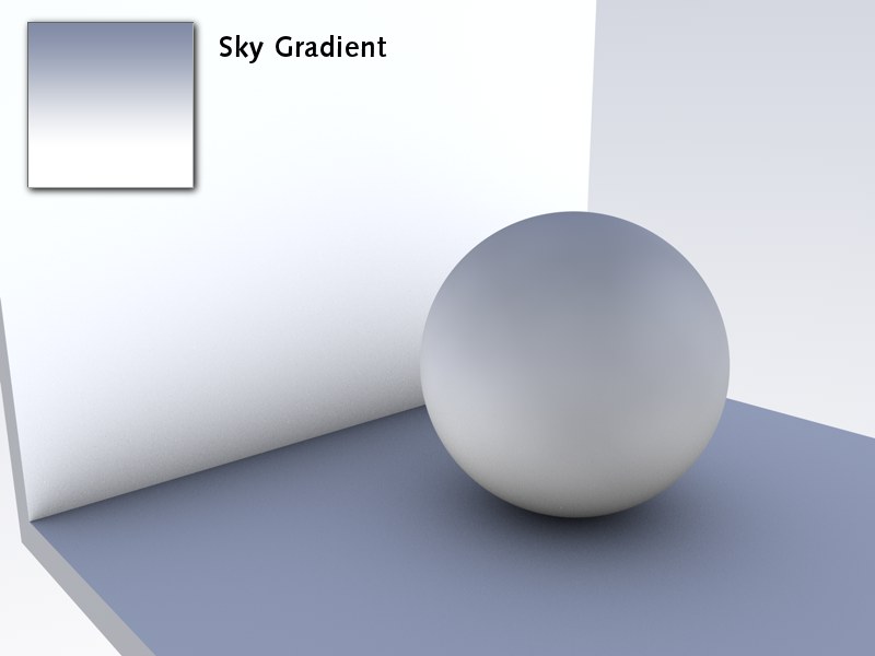 The AO shader in the Environment channel, Use Sky Environment active, no light source.
If AO is used in the Diffusion material channel, a separate light source must be used (even if it’s only the Auto light).
AO also works without a light source if the Sky object is used as Illumination. If Use Sky Environment is active, the reflected sky color will be multiplied onto the final AO image. To do this, AO must be placed into the Environment or Luminance material channels.
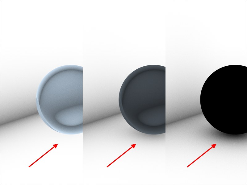 Active Evaluate Transparency option with decreasing transparency from left to right.
When this option is active, transparency will be analyzed on the basis of the Transparency or Alpha material channels. In doing so, the degree of transparency will be taken into consideration: A semi-transparent sphere will still cause some AO in spite of this option being active.
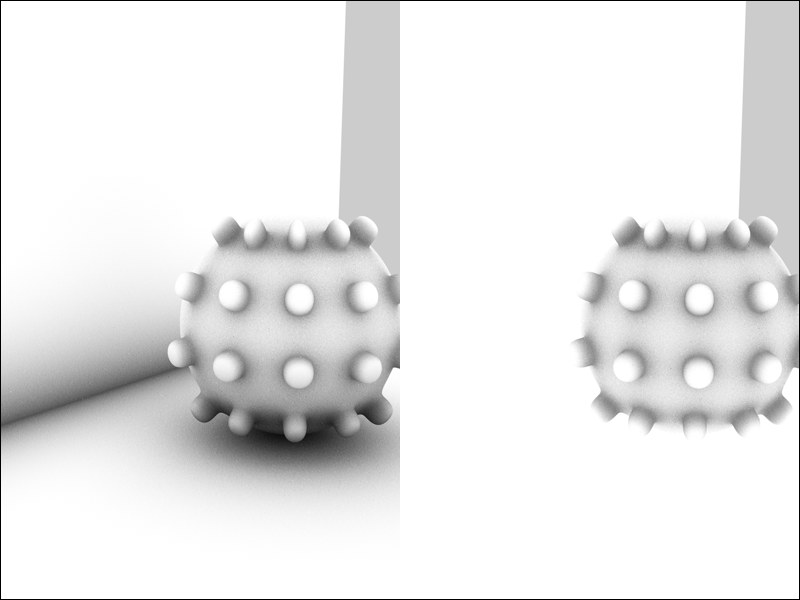 Left: Self Shadowing Only not active. Right: Self Shadowing Only active. Floor and wall are separate objects.
When this option is active, separate objects will not see each other, they will only see themselves.
If this option is enabled, the AO effect will be inverted. Corners and holes will not be ascertained and instead outward pointing edges and corners/peaks will be found. Imagine a sphere around an object: the more surface a point sees of the sphere the darker (default behavior) AO will render this point.
What is this good for?
If exposed surface should, for example, have a different appearance than the remaining surfaces, place the AO shader into the Alpha channel and the respective material will only have an effect on outward pointing edges and corners/peaks:
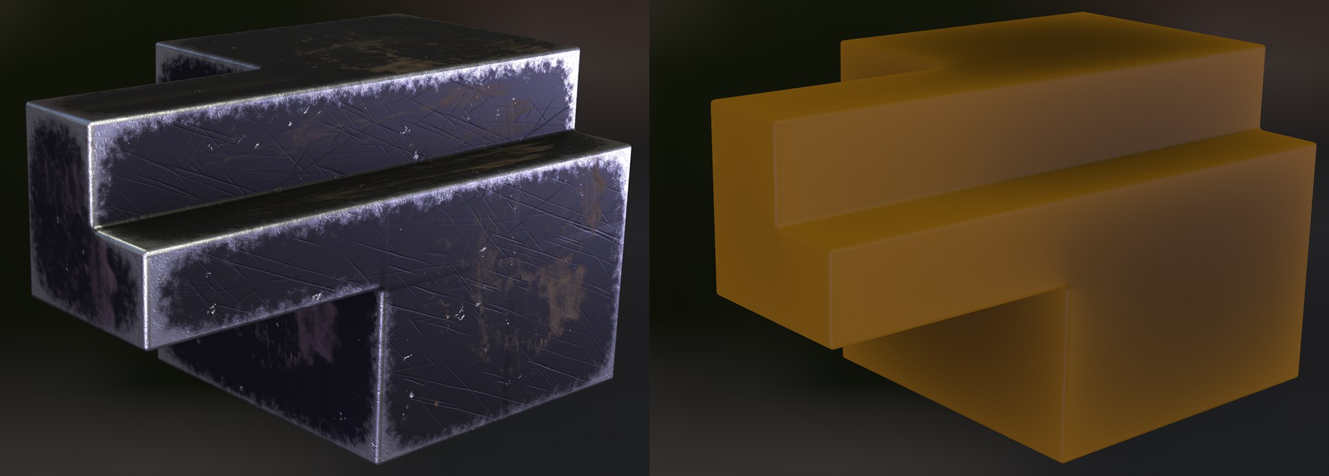 This option can be used to restrict effects to outward pointing edges and corners/peaks.
In the image above you can see surface wear on the left and on the right a quickly rendered Subsurface Scattering imitation on the edges and in the corners.