Table Of Contents
- Introduction
- The Shader Graph Editor UI
- Editing the Shader Graph
- Elements of the Shader Graph
- Color Parameters
- Special Nodes
- Using XPresso Nodes in the Shader Graph
Introduction
The Shader Graph allows you to create and personalize
complex materials inside of Redshift, these materials are composed
of Shader Nodes. The Redshift Shader Graph defines
the structure and the processing flow of the shading
process.
The Shader Graph Editor UI
The Shader Graph Editor is broken up into a couple sections, the Node Tree which includes the Material Preview above, the Shader Graph Area, and the Attribute Manager which includes the Parameter Search box above.
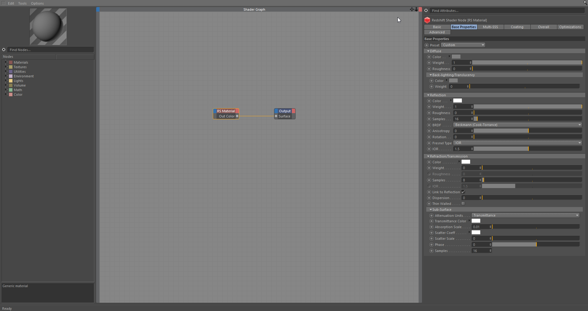
Shader Graph Editor
The Node Tree
The Node Tree located on the far left, contains all the Redshift Shader Nodes that can be added to our Graph Area. The nodes are organized into Categories depending on the type of node or its functionality.
Categories
There are 8 different Categories of nodes to choose to from that include; Materials, Textures, Utilities, Environment, Lights, Volume, Math, and Color. Nodes inherit the color from their respected Categories once brought into the Graph Area.
Search Box
The Search Box allows you to search for specific nodes in the Node Tree for easier navigation.

Node Tree
Material Preview
Redshift uses the material preview scenes that are provided with Cinema 4D.Redshift only allows for a single rendering session at any given time, so the material preview will update after any active render has finished or is suspended.

Material Preview
Double clicking the preview will trigger a refresh, if no other render job is in progress.
Graph Area
The Graph Area, which is based off of Cinema 4D's Xpresso system, is located in the center of our Shader Graph window. This is where we can drag & drop nodes from our Node Tree to build our shader structures.

Graph Area
Attribute Manager
The Attribute Manager located on the far right, holds an attribute editor, for editing the parameters of nodes currently selected inside the Graph Area. The attribute editor has all the same functions as the C4D built in attribute editor, including setting key frames, takes overrides etc.
Parameter Search
The Parameter Search allows us to search for
specific Attributes, in our selected node. To enable the search box
click on the magnifying glass icon  located at the top right.
Attribute Manager
Menu Bar
The Menu Bar located at the top of our Shader Graph window include; Edit, Tools, and Options.
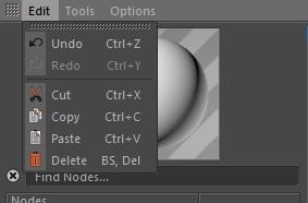
Edit Menu
Th Edit Menu includes some basic workflow options, along with their shortcuts.
Tools Menu
The Tools Menu includes a number of options to help you inside of the Shader Graph, described below:
Create Texture Node
Opens up your File Explorer and after selecting a texture, Redshift will automatically create a texture node inside our Shader Graph.

Create Texture Node
Connect Node to Output
This command will connect the output of the currently selected node to the Surface output. This is useful in conjuction with the IPR, for quickly previewing the output of any shader in the graph

Connect Node to Output
Tip: Binding this tool to a custom key can help speed up workflow.
Connect Node to Viewport
This command will connect the output of the currently selected node to the Viewport output. This is useful when editing the UVs for a specific texture in the graph.
Connect Node to Viewport
To adjust the texture resolution in the viewport, go to the editor tab in the materials attribute manager, demonstrated here.
Optimize All Nodes
Resizes nodes and deletes any inputs that don't have any connections.
Optimize All Nodes
Colorize Graph
Changes node's Title Color based on its category.
Colorize Graph
Options Menu
The Options Menu contains Auto settings that can be turned toggled on/off to help with workflow.
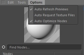
Auto Refresh Preview
Redshift will attempt to refresh all materials in your scene whenever you make changes to them.
Auto Request Texture Files
Whenever a texture node is dragged into the Shader Graph, Redshift will open the File Explorer by default.
Auto Optimize Nodes
Redshift will automatically optimize nodes inside your shader Graph while you work.
Editing the Shader Graph
Creating Nodes
Basic Node Creation
To create nodes we can go through the different categories or search for a specific node and drag it into a section of the Shader Graph.
Creating Nodes
Shortcuts
In the Shader Graph we can CTRL + Click and drag to copy a node(s). You can also resize nodes by CTRL double clicking them.
Edit Nodes
Drag and drop texture(s) from the File Explorer and Redshift will automatically create a texture node. Alternatively we can bring up our File Explorer and search for the file.
Creating Textures
Image Previews
To preview the image loaded into the texture node, click on the texture node and view the Attribute Editor. When using the C4D Shader node we can also preview our texture in the Attribute Editor. The Redshift Asset Manager can be used to preview all the textures used in our scene, as well as also drag-and-drop image previews to create a texture in our graph.

Image Previews
Substance Asset manager
Substances from the Substance Asset manager can be dragged & dropped and will connect to any available Redshift Material in the Shader Graph.

Substance Asset manager
Connecting Nodes
To connect nodes, drag from the source node Output port to a target node's Input port, or the top-left corner of the node and choose an available Input port. To easily expose an Input port for a specific parameter, drag it from the Attribute Manager into the node.
Connecting Nodes
XGroups
Redshift supports the use of XGroups, which are containers for nodes, in the Shader Graph. XGroups are not only containers, but can be connected to other nodes and XGroups demonstrated down below.
XGroups
Editing parameters without the Graph Editor
To make changes to a material without using the Graph Editor, we can select the material and view/adjust its parameters in the Cinema 4D Attributes Manager. There wont be as much control as using the Graph Editor, but can be useful for changing basic parameters on the fly.
Attributes Manager
Elements of the Shader Graph
Shader Nodes
Redshift Shader Nodes are very simliar to an XPresso Node's functionality, they have Input paramerters and Output parameters.
Input parameters
Input parameters, which can be viewed by clicking the top left (blue box) of our node, can sometimes be controlled by other shader nodes. Such as the input of a RS Ramp node can be driven by a RS Texture node.

Input parameters
Output parameters
Output parameters, which can be viewed by clicking the top right (red box) of our node, have different types. To view the type of Output port we can hover over the port or we can right click and view the Port information. Only ports that are compatible can be connected together, but our graph will do automatic conversions when possible. Example: Connecting a RS Color User Data Output (Color Type) to a Reflection Roughness Input (Real Type), Redshift wil convert our Color to a Real value to be used for the roughness.

Output Parameters
The Output Node
The Output Node represents the output of the entire material, every redshift graph has one. The Output node also holds the Material ID, that can be used for AOVs. The different Inputs are described down below:
Surface
Material surface output. Normally the output, from nodes, from the Materials category, are connected here. Although simple Utility or Texture nodes are also supported, can be useful to quickly preview a Fresnel curve or textures in the scene.
Surface Output
Displacement
Material Displacement output. Used with nodes from the Displacement category. Requires geometry to have displacement enabled through an Redshift Object tag.

Displacement Output
Environment
Material environment output. Used with nodes from the Environment category.

Environment Output
Volume
Material Volume output. Used with nodes from the volume category. Such materials are applicable only to Volume objects such as a Redshift Volume, or TFD Volume container. Volume materials should not have any other outputs connected.

Volume Output
Light
Light material output. Used with nodes from the light category. These materials are applicable only to Redshift Lights. Light materials should not have any other outputs connected.

Light Output
Viewport
Viewport output. Allows overriding the viewport preview with an alternative shader. This can also be useful to preview a certain texture in the viewport when editing UVs.
Viewport Output
Viewport preview resolution
Adjust the resolution of a texture in the viewport by going to the editor tab and picking a resolution, similar to built in C4D materials.
Viewport
Special parameters
UV Channel / Texture Space / Tangent Channel
The UV Channel, available in various nodes, is used to determine the source of UV's needed by the node, by default this channel will be left empty, so Redshift will use the UV's from the texture tag that holds the material. Alternatively you can set the name of (or drag and drop) a UVW tag. The node will use the raw UVs from a tag that matches the name, in any object that holds this material.

UV Channel
Vertex Attribute Name
The Vertex Attribute Name, for example in the Vertex Attribute Node, is used to determine the source of per-vertex Color data needed by the node. Weight-maps or Vertex Color tags can be used by entering the name of the corresponding Vertex attribute or by dragging and dropping the tag.
Vertex Attribute Name
Object Attribute Name
The Object Attribute Name, for example in the Scalar User Data node, is used to determine the source of per-object data needed by the node. This can be a Cinema 4D Object User Data Value (like in our example below) or a special value depending on the object such as Mograph Index Ratio, Particle Life, ect. In the example below a User Data named "Example" has been added to our cube, with a value of one. We will use the Scalar User Data to drive our RS Shader Switch and set the Shader one to red.

Object Attribute Name
Volume Channels
The Volume Channels in the RS Volume Node is used to select a specific channel provided by a volume object (VDB or TurbulenceFD). There is a preset button that offers options typically found in Volumes, but will be dependent on what is provided in the scene.
Volume Channels
AOV Names
The AOV Names, for example in the RS Store Color to AOV, are used to select or create an AOV for the custom AOV workflows.

AOV Names
Camera Picker
The Camera Picker,found in the Camera Map node is used to select a camera in the scene.

Camera Picker
Color Parameters
In Cinema 4D, the values of color-fields and other color-based parameters such as Ramps, are not fixed, but are interpreted differently based on the Linear Workflow and Input Color Profile options found in the Project Settings. While Redshift emulates the gamma correction behaviour of the built-in renderers with respect to these settings, we recommend keeping the Linear Workflow option checked, and selecting Linear as the input color profile setting particularly when working in conjuction with other DCCs. These two settings ensure that no color-correction applied, and color values are processed as is.
Special Nodes
C4D Shader
The C4D Shader node allows the use of Cinema 4D shaders in conjunction with RS Shaders. The built in Cinema 4D Shaders will be converted (Baked) into texture files, and then used typically with a RSTexture node for sampling the texture file. The C4D Shader is limited shaders that can be encoded into a 2D Texture, so other types of shaders (for example 3D shaders) are not supported.

C4D Shader
Using XPresso Nodes in the Shader Graph
XPresso can perform calculations based on the scene and can be used to drive shader parameters. XPresso nodes can connect to RS Shader Nodes, but RS Shader Nodes cannot connect to XPresso nodes. XPresso is evaluated once per-frame and will apply to all the objects that use the material.
Example: Distance Based Roughness
So lets take a look at how we can use Xpresso, to change the Roughness based of the distance of objects inside of the Shader Graph.
To start off we have a simple Redshift Sky setup, with an animated sphere moving towards a stationary sphere.

Animated Sphere
Now let's create a new RS Material and adjust some of the parameters. We will disable the diffuse and set the IOR to 0 to simulate a chrome material. Also let's go into the Advanced Tab, and check "Convert From Glossiness to Roughness". Then we will apply the new material to our Ball object.
Material Setup
Now let's open up our Shader Graph and start setting up our XPresso. First we want to drag and drop our two objects into our Shader Graph, this will automatically setup our object XPresso nodes. Next we want to expose our Global Positions for both objects as well.

Shader Graph
Next lets bring in a Distance XPresso node and plug our objects into the inputs. This will calculate the distance between the two objects. Also let's bring in a Result node to actually see the distance value.

XPresso - Basic setup
Now we need to remap this value to work with our Roughness Value. So let's bring in a Range Mapper node and we want to set the input Upper value to our result number, 2027.208. We can now plug our output into the roughness input.

XPresso - Remapping values
We can now hide our Origin Sphere, and scrub through our timeline. As you can see the closer we get to our Origin sphere, the rougher our material will get.

Distance Based Roughness