Table Of Contents
Introduction
Displacement mapping is a texture-based technique used to physically displace tessellated geometry. It can be controlled by either a vector texture or height map texture, which is used to perturb the surface geometry. Unlike its cheaper 'sister' shader (Bump Map), displacement mapping affects shadows, since the geometry is actually perturbed.
To chain displacement-maps together we supply a Displacement Blender shader node which has been optimized to efficiently blend resultant displacement vectors together.
The output of this shader is a displacement vector, which when attached to the material displacement input will result in a perturbed surface position and normal.
Prerequisites
To make displacement mapping work, you'll need to enable tessellation and displacement on your object.
Please see the Tessellation and Displacement page for instructions and information on how to do that.
Displacement Parameters
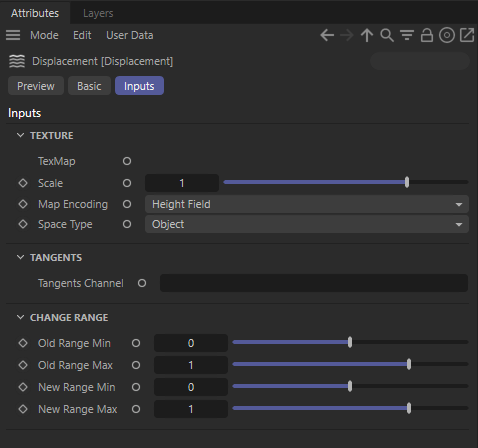
TexMap
Connect a texture sampling shader node here to set the displacement map input.
Scale
This scales the displacement value that is read from the texture. A value of 0.0 effectively disables the technique, yielding the original surface. Greater values increase the displacement effect. Negative values invert the direction of the displacement. The default is 1.0.
Map Encoding
This determines the type of displacement to do, given the texture input type:
- Vector – a floating point displacement vector
- Height Field – a height-field/bump-map scale along the surface normal
Space Type
When computing vector displacement, it can be done in the following geometry space:
- Object – the displacement map is expected to fit onto the object geometry
- Tangent – the displacement map can be applied to any geometry, providing it has a known uv tangent space
Only applicable to Vector type Map Encoding.
UV Set
Specify a UV Set other than the default here.
Change Range
Old Range Min / Max
The range of values that are read from the displacement/bump texture.
New Range Min / Max
The new range the values will be mapped to.
Displacement Example
Here is an example of how displacement mapping can enhance the detail of simple geometry.
The scene shows a plane that has been tessellated with the default mesh tessellation/displacement parameters. A displacement shader has been connected to the material displacement input and the displacement image is a vector map.

Notice how the 'Scale' parameter of the displacement shader is very small - this is because displacement is applied in world units and in this particular example, the mesh is very small, so we only need a small amount of displacement to yield a dramatic change in the geometry shape.
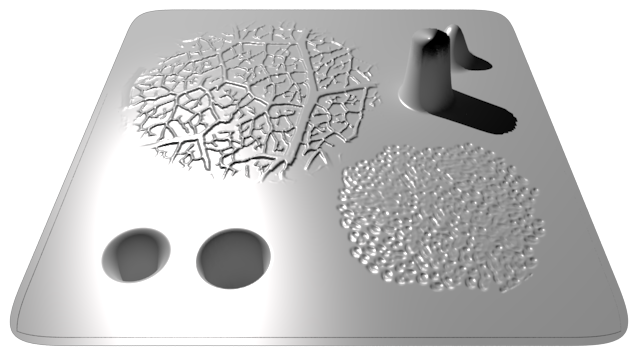
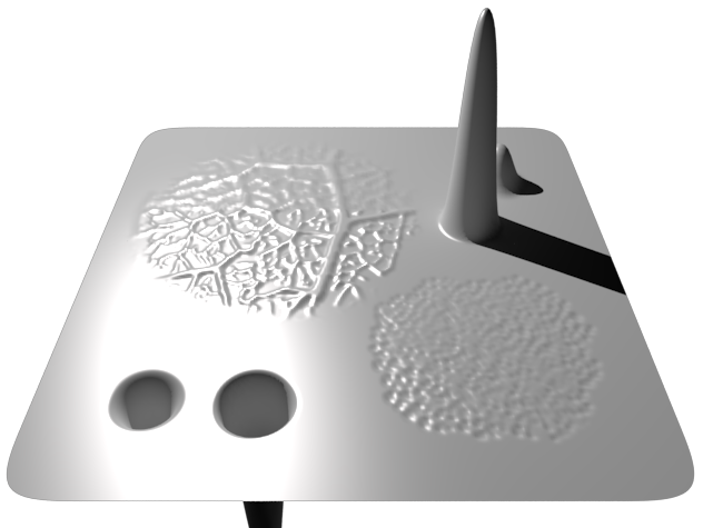
Here is the resultant render. See how the otherwise flat surface has geometric detail? The displacement vector map contains a different test in each quadrant. Top-left demonstrates fine perturbation high frequency detail coming out of the plane. Top-right demonstrates large perturbation low frequency detail coming out of the plane. Bottom-left demonstrates large detail, but as an indentation, going into the plane and bottom-right demonstrates fine detail going into the plane. More importantly, note how the top-right tower appears distorted and the lighting looks wrong - this is because the 'Max Displacement' of the mesh is default to 1.0 and so the displacement is being capped to that.
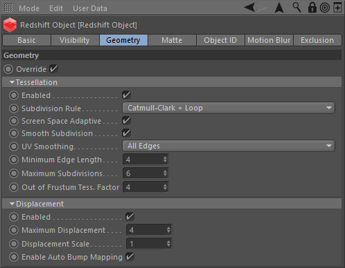
You can see here that to compensate for the stumpy tower, we increase the 'Max Displacement' setting in the mesh properties to 4.
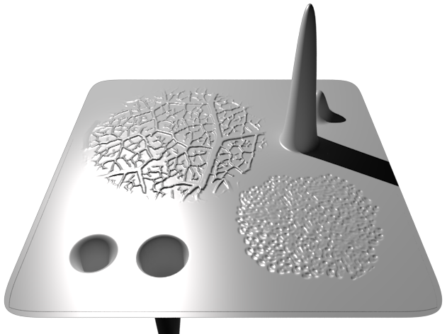
Here is the resultant render. See how the tower now stands in all its glory. At the bottom of the render you can also now see the indented tower.
This last image shows what the render would look like without 'Bump Mapping' enabled.
The low frequency detail towers don't look any different, but the finer, high frequency detail parts now look blurry. Without 'Bump Mapping', you would have to tessellate the mesh to a ridiculous level to get the same quality of detail, which of course, is not recommended.