Table Of Contents
- Introduction
- Object tab
- Details tab
- Project tab
Introduction
The Redshift Light is an all-purpose light which can be used to model point, spot, IES and directional lights as well as area lights of various shapes.
Object
Type
Specifies the light type.
- Point: A point light. Simulates a 'bare bulb' light which emits light in all directions from an infinitesimally small point in space.
- Spot: A spot light. Emits light in a cone-shape.
- Infinite: Simulates a light source which is infinitely far away from the scene. An infinite light has no position, only a direction. Therefore all light rays emitted are parallel and have no decay.
- Area: A light which has a real physical size and shape.
- Dome: Simulates light emitting from a large sphere that always surrounds the entire scene. You can think of this as a sky that illuminates your objects and that can also be mapped with an image, for example. The dome light can thus also be used like a Cinema 4D Sky object.
- Photometric IES: Allows to load an IES Profile files to control the amount and direction of emitted light.
- Portal: A special type of light source that can optimize the calculation of global illumination. Often used in window frames for interior renderings to optimize the rendering of indirect light coming through the windows.
- Physical Sun: Similar to the Infinite light, but specially designed to mimic sunlight, including a color change depending on the angle of incidence of this light source.
|
|
|
|
|
| Light Type: Area | Point | Spot | Infinite |

Add Graph
Many settings of the Redshift light object can also be set through the material node system. Using this button will create a new Redshift Shader Graph material and connect it to this light.
Light parameters controllable by a light shader include the lights Color settings, Decay, Shadow options and Attenuation.
Edit Graph
If a Shader Graph material has been asigned to the light, you can open the Redshift Shader Graph by using this button and edit the shader directly there.
Add Target Tag
Add Target Tag and Null
You can find these commands in a menu to the right of the Type menu. You can use them to add a Target expression tag to the light. By linking an object to that tag you can aim the z axis of the light to that object. Using the Add Target Tag and Null command creates an additional Null object and uses that as the Target Object with the Target expression tag.
Preview
Certain light types can be previewed in the Cinema 4D editor viewport. For these lights the following options will become available in the Object tab.

Blend Object Color
In the Basic tab of the Redshift light object you can find an option to choose an individual Display Color. Activate this option to use that color also for the Wireframe preview of the light.

On the left side you can see how the light object has been assigned a red color. Without the "Blend Object Color" option enabled, only the spot's star icon in the viewport will be colored. If the option is enabled, the wireframe cone of the spot will also be colored, as you can see on the right side of the image above. However, this option does not change the color of the light for rendering.
Wireframe
Displays a wireframe representation of the light decay or light direction in the viewport. When this option is checked, some light types allow manipulation of certain parameters directly in the viewport.
Illumination
Provides an approximation of the illumination of the light in the viewport.
Illumination Adjustment
Adjusts the viewport illumination scale.
These options only affect the Cinema 4D viewport and have no effect in the IPR or when rendering.
Intensity
Intensity
Specifies the intensity of the light or the number of physical units (see below).
Exposure (EV)
Specifies an f-stop value that allows you to intuitively increase/decrease the light's intensity when matching to a plate, or rendering large/tiny scenes without using hugh/miniscule Intensity Multiplier numbers. A value of 0.0 means the intensity does not change.
For example, an Exposure value of 1.0 means the light doubles in intensity and a value by 2.0 means the light quadruples in intensity, etc.
Units
Specifies the physical units to use for the light intensity.
- Image: use non-physical units.
- Luminous Power (lm): use lumens. The light intensity will not be affected by the area of the light.
- Luminance (cd/m^2): use candela/m^2.
- Radiant Power (W): use Watts. The light intensity will not be affected by the area of the light.
- Radiance (W/sr/m^2): use Watts/steradian/m^2.
Luminous Efficacy (lm/w)
Specifies how many lumens are emitted per Watt. Only relevant when using Radiant Power or Radiance unit types.
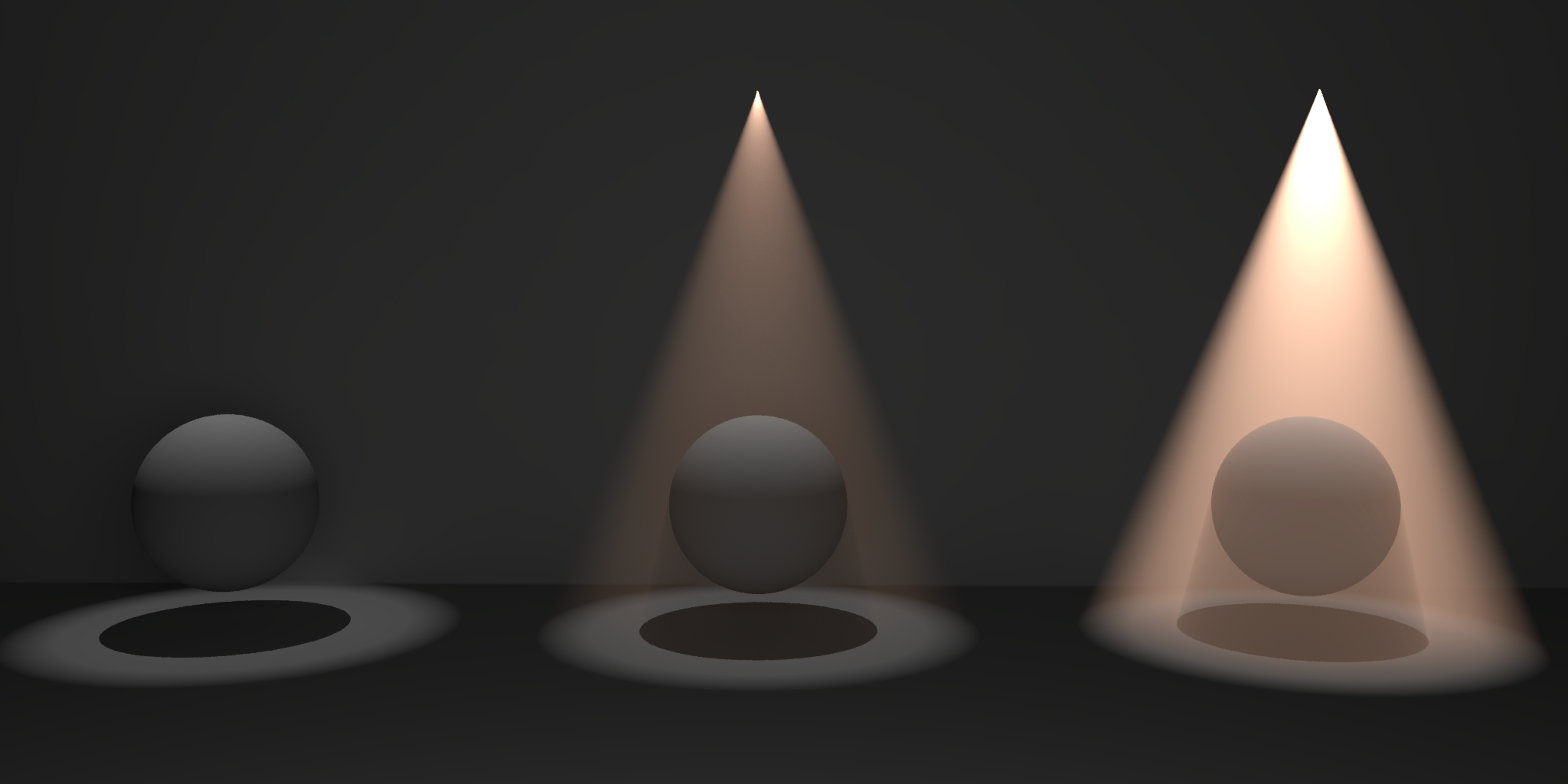
Decay
Specifies the decay of the light;
- None
- Linear
- Quadratic
For physical correctness you must use the 'Quadratic' decay option.
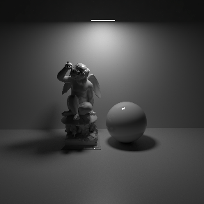
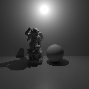
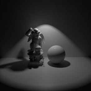
Decay Types in Detail
In the example below the light source in the bottom right has its decay type switched between the 3 different types. Quadratic is physically accurate based on the light's size and intensity. Linear demonstrates how you can specify the start and stop falloff to control exactly where the light starts to be visible and then decays to nothing. None turns off decay entirely.
|
|
|
|
| Decay Type: Quadratic | Linear | None |

Start
Specifies the distance from the light at which Linear fall-off occurs.
Stop
Specifies the distance from the light at which Linear fall-off ends.
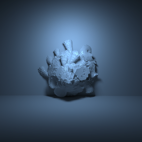
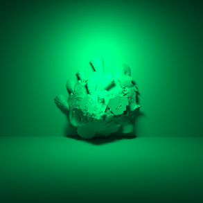
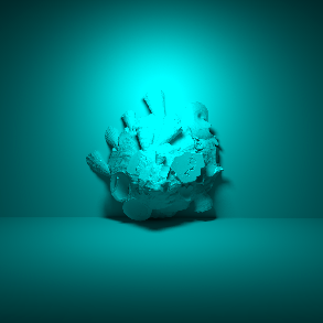
Color
Mode
Specifies the color mode.
- Color: Light color is specified by the Color parameter below.
- Temperature: Light color is specified by the Temperature parameter below.
- Color and Temperature: Light color is specified by both the Color and the Temperature parameters below.
Color
Specifies the color of the light by using the standard color chooser options.
Temperature (K)
Specifies the color of the light using a color temperature value (in Kelvin). Redshift supports color temperatures between 1667K and 25000K. Lower values are 'warmer' or more red, while higher values are 'cooler' or more blue.
|
|
|
|
|
|


Temperature
Temperature mode demonstration ranging from low values resulting in warm tones on the left to high values resulting in cool tones on the right.
|
|
|
|
|
|


Color
Color mode demonstration ranging from reddish tones on the left to bluish tones on the right.
Texture
You can load a bitmap image here to color the light and to use it like a projector.
Shape
Area Shape
Specifies the physical shape of the area light;
- Rectangle
- Disc
- Sphere
- Cylinder
- Mesh
|
|
|
|
|
|
| Area Shape: Rectangle | Disc | Sphere | Cylinder | Mesh |


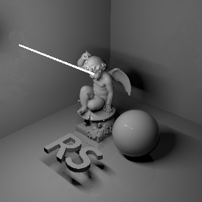
Mesh
Here you can link to your geometry, that is then used to emit light. See Mesh Lights for info on how to use them.
Size X
Size Y
Size Z
It depends on you Area Shape choice if and how many of these settings you can access. Use them to scale the chosen shape.
Spread
Enables directionality control for Rectangle and Disc Area lights, similar to a barn door effect or spot light. The lower the Spread, the more the light is concentrated in the direction of the light normal. A Spread value of 1.0 is the default, physically correct lighting behavior, while a value of 0.0 makes the light a parallel light.
Note that a Spread of 0.0 is close to a fully directional light, but the light rays will not be perfectly parallel. This is due to a mathematical sampling limitation.
|
|
|
| Spread: 1.0 | 0.3 |
Cone Angle
This is only accessable for a Spot light and specifies the angle of the spot light cone.
Below shows three physical lights set to 'spot' with cone angle values smallest on the left to largest on the right:

Falloff Angle
This is only available for a Spot and specifies the angle over which light falls off at the edge of the spot light cone. Smaller values will produce a sharper edge.
Below shows three Spot lights with Falloff Angle values smallest on the left to largest on the right:

Falloff Curve
This is only available for a Spot and changes the light intensity distribution within the light cone. With increasing values the light intensity will decrease faster between the center and the outer border of the spot cone. The images below show a spot aiming straight at a wall. The only difference between the images is the value for the Falloff Curve.
|
|
|
| Falloff Curve: 0.0 | 50.0 |

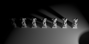
Visible
Controls the primary visibility of the light.
A visible light will block you from seeing through them both from the front and back. If a light is visible, it will cast shadows from other lights.
The image shows a rectangular light with visibility enabled on the left and disabled on the right. Note that there is no difference in the light distribution here. However lights with visibility enabled will cast shadows from other lights in the scene.
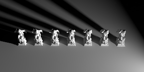
Bi-directional
Enables bi-directional lighting such that light is emitted on both sides of the shape. Only valid for Rectangle and Disc area shapes.
The image shows a rectangular light with Bi-directional disabled on the left and enabled on the right.Note how the light comes out of both sides with bi-directional enabled.
Normalize Intensity
Removes the area of the light from the lighting calculation. Enabling this option prevents the light intensity from changing when the size of the light changes.

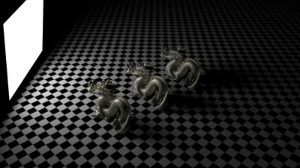
Shadow
Cast Shadow
Enable or disable shadow casting.
Transparency
Specifies the transparency of the shadows cast by the light. Smaller values yield darker shadows. The default value of 0 will produce a completely black shadow. A value of 1 will produce no shadow at all.
The example below shows how a completely opaque sphere's shadow transparency can be controlled by this light setting.
|
|
| Transparency 0 to 1 |

Softness
Specifies edge softness for non-area light shadows. A value of 0 means no softness and will yield sharp shadows. Values above 0 will produce softer shadow edges.
Softness is only available for Redshift Physical and Redshift IES lights.
|
|
| Softness 0 to higher values |

Softness Affects Gobo
Enables soft gobo texture projection, to match the softness of the shadows, giving the same appearance as if the light was an area light.
Softness Affects Gobo is only available for Point, Spot, Infinite and Photometric IES lights.
Light Group
AOV Light Group
This is the name of the AOV light group this light is associated with.
For more information on Light Groups and how to set them up and use them please see here.
Contribution
Matte Shadow Illuminator
Specifies whether the light can illuminate 'Matte Shadow' surfaces (see Matte Shadow Catcher shader).
Matte Shadow Illuminator is not available for Dome, Portal and Physical Sun lights.
Affected by Refraction
This option allows you to control how specular reflections are affected by rough/refractive objects that block the light and whether or not the light rays bend as they pass through. Prior to 2.6.10 this option was not available and the light rays would never bend. Specular ray bending is an important effect for rendering realistic-looking glass and lenses.
- Never - Specular rays do not bend. This is the legacy lighting behavior.
- Auto - Specular rays bend through refractions if they are not too rough and bias towards not bending if they are rough.
- Always - Specular rays bend through refractions regardless of ray roughness.
This effect is available only for area lights and dome lights. Spot and IES lights can not be seen through bent rays because their source is infinitesimally small.
Care must be taken when using 'Always', as this can disable Multiple Importance Sampling, which is a crucial technique for getting clean renders for rough surfaces.
Light/Shadow linking is not available for specular rays that have been bent.
GI Max Trace Depth
This option lets you override the maximum trace depth for GI rays on a per-light basis.
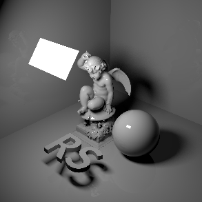
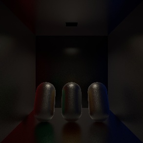
The following Contribution parameters allow you to tweak a lights contribution to different shading elements individually. These parameters give you full creative control to adjust exactly how much a light impacts a shaders various elements, they can even bet set above 1.
The example scene used below contains 3 capsules with different shaders that collectively showcase 'Diffuse', 'Reflection' (specularity), 'Single Scattering' (refraction), and 'Multiple Scattering' (sub-surface scattering) shading elements. At the top of the room is a Redshift Area light with Contribution values of 1 for all parameters unless otherwise specified and a small amount of volume scattering. For reference, here is an example of what those elements look like on their own so you can better understand what the Contribution example images are affecting.
|
|
|
|
|
|
| Diffuse | Reflection / Specularity | Refraction / Single-Scattering | Multiple Scattering | Beauty |


Diffuse
Scales the intensity of the light's diffuse contribution.
|
|
|
|
| Diffuse: 0 | 1.0 | 2.0 |


In the first image since diffuse scale is set to 0 there is also no global illumination contribution.
Reflection
Scales the intensity of the light when seen through reflections/specular or refractions.
Sometimes very bright lights can appear noisy when seen through 'rough' reflections/refractions, even with hundreds of samples. Bringing down the intensity can help reduce noise.
|
|
|
|
| Reflection (Glossy): 0 | 1.0 | 10.0 |
Transmission
The intensity of the specular component or the reflection when seen from behind a refractive object. You can see the effect in the images below. Reducing the Transmission results in a missing reflection of the area light on the sphere behind the glas object..
|
|
|
| Transmission: 1.0 | 0.0 |
Single Scattering
Scales the intensity of the light when seen through single scattered materials and refractions. A value of 0.0 disables single scattered lighting.
|
|
|
|
| Single Scattering: 0 | 1.0 | 4.0 |

Multiple Scattering
Scales the intensity of the light when seen through sub-surface multiple scattered materials. A value of 0.0 disables multiple scattered lighting.
|
|
|
|
| Multiple Scattering: 0 | 1.0 | 4.0 |

Global Illumination
Scales the intensity of the light's global illumination contribution. A value of 0.0 disables global illumination lighting.
|
|
|
|
| Global Illumination (GI): 0 | 1.0 | 4.0 |


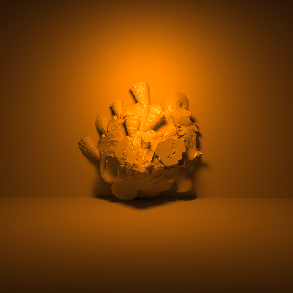
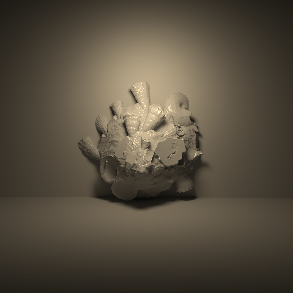
Volume
Sets the amount of light that is scattered in rendered volumes
|
|
| Increasing the 'Volume' contribution scale value from left to right. |
Caustics
Caustic Photons
Enables caustic photon casting for the light.
Has no effect if Enabled is not activated for Caustics in the Redshift Render Options under the Caustics tab.
Intensity
Specifies a multiplier for the caustic photon intensity, relative to the intensity of the light. A value of 1 will cause the emitted photons have the same intensity as the light. Smaller values will yield photons with relatively less intensity than the light, while larger values will yield photons with relatively more intensity.
Photons
Specifies the number of caustic photons to shoot for the light.
Project
In this tab, objects-specific lighting behavior can be specified.
You can find more specific examples about using these settings for Light Linking and Shadow Linking on this page.
Mode
Specifies whether the objects in the list should be excluding or included with respect to the light settings.
Objects
The list of objects that should be affected (in Include Mode) or not affected (in Exclude mode). For each object in the list the light behavior can modified to receive light, receive shadows, and to affect the object's children.