Table Of Contents
Introduction
A common issue when rendering thin hair geometry is aliasing, which can come in the form of moire or noise-like visual artifacts. The problem exists because thin hair can easily get 'missed' by camera rays.
"Min pixel width" is a technique that alleviates such aliasing issues by automatically thickening hair strands and making them appropriately semi-transparent to compensate for the thickening.
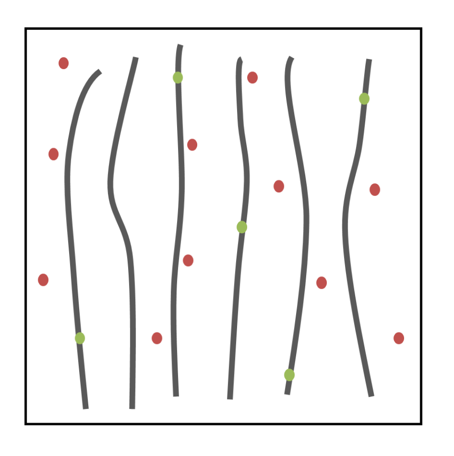
The figures below demonstrate how this works. The enclosing square represents a single pixel's footprint. The dots represent unified samples and, as it can be seen, there are 16 of them. Green dots are unified samples that managed to intersect hair while red dots represent ones that missed it. On the left image, the hair is thin enough where most unified samples miss it. This means the pixel doesn't show an accurate representation of the hairs it contains, which comes in the form of aliasing and noise. Clearly, if there were more unified samples, there would be more chances of hitting the hair and the pixel would be 'cleaner'.
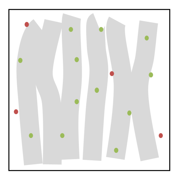
On the right image, the effect of min pixel width is shown. The hair is now thickened and made more transparent. As a result, most of the unified samples can intersect the hair geometry. The pixel, therefore, gets a much more accurate representation of the hairs it contains and will render cleaner.
|
|
|
|
Without Hair Min Pixel Width |
With Hair Min Pixel Width |
"Min Pixel Width" introduces semitransparency so it can impact render times! However, since it helps render smooth hair with fewer unified samples, its use can yield an overall gain in terms of render times. This is especially true when the rest of the frame renders fine with a reasonable number of unified samples.
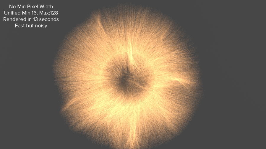
The following series of images show how the hair min pixel width technique works in practice. Even though our geometry is in no way representative of a real-life scene it, nevertheless, represents the pathological combination of thin hair with bright lighting. Such a combination significantly accentuates aliasing artifacts so it's ideal for our demonstration purposes.
Settings
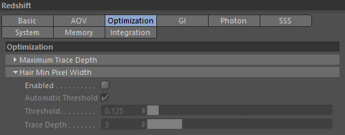
Enable
Enables/Disables the min pixel width technique
Automatic Threshold / Threshold
The 'threshold' parameter controls the amount of thickening that'll happen. The value represents the fraction of the pixel by which the hair will be thickened. Therefore, the larger the value, the more thickening will happen. A value of 1.0 means "as thick as the pixel" while a value of 0.125 means "an eighth of a pixel".
A higher level of thickening means more semi-transparency and, therefore, longer rendering times. It is, therefore, advised that users keep this parameter as low as possible. If the scene needs plenty of unified samples for other reasons (depth of field or motion blur), the min pixel technique will work fine with less thickening, i.e. smaller thresholds. Too low of a threshold, on the other hand, means hair will start getting missed again by unified samples which, in turn, means the min pixel width technique will be less effective and the rendered images will be noisier.
The "automatic" option will compute a threshold based on the number of unified samples.
We recommend that most users use the automatic setting.
Trace Depth
As mentioned previous, the min pixel width technique thickens hair and makes it semi-transparent. The trace depth setting controls the number of transparency levels. When the trace depth is exhausted, the min pixel technique will be automatically disabled, so the hair will no longer get thickened and semi-transparent. Practically speaking, this means that hair behind several layers of other hair will start rendering noisy again. However, because it'll be obstructed by these "in front" layers, the noise might no longer be visually important.
In other words: the larger the trace depth, the longer the min pixel width technique works and the higher the quality. The "how to use" guide below elaborates more on that point.
How To Use
After the hair min pixel width technique is enabled, we recommend using the automatic threshold setting enabled. From that point onwards, the only setting the user will care about is the trace depth setting as well as the global unified samples (in the Output tab). For thin hair rendering, we recommend using around 64-128 unified samples.
Please note that the min pixel width trace depth is related to the global trace depth limits. Therefore, if you intend on increasing the min pixel width trace depth, you'll need to ensure that the "combined" trace depth is sufficiently large. Redshift will issue a render-time warning if that's not the case.
As mentioned above, the trace depth control defines the "depth" (layers of hair) until which the min pixel width technique will be functional. A low trace depth setting means that the first few layers of hair will render clean and, whatever hair is behind them, will render noisy. On the other hand, a trace depth that is too large means that Redshift will have to compute a lot of semi-transparency which can increase the render times considerably!
A trace depth setting between 4 and 6 is usually sufficient. Having said that, we recommend users experiment with it in order to reach their desired "quality vs render time" target.
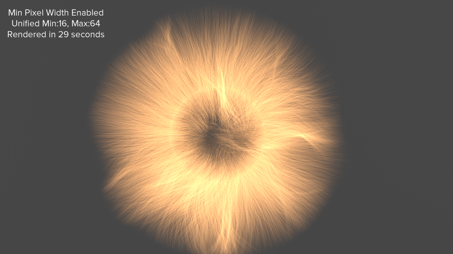
The pictures below show rendered examples of a few different trace depths. In all images, the hair min pixel width threshold was set to 0.25 and the unified sampling was set to min 16, max 64 and an error threshold of 0.003.
Please note that the min pixel width threshold was intentionally set 0.25 in order to make the effect of the trace depth parameter more visible. A smaller threshold would be more suitable for our 64 unified samples.
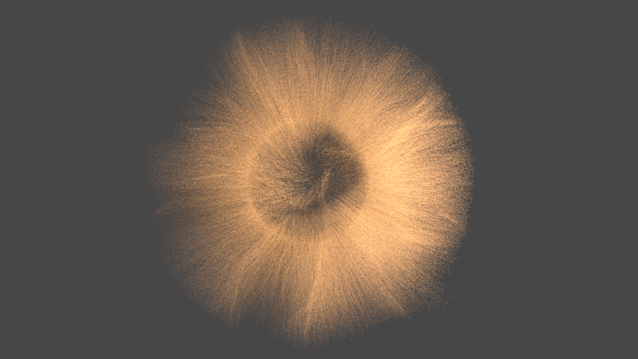
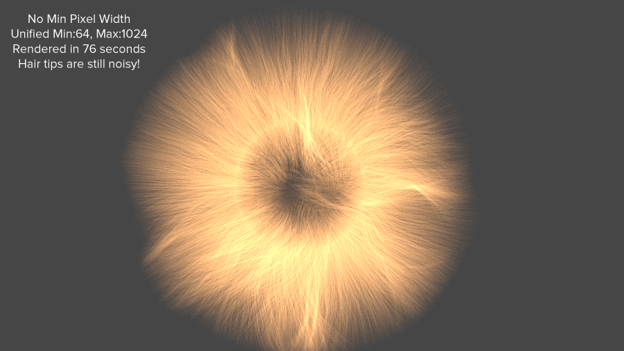
No Min Pixel Width

Trace depth set to 2. An improvement, but the results are still noisy. The noise is mostly where there are multiple layers of hairs.

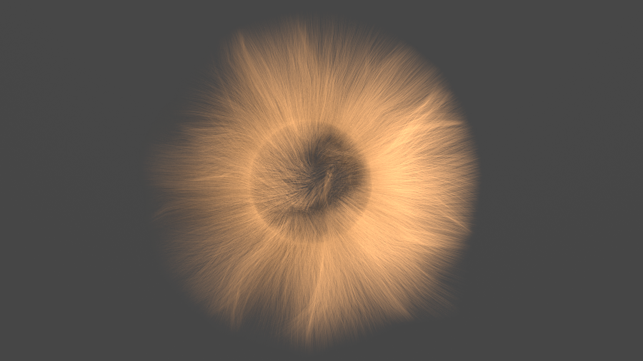
Trace depth set to 4. A significant improvement, but there are still a few noise artifacts around where there are multiple layers of hair.

Trace depth set to 6. Most of the artifacts are gone.

Trace depth set to 8. A minor improvement versus the trace depth 6 case.
Trace depth set to 16. A near-identical image to the trace depth 8 case.