Table Of Contents
Introduction
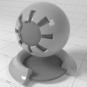
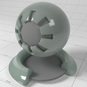
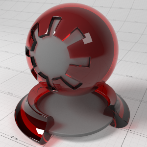
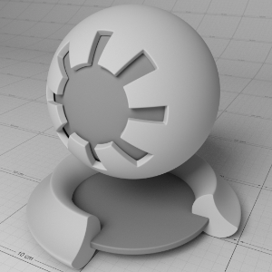
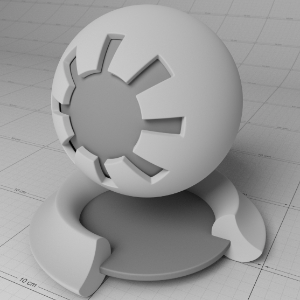
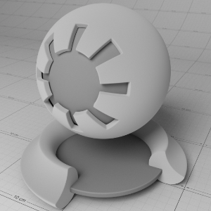
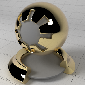
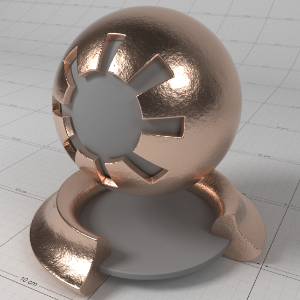
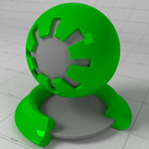
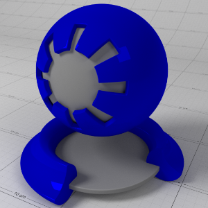
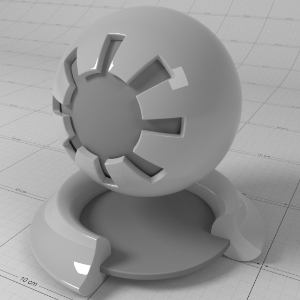
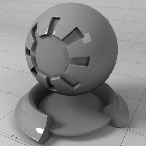
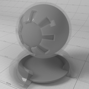
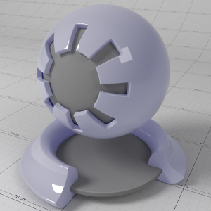
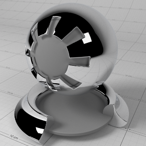
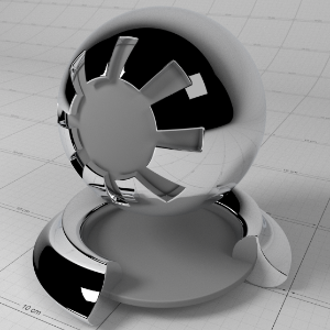
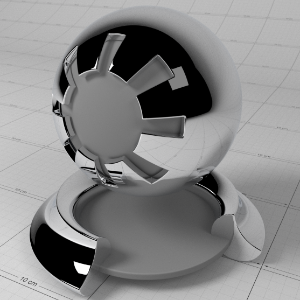
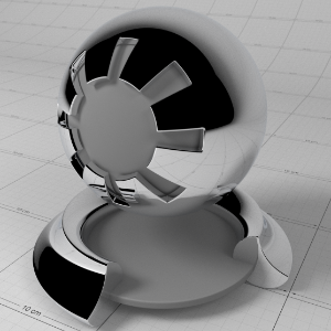
This is a general purpose material that is physically plausible, energy conserving and aligned with 'PBR' based principles. It offers two layers of reflection (a coating and base reflection), transmission/refraction, diffuse lighting and sub-surface scattering to accurately model a wide variety of materials ranging from glass, metals, plastic to skin.
The material is grouped into several sections:
- The 'Base Properties' section contains the most commonly used properties of a material, covering diffuse, reflections, sheen, refraction, sub-surface transmission and single scattering effects.
- The 'Sub-Surface Multiple Scattering' section contains properties for sub-surface multiple scattering for modeling complex materials such as wax and skin.
- The 'Coating' section contains properties commonly used for clear-coat reflections.
- The 'Overall' section contains properties applied to the material as a whole, such as opacity.
- The 'Optimizations' section contains properties that allow you to fine-tune the performance of the material.
- The 'Advanced' section contains properties not commonly used, but necessary for extra control.
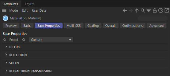
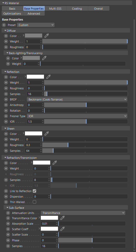
Base Properties
The 'Base Properties' section defines the most commonly used features of a material, such as diffuse, reflection and refraction/transmission.
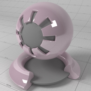
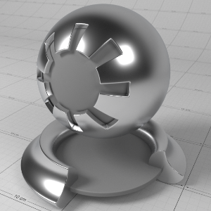
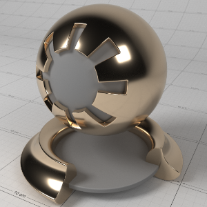
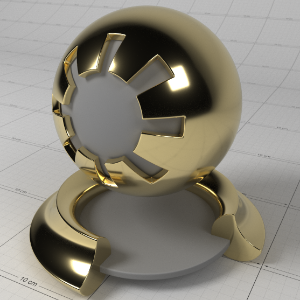
Preset
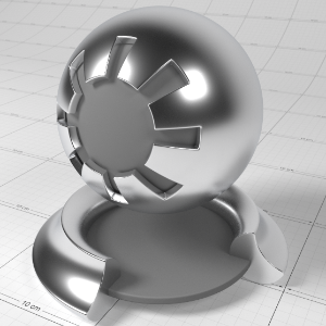
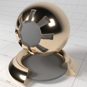
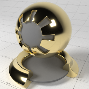
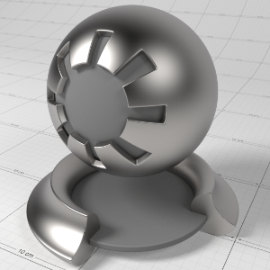
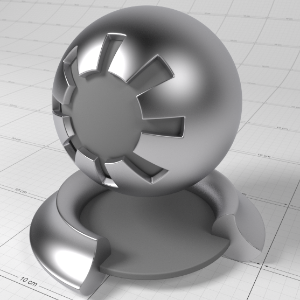
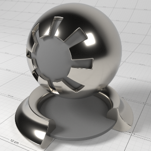
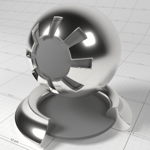
To help you get started, in the 'Base Properties' section of the material there is a 'Presets' drop-down that lists some pre-defined material settings. The presets show how to make metals using complex IOR, glass, single-scattered and multiple scattered materials.
|
|
|
|
|
|
| Glass | Water | Plastic | Aluminuim | Copper |
|
|
|
|
|
|
| Gold | Iron | Lead | Platinum | Silver |
|
|
|
|
|
|
| Milky Coffee | Jade | Paper | Tinted Glass |
|


Diffuse
Color
This defines the color of the surface when reflecting diffuse direct lighting or indirect global illumination. Setting this to black means no diffuse lighting.
When in PBR ' Metalness ' mode, this is also the color of the metal.
Weight
This scales the overall amount of diffuse lighting, with 0.0 meaning no diffuse and one meaning maximum diffuse.
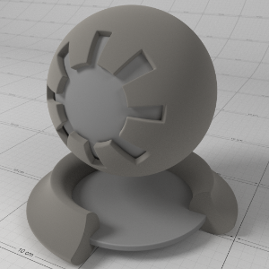
Roughness
This controls the 'roughness' of the diffuse lighting and is useful for simulating matte/dirty surfaces. This material implements the Oren-Nayar shading model to emulate rough surface micro-facets. A roughness of 0.0 is equivalent to a perfectly smooth surface, or traditional Lambert shading.
|
|
|
|
|
|
| Roughness 0.0 | 0.1 | 0.2 | 0.5 | 1.0 |
Back-lighting/Translucency
Very thin materials that have an amount of translucency from sub-surface scattering, such as paper or leaves, can use the 'Back-lighting/Translucency' options as a cheap solution to emulate the effect of sub-surface scattering. For thick translucent materials that have body, such as wax and liquids, you should use the sub-surface scattering features of this material (see single scattering and multiple scattering ).
Color
This is the back-face diffuse color of the surface. When non-black, light will be able to shine through to give a translucent effect. This is useful for lighting very thin materials, such as paper or leaves and is cheaper than sub-surface scattering.
Weight
This scales the overall amount of diffuse translucent lighting.
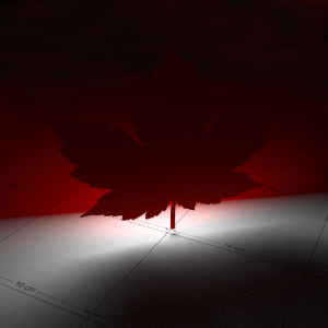
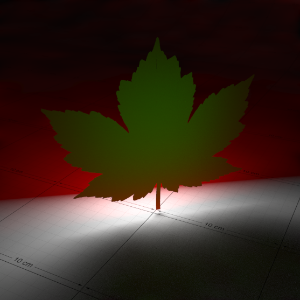
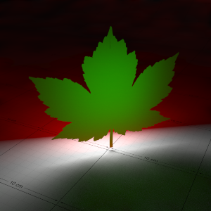
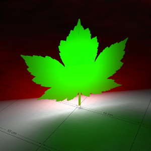
Translucency in Detail
Below is an example that shows the effect of a light shining through a thin translucent object, with various degrees of translucency. With one light in the scene, behind the object, this example also shows the effect of GI as the light passes through.
In this demonstration the front-facing diffuse color of the leaf is red, while the back-lighting color is green, to differentiate between front and back lighting.
|
|
|
|
|
|
|
Back-lighting Weight: 0.0 Diffuse Color: (1.0, 0.0, 0.0) Back-lighting Color: (0.0, 1.0, 0.0) |
0.01 |
0.05 |
0.1 |
0.25 |

Reflection
Most real-world materials exhibit an amount of reflection. The two most visible aspects of reflection are its blurriness (driven by material roughness) and its strength (driven by the Fresnel effect).
Color
This is the reflection tint.
To be physically correct, this should be white and the IOR/Reflectivity for each RGB channel should be used instead to add color.
Weight
This is a multiplier of the reflection tint. Reflections are disabled when this value is 0.0.
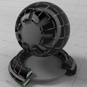
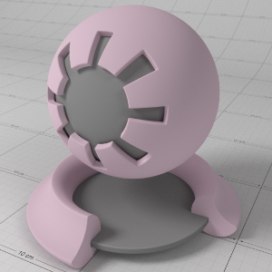
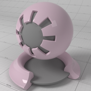
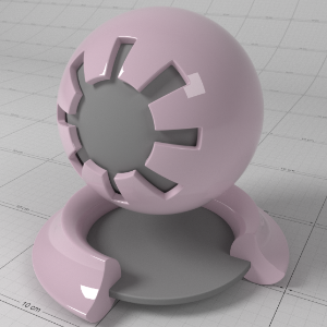
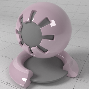
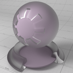
Roughness
This is the roughness of the surface reflection. A roughness value of 0.0 means perfectly 'polished', or full glossiness. A roughness value of 1.0 means almost diffuse appearance.
Samples
Blurry reflections (when "Roughness" is greater than 0.0) will need multiple samples to get a clean "grain-free" result. Higher numbers will reduce any potential grain issues but will take longer to render and vice-versa.
BRDF
This allows you to select which reflection model to use;
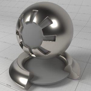
- "Beckmann (Cook-Torrance)" is a physically-based industry-standard reflection model that accurately represents a wide variety of materials.
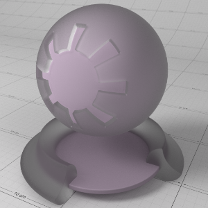
- "GGX" is a relatively new model that offers a wide specular tail, making it perfect for difficult to emulate metals such as chrome.
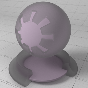
- "Ashikhmin-Shirley" is good for a wide variety of materials and samples efficiently for noise-free results.
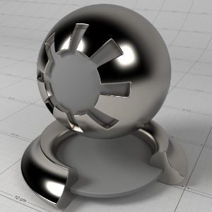
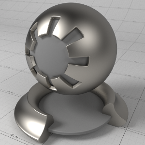
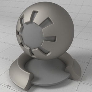
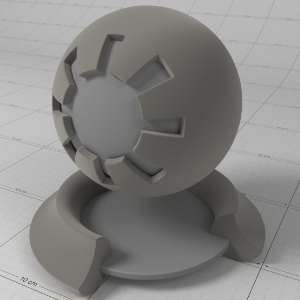
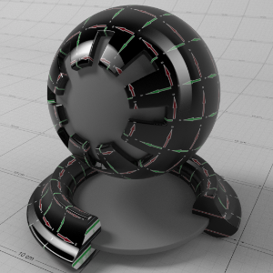
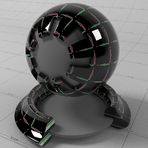
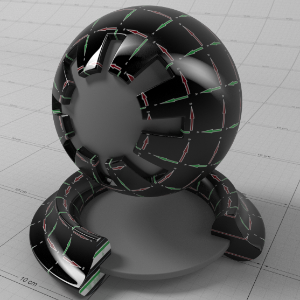
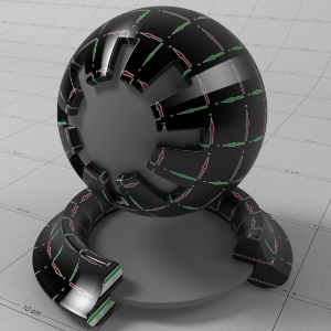
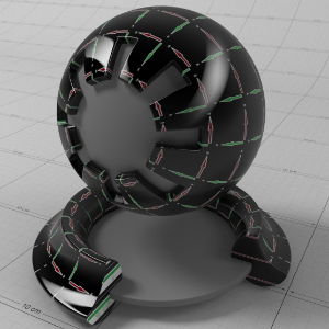
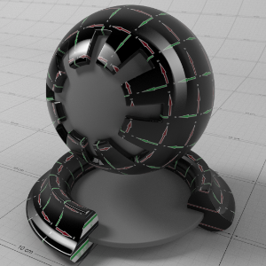
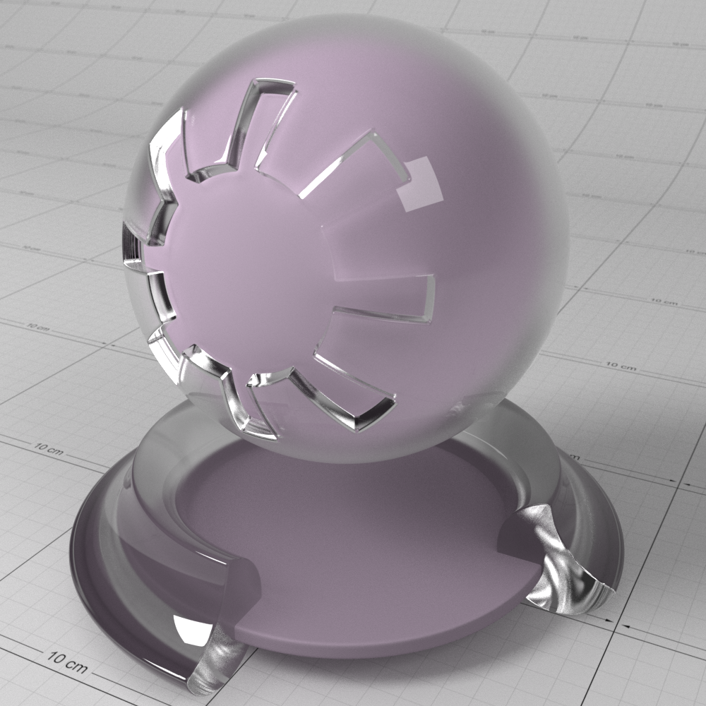
BRDF and Reflection Roughness in Detail
The roughness of a material describes how micro-facet surface perturbations affect light reflections. A perfectly smooth surface will reflect light like a polished mirror, while a rough surface will scatter the reflection in multiple directions.
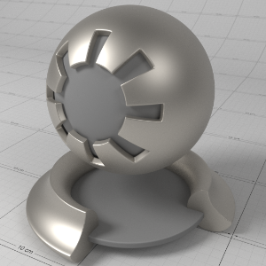
Redshift supports three different BRDF models to simulate micro-facet perturbations: Beckmann (Cook-Torrance), GGX and Ashikhmin-Shirley. Each BRDF is physically correct, efficient and energy conserving, and are proven for accurate general purpose reflections. The relatively new GGX BRDF has the added advantage of exhibiting a wide specular tail, which is a phenomenon seen on polished metals such as chrome.
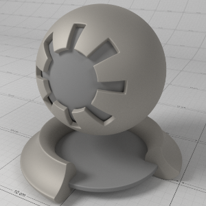
Below shows how reflection roughness affects the material for each BRDF type.
Note that the rougher the materials are, the noisier results. Rougher materials require more samples to clean up reflection noise, though at the expense of longer render times.
|
|
|
|
|
|
|
Beckmann BRDF
|
0.25 |
0.5 |
0.75 |
1.0 |
|
|
|
|
|
|
|
GGX BRDF
|
0.25 |
0.5 |
0.75 |
1.0 |
|
|
|
|
|
|
|
Ashikhmin-Shirley BRDF
|
0.25 |
0.5 |
0.75 |
1. |

Anisotropy
This allows to you stretch reflections in a particular axis; -1 to 0 for x/u axis and 0 to 1 for y/v axis, with 0.0 meaning isotropic. Anisotropy is used to emulate materials such as brushed metals where surface roughness is focused in a particular direction.
Rotation
This allows you to rotate the anisotropic effect, which can be used for emulating materials such beaten metals.
Anisotropy in Detail
'Anisotropy' is used to stretch roughness in a particular axis, which enables modelling of materials such as brushed metals. For the best results a consistent orientation axis for anisotropy should be defined (see ' Surface Orientation' in the ' Advanced' section).
Below shows an example of changes in 'Anisotropy'. The red arrows on the textured surface point in the U direction and the green arrows point in the V direction. See how the rectangular specular highlights stretch with changing anisotropy:
|
|
|
|
|
Ashikhmin-Shirley BRDF
|
0.5 |
0.0 |
In conjunction with 'Anisotropy', ' Rotation' is used to control the orientation of the surface roughness axis. Using a texture that describes rotation, you can define interesting looking materials such as pounded metals.
Below shows an example of changes in 'Rotation', with 0.25 representing a rotation of 90 degrees:
|
|
|
|
|
|
|
Rotation: 0.0
|
0.125 |
0.25 |
0.375 |
0.5 |
Fresnel Type
This allows you to select between different methods of controlling the reflection Fresnel effect;
- " IOR (Advanced)" lets you set the Index of Refraction for each red, green and blue channel. This allows you to control the reflectivity color for both dielectric materials (i.e. non-metals) and metals, while remaining physically correct. This mode also lets you set the 'Absorption/k' values required for metals. 'Absorption/k' should be 0,0,0 for non-metals.
- " Color+Edge Tint" is an artist friendly mode that allows you to control the facing reflectivity color and metal edge tint, without required complex IOR values. The 'Metal Edge Tint' should be black for non-metals.
- " Metalness" is a special mode designed for 'PBR' workflow compatibility with 'Substance' and 'Unreal' materials.
- " IOR" lets you set a single Index of Refraction value to control reflectivity and is ideal for simple dielectric materials. Dielectric materials typically have an Index of Refraction between 1.0 and 2.0, where 1.0 means no reflectivity and higher values mean stronger reflectivity.
Fresnel Reflectivity in Detail
Reflective materials can be generally split into two categories: dielectrics and conductors. Dielectric materials are things like water, glass, wood, plastic. Conductor materials are metals. Fresnel reflectivity realistically emulates reflection strength for these different kinds of materials, describing the facing reflectivity strength of the surface to the eye, with perpendicular reflectivity ;around the silhouette of an object falling off to white.
The 'Fresnel Type' option offers multiple modes to allow you to control the reflection strength and 'Fresnel effect' for different kinds of materials and they are covered below in their appropriate sections in detail.
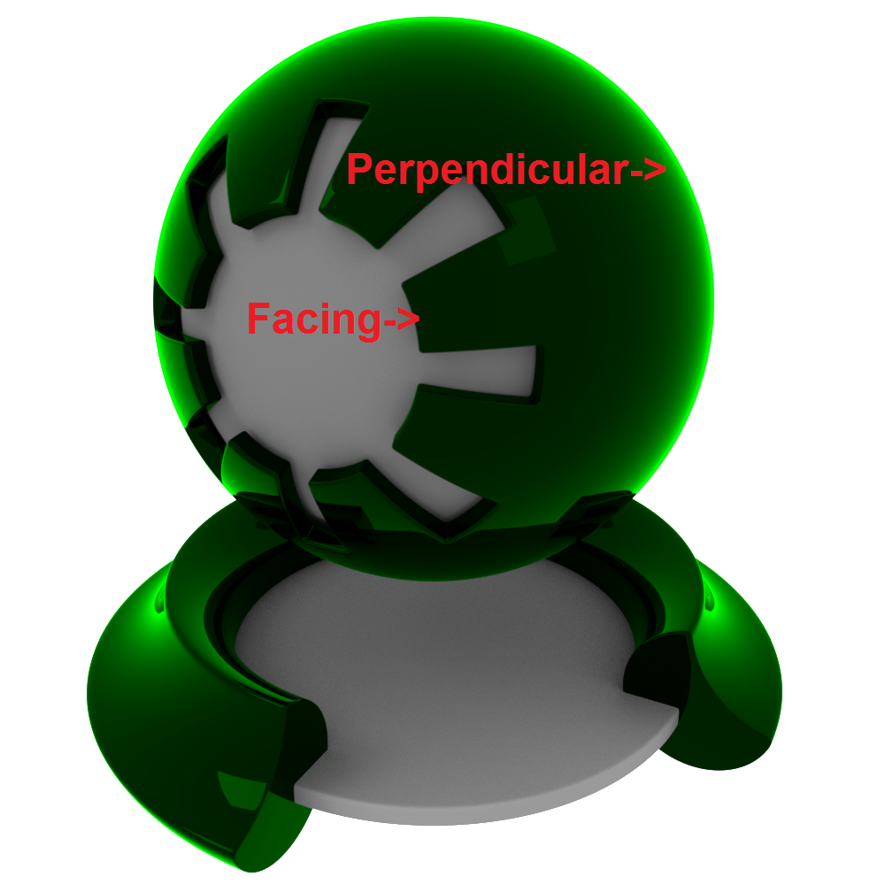
Above shows an example of the 'Fresnel effect' of facing reflectivity vs perpendicular reflectivity, tinted green to highlight the effect:
IOR
The index of refraction used to calculate the strength of the Fresnel effect.
Consists of three values (for red, green and blue) when using "IOR (Advanced)" Fresnel.
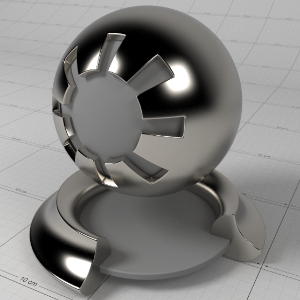
Fresnel Type mode "IOR" In Detail
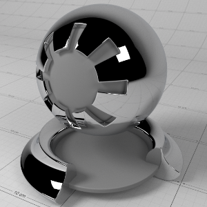
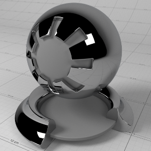
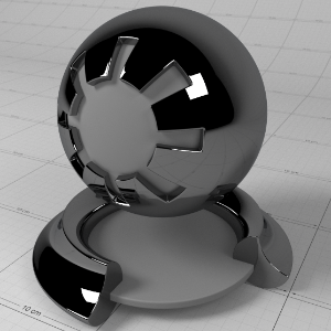
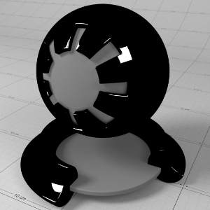
Most dielectric materials have a monochrome reflection, so the simple ' IOR' parameter suffices. Dielectric materials have fairly weak facing reflectivity strength, with IOR values between 1.0 and 3.0, where an IOR value of 1.0 means no reflection and values greater than 1.0 yield stronger reflection.
Below shows an example of how changing the 'IOR' of the material affects the reflectivity. Notice how as the reflection get stronger, the diffuse lighting gets weaker – this is due to energy conservation:
|
|
|
|
|
|
|
IOR 1.0 |
1.25 |
1.5 |
2.0 |
3.0 |
Fresnel Type mode "IOR (Advanced)" In Detail
This advanced mode allows you to set the 'complex' IOR for the material, per red, green and blue channel. Complex IOR consists of an ' IOR' value and an ' Absorption 'k'' coefficient. The scientific values to use can seem non-intuitive for conductors, but can be found at this website: http://refractiveindex.info/, where you can use wavelength of 0.65 for red, 0.55 for green and 0.45 for blue to compute the IOR and k values. Note that dielectric materials should always set the ' Absorption 'k'' coefficients to (0.0, 0.0, 0.0).
This mode is particularly useful for metals, which typically have colored reflectivity and exhibit a slight color shift around the silhouette of the object due to absorption.
If you are not comfortable with working with 'complex' IOR, then we recommend you use the "
Color+Edge Tint" option to define the Fresnel reflectivity instead.
Below are examples of metal materials and their complex IOR values:
|
|
|
|
|
|
|
Aluminuium
|
Copper
|
Gold
|
Iron
|
Two-tone
|
This mode can also be used for dielectric materials that have tinted reflections, by simply setting different IOR values for each red, green and blue channel. For example, to get a pure red tint you can use the following IOR (1.5, 1.0, 1.0).
To achieve this without IOR per color channel, you would simply use the reflection 'Color' to tint the entire reflection. However, for physical correctness, the perpendicular reflectivity for dielectrics should always shift to white, which is not possible using the simple tinting method.
Below shows a comparison between tinted dielectric reflection using Fresnel complex IOR/Reflectivity control and the old-school 'Color' tint. The diffuse component is black, to highlight the reflectivity color; you can see that when using complex IOR, the reflectivity color shifts to white:
|
|
|
|
No color tint, complex IOR
|
Color tinted, simple IOR
|
Absorption (k)
The absorption coefficients for complex IOR materials when using "IOR (Advanced)" Fresnel.
This is primarily for metals and should be 0.0 for dielectrics.
Reflectivity
The facing reflection color of the Fresnel effect when using "Color + Edge Tint" or "Metalness".
Metalness
The 'Metalness' weight. This value ranges between 0.0 and 1.0, where 0.0 means it is a dielectric material that uses the 'Reflectivity' color to control the reflectance and 1.0 means it is a fully reflective metal material that uses the diffuse/base color to control the color of the metal. Values between 0.0 and 1.0 are a blend between the two types of material.
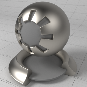
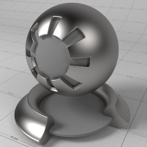
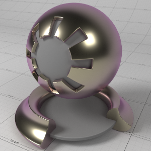
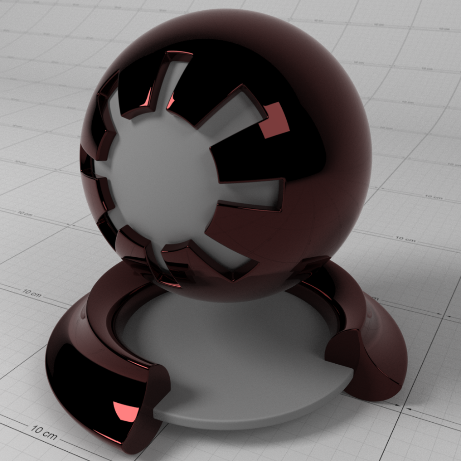
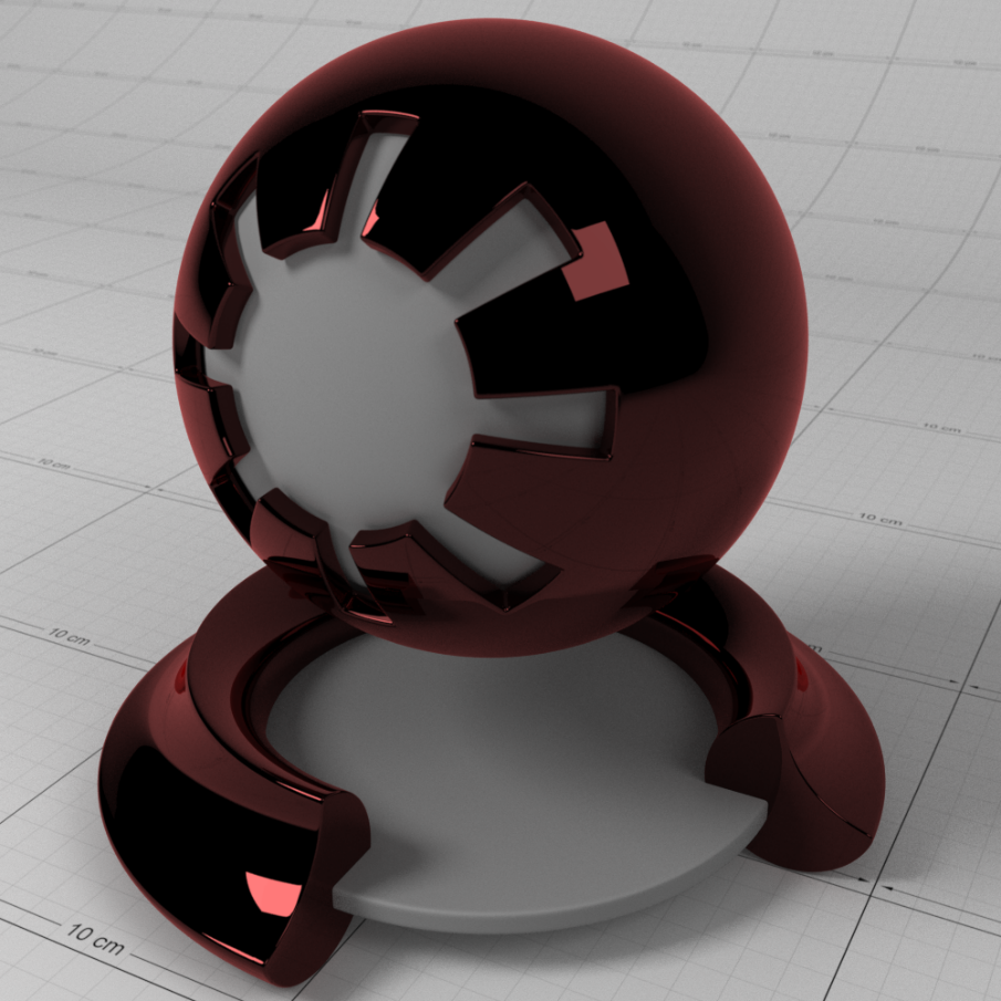
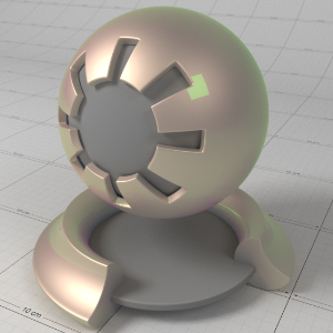
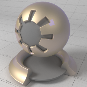
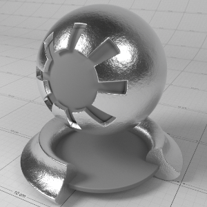
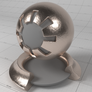
Fresnel Type mode "Metalness" In Detail
This is an artist friendly control made popular by 'Physically Based Rendering' (or 'PBR' for short) principled materials of Unreal, Substance and Disney. The ' Metalness' parameter allows you to blend between a non-metal (i.e. dielectric) material and a purely metal material. When the ' Metalness' value is 0.0, the ' Diffuse Color' defines the diffuse lighting color and the ' Reflectivity' color defines the facing reflectivity – the properties common for dielectric materials. For most dielectrics the ' Reflectivity' color should be no greater than (0.04, 0.04, 0.04), which is actually the hard-coded default value used by Substance and Unreal. When the ' Metalness' value is 1.0, the material is fully reflective, like a metal, with the ' Diffuse Color' interpreted as a 'base color' defining the color of the metal reflection. A ' Metalness' value of 1.0 also means diffuse lighting is disabled and the dielectric 'Reflectivity' color is ignored. When the ' Metalness' value is between 0.0 and 1.0, the material is a blend between the 'dielectric' properties and the 'metal' properties.
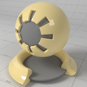
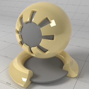
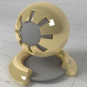
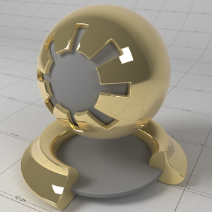
Below shows an example of a material with different 'Metalness' values. Here you can see the effect of the diffuse color (0.944, 0.776, 0.372) as the material becomes more 'metal' as 'Metalness' increases:
|
|
|
|
|
|
|
Metalness: 0.0 |
0.25 |
0.5 |
0.75 |
1.0 |
Metal Edge Tint
The edge shift tint of the Fresnel effect when using "Color + Edge Tint" Fresnel.
This is primarily for metals and should be black for dielectrics.
Fresnel Type mode "Color + Edge Tint" In Detail
This mode offers an artist friendly way to set complex reflectivity values using colors, without requiring knowledge of the non-intuitive complex IOR values. It is primarily useful for conductors/metals, which have colored facing reflectivity and a slight color shift towards the perpendicular reflection, but it can also be used for dielectric materials too.
For further reading you can see the paper here: http://jcgt.org/published/0003/04/03/paper.pdf
The idea is simple; the ' Reflectivity' color is the facing reflectivity strength, with most dielectric materials falling below (0.04, 0.04, 0.04) and conductors/metals considerably higher (0.5, 0.5, 0.5). The ' Metal Edge Tint' controls the color shift bias around perpendicular reflections. For metals, a general rule of thumb is that the ' Metal Edge Tint' should have a similar hue to the ' Reflectivity' color, only brighter. For dielectric materials, ' Metal Edge Tint' should always be black (0.0, 0.0, 0.0).
For perfect mirror reflectivity you can set both the 'Reflectivity' and 'Metal Edge Tint' to white.
Below are examples of metals materials and their 'Reflectivity' and 'Metal Edge Tint' colors:
|
|
|
|
|
|
|
Aluminium |
Copper |
Gold |
Iron |
Two-tone |
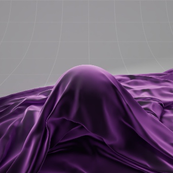
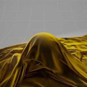
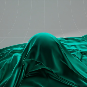
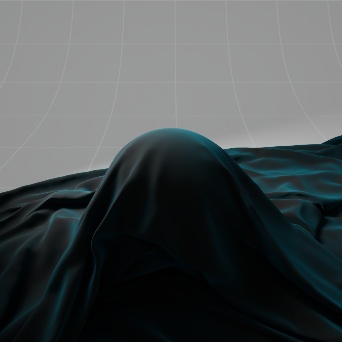
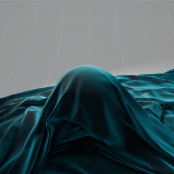
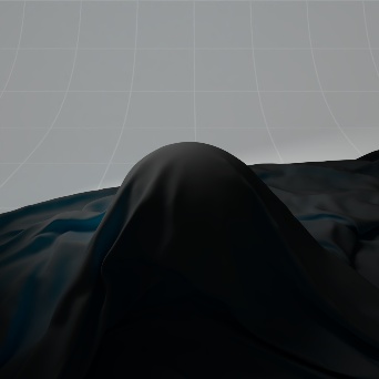
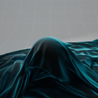
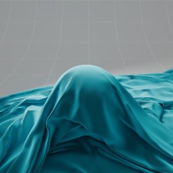
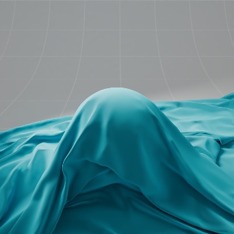
Sheen
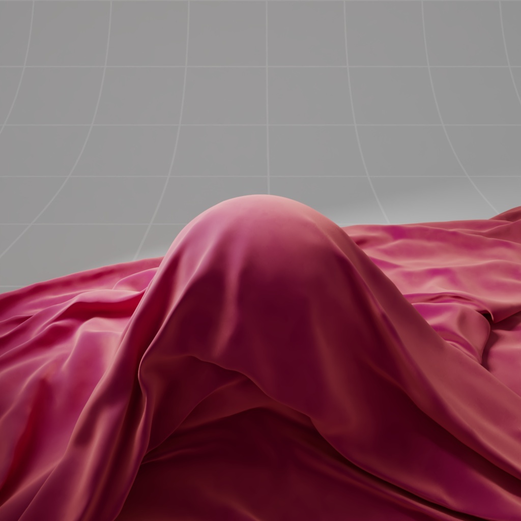
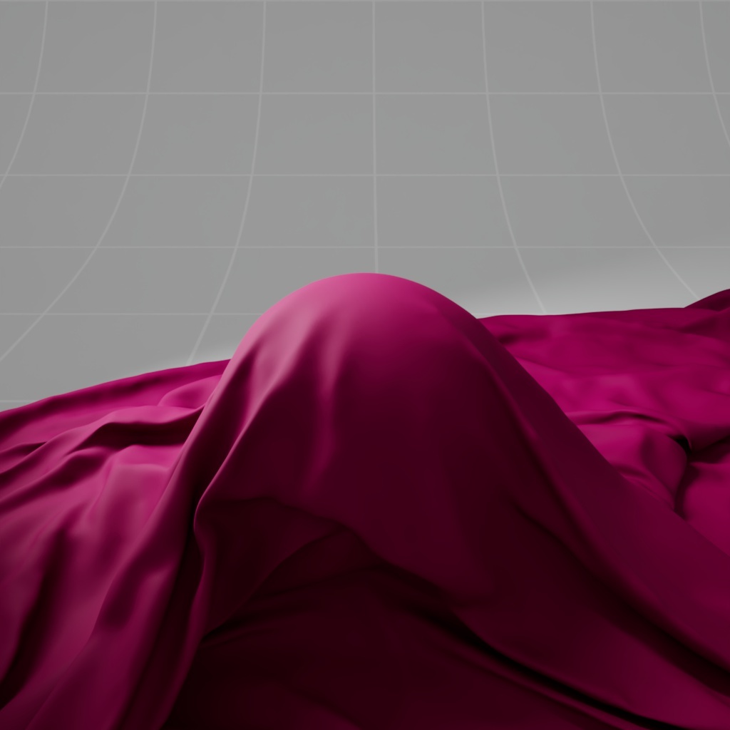
The sheeneffect can be used to simulate a soft backscatter effect commonly seen on fabrics like velvet or satin.
|
|
|
|
Cloth with Sheen |
Cloth without Sheen |
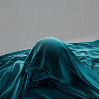
Color
This is the color tint of the sheen.
|
|
|
|
|
|
Sheen Color: Blue |
Purple |
Yellow |
Teal |
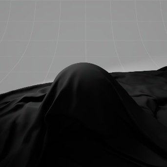
Weight
This is a multipler of the sheen tint. When 0.0 the sheen effect is disabled.
|
|
|
|
|
|
Sheen Weight: 0.0 Sheen Color: Blue |
0.1 |
0.5 |
1.0 |

Roughness
This controls the roughness of the sheen reflection, higher values result in a softer look.
|
|
|
|
|
|
|
Sheen Roughness: 0.0 |
0.1 |
0.2 |
0.5 |
1.0 |

Samples
The higher the sheen's roughness the softer the reflection will be and will need more samples to get a clean "grain-free" result. Higher sheen sample values will reduce any potential grain issues but will take longer to render and vice-versa.
Refraction / Transmission
Color
This is the refraction tint.
To be physically correct, when used in conjunction with sub-surface scattering or sub-surface attenuation, this should be white.
Weight
This is a multiplier of the refraction tint. When 0.0 refraction transparency is disabled.
Roughness
This is the roughness of the refraction rays.
Note that for physical correctness, the perceived roughness effect is affected by the Index of Refraction (IOR) which determines how much rays bend. This means an IOR of 1.0 would yield no roughness effect, whereas larger IOR values yield a stronger roughness effect.
To decouple this dependence on the IOR for the roughness, please see the "Decouple IOR from roughness' option under the 'Advanced' materials options tab.
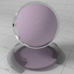
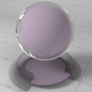
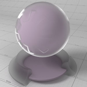
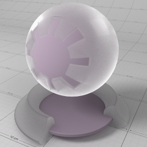
Refraction and Roughness in Detail
When light is reflected by a surface, any energy that is not reflected is transmitted. This remaining transmission energy can be refracted or absorbed and scattered. Because of this, physically correct refractions share the same roughness and ray-bending through IOR properties as the reflections. The ' Link to Reflection' option ensures this physical correctness.
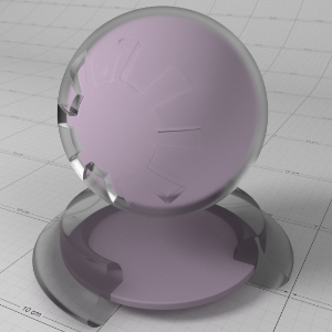
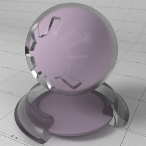
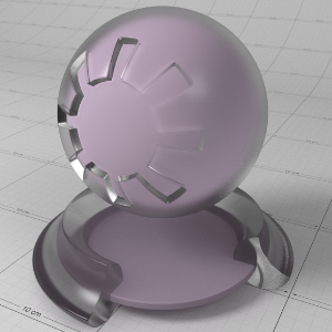
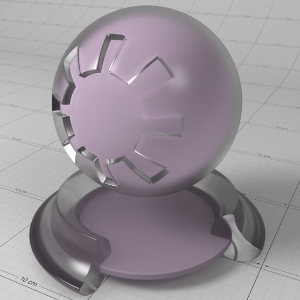
Below shows the effect of roughness on a reflective and refractive glass material with an IOR of 1.51 and with the 'Link to Reflection' option enabled to create a frosted glass effect. Notice how as roughness increases, reflectivity decreases, the glass appears more frosted and energy starts to get lost:
|
|
|
|
|
|
|
Roughness: 0.0 |
0.25 |
0.5 |
0.75 |
1.0 |
If you desire full control over the roughness and IOR of the refraction, simply un-check the 'Link to Reflection' option.
Below shows the effect of roughness on a reflective and refractive glass material, with the 'Link to Reflection' option disabled. To demonstrate, reflection roughness is 0.0, so you can clearly see the reflection remains sharp while the glass appears frosted with a refraction roughness of 0.25:
Below shows the effect of 'IOR' on a non-rough material, where increased IOR bends the rays more. To demonstrate the effect of ray bending, the refraction color is tinted. Noticed how with increased IOR, the more warped the transparency appears and the stronger the reflections appear:
|
|
|
|
|
|
|
IOR: 1.0 |
1.01 |
1.05 |
1.1 |
1.2 |


Below shows the effect of 'IOR' on a rough material. The roughness is fixed at 0.25. See how the perceived roughness changes with IOR - this is physically correct and due to micro-facet theory. Also notice that with an IOR of 1.0 there is no reflection and no refraction:
|
|
|
|
|
|
|
IOR: 1.0 |
1.1 |
1.2 |
1.3 |
1.4 |
Although physically correct, the notion that IOR affects the appearance of roughness can be confusing and non-intuitive. For more control you can decouple the IOR from roughness using the 'Decouple IOR from Roughness' option found in the 'Advanced' tab.
Below shows the effect after roughness has been decoupled from IOR, with a fixed low IOR of 1.05:
|
|
|
|
|
|
|
Roughness: 0.0 |
0.25 |
0.5 |
0.75 |
1.0 |

As with reflection, rougher surfaces require more samples to clean up noise at the expense of rendering times.
Samples
Blurry refractions (when "Roughness" is greater than 0.0) and dispersion will need multiple samples to get a clean "grain-free" result. Higher numbers will reduce any potential grain issues but will take longer to render and vice-versa.
IOR
This is the Index of Refraction, which determines how much refractive rays bend when entering a medium. A value of 1.0 means no ray bending. Values should typically be between 1.0 and 2.0 for common dielectric materials.
Link to Reflection
This option means the "roughness" and "IOR" values are the same as the base reflection. This is ideal for physically-correct refraction which dictates that whatever light is not reflected can be refracted. To specify different "roughness" and "IOR" values for refraction, simply un-check this option.
Dispersion
This controls how much the red, green and blue light separates for the dispersion rainbow effect. Values are in units of 'abbe'. A value of 0.0 is an invalid value for 'abbe' and disables the effect. Common dielectric materials have values between 20 and 70, with lower values yielding a stronger separation effect.
Dispersion in Detail
Some refractive materials exhibit an effect called dispersion, which is when light wavelengths separate based on the index of refraction of the surface for each wavelength. This creates the well-known prism rainbow effect.
The 'Dispersion' parameter allows you to specify the strength of the separation effect, in units of abbe. Dispersion is a subtle effect and common dielectric materials have values between 20 and 70, with lower values yielding a stronger separation effect. A value of 0.0 is an invalid abbe and disables the effect.
Below shows the effect of the 'Dispersion' parameter for various values on a glass material:
|
|
|
|
|
|
|
Dispersion: 1.0 |
5.0 |
10.0 |
20.0 |
30.0 |
Thin Walled
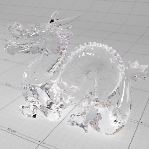
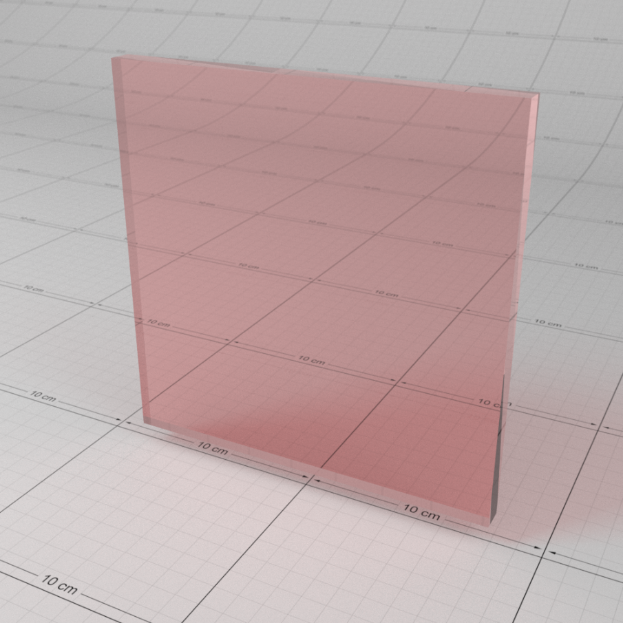
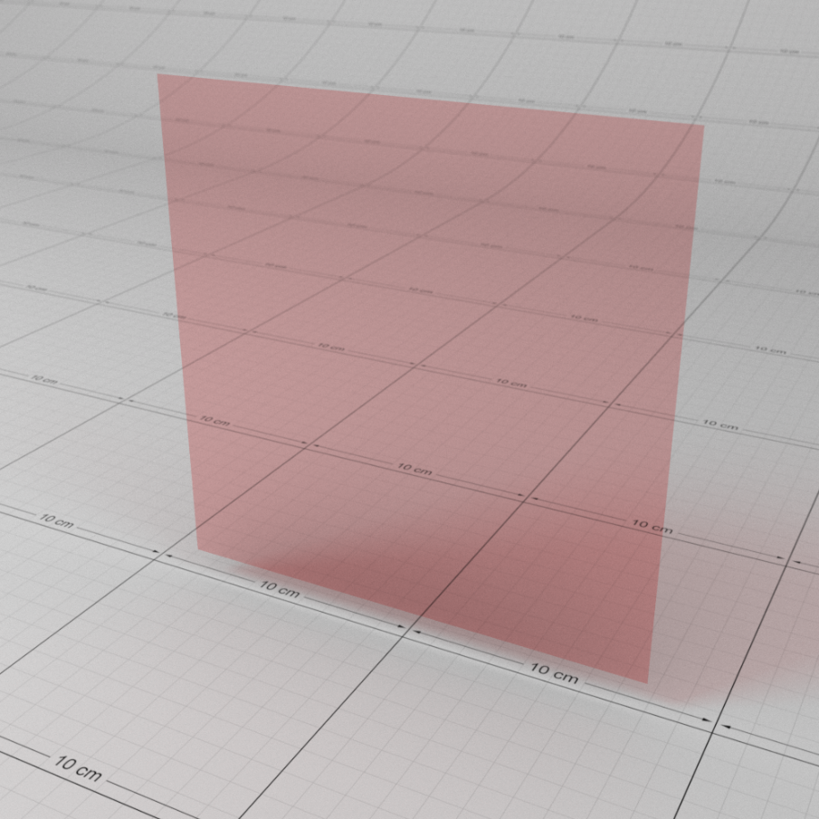
This option is useful for thin refractive materials such a pane of glass, where the ray-bending effect is not noticeable and modeling actual object thickness is not worth it. When this option is enabled, refraction rays will enter and immediately exit the medium without bending the rays.
Sub-surface attenuation and dispersion effects are disabled when this option is enabled.
Thin Transparent Materials in Detail
The 'Thin Walled' option is available for rendering thin transparent objects that don't actually have modelled thickness, such as a pane of glass. For very thin objects, refractive rays will not travel enough of a distance inside the object before exiting to show any noticeable bending effect. Enabling this option preserves the reflection Fresnel effect while internally disabling any medium interface transition math that would allow rays to bend.
Below shows an example of a pane of glass with no thickness and the 'Thin Walled' option enabled, compared to a very thin pane of glass with modelled thickness. You can see there's no noticeable ray bending difference:
|
|
|
|
Thin Walled: disabled |
Thin Walled: enabled |
Sub Surface Single Scattering
These options allow you to describe the effect on transmitted light rays as they travel through a medium. All materials (except perfect, un-tinted glass) exhibit an amount of 'attenuation', where light is absorbed the deeper it travels through the medium. Denser materials have a stronger attenuation effect. Also attenuation is described for each red, green and blue channel, which indirectly affects the color of the medium. A good example of this effect is seen in tinted glass.
On top of attenuation, some mediums exhibit an amount of single scattering. Scattering gives the medium a foggy, milky quality which adds an extra amount of realism. Typical materials that are a good example of scattering are murky liquids such as milk, coffee, wine and beer.
Note that scattering can also affect light attenuation (see 'Attenuation Units') and render time.
Attenuation Units
This option allows you to choose how you want to specify the sub-surface attenuation effect.
- "Transmittance" is essentially the sub-surface color, with darker colors for denser materials. It is used to describe the absorption of light and is independent of attenuation due to any scattering.
- "Extinction" uses scientific units to describe the sub-surface attenuation effect due to both light absorption and scattering. Use this mode for more flexible control of the scattering intensity.
Transmittance Color
When in 'Transmittance' attenuation mode, describes the sub-surface attenuation color. A color of black means full light absorption, yielding a solid material, while a color of white means light rays will pass right through without being absorbed. Dark colors can be used to describe denser materials.
Absorption Scale
When in 'Transmittance' attenuation mode, acts as a scale of the absorption effect, with a value of 0.0 meaning no absorption and larger values meaning stronger absorption and thus denser-looking materials.
Extinction Coeff
When in 'Extinction' attenuation mode, describes the attenuation strength due to both absorption and scattering. These are scientific units, where lower values mean a less dense-looking material, and 0.0 meaning no attenuation at all.
Extinction Scale
When in 'Extinction' attenuation mode, acts as a scale of the 'Extinction Coeff' values to allow quick control over the density of a material.
Scatter Coeff
These are scientific units that describe the strength of the scattering affect for the red, green and blue channels and hence its color.
When in "Transmittance" 'Attenuation Units' mode, the scatter values also affect attenuation, so larger scattering values will make the medium appear more 'cloudy'.
When in "Extinction" 'Attenuation Units' mode, the scatter values act more like a color multiplier of the scattering effect. This allows you to easily scale up the brightness of the scattering effect which may break physical correctness, but also gives you extra flexibility to describe more exotic mediums.
Scatter Scale
This scales the 'Scatter Coeff' values. A value of 0.0 disables the scattering effect.
Phase
This describes the anisotropy of the scattering effect, for forward and back scattering. Forward scattering requires values between 0 and 1, which means rays will scatter away from the light source. Back scattering requires values between -1 and 0 which means rays will scatter back towards the light source.
Samples
This is the maximum number of samples shot for single scattering rays. More samples will mean less noisy looking single scattering, but can affect rendering performance.
Sub-Surface Light Transmission Attenuation and Scattering
The 'Attenuation Units' option allows you to define the light attenuation and scattering properties for a sub-surface medium in two ways; "Transmittance" and "Extinction".
The "Transmittance" mode is recommended for materials such as tinted glass that have no scattering, offering an intuitive method to control the attenuation of light through the sub-surface.
The "Extinction" mode uses scientific values and is recommended for fuller control over the scattered light color.
Attenuation Units Mode "Transmittance" In Detail
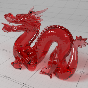
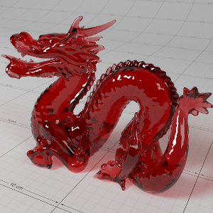
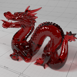
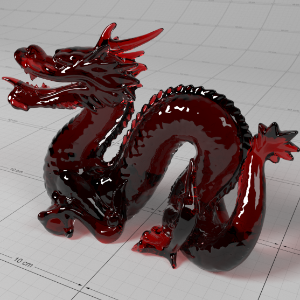
This mode allows you to specify a 'Transmittance Color', i.e. the color of the light transmission ray after it has been absorbed by the material having travelled 1.0 unit of distance. This in turn determines a sub-surface absorption coefficient which can then be scaled using the ' Absorption Scale' parameter. When absorption is low, light will travel further through the sub-surface before it is extinguished, resulting in a more transparent looking material. Conversely, higher absorption means light will travel less before it is extinguished, giving a material a more solid, darker appearance.
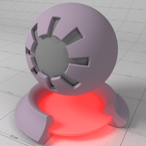
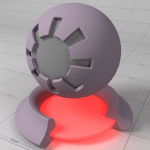
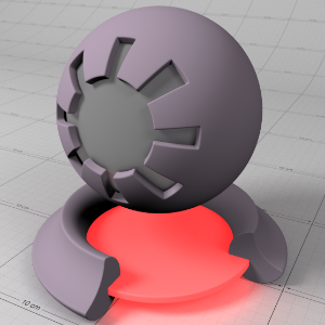
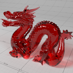
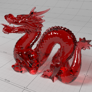
Below shows the effect of 'Transmittance' on a glass material to create a red-tinted solid glass effect. Note how an 'Absorption Scale' of 0.0 disables the light attenuation effect. Also note how increasing the 'Absorption Scale' makes the glass look denser and thus darker in the thicker areas of the object:
|
|
|
|
|
|
|
Absorption Scale: 0.0 |
0.5 |
1.0 |
2.0 |
4.0 |
To enable sub-surface scattering the 'Scatter Coeff' values and 'Scatter Scale' must be greater than 0.0. In Transmittance attenuation mode, the 'Scatter Coeff' and 'Scatter Scale' defines the color of the scattered light and affects the overall attenuation of the light as it is scattered through the medium. The attenuation effect (or loss of energy) due to scattering is physically correct to ensure energy conservation.
Below shows an example of just the scattering effect with no 'Transmittance Color' absorption affecting the attenuation of light; all attenuation is due to the scattering coeff. This is fairly close to real liquid materials that have very similar scattering and extinction coefficients. Notice that although the scatter coeff color is close to red, due its effect on attenuation the color of the light as it attenuates through the object tends towards the inverse of red, i.e. cyan. Also notice that with increased scattering coefficient strength, the material appears more diffuse/solid:
|
|
|
|
|
|
|
Scatter Scale: 1.0 |
2.0 |
4.0 |
8.0 |
16.0 |

If you want to achieve a scattering color that is close to the color of the 'Scatter Coeff', you need to compensate for the coeff's effect on attenuation.
Below shows an example of compensating for the scatter coeff's effect on attenuation by tweaking the 'Transmittance Color' to red, to essentially knock out the cyan color. Notice that the addition of 'Transmittance Color'-driven absorption makes the material appear denser – this is because light is now being attenuated by both absorption and scattering:
|
|
|
|
|
|
|
Scatter Scale: 0.0 |
0.25 |
0.5 |
1.0 |
2.0 |
Attenuation Units Mode "Extinction" In Detail
This mode allows you to specify the light attenuation effect and scattering with more control of the scattering color; in this mode it is assumed that all attenuation due to absorption and scattering is baked into the ' Extinction Coeff' values. The ' Extinction Scale' parameter is a simple scale of the coefficients, where lower values mean a more transparent material and higher values result in a more solid-looking material.
Note that 'Extinction Coeff' values are in scientific units and do not actually represent colors, they represent the rate at which the red, green and blue components of the light ray are attenuated.
Below shows an example different values of 'Extinction'. Note how with an extinction color of red, the attenuated light rays color tends towards cyan; this is for the same reason the scatter example above tended towards cyan with low scattering values:
|
|
|
|
|
|
|
Extinction Scale: 1.0 |
2.0 |
4.0 |
8.0 |
16.0 |
To enable sub-surface scattering the ' Scatter Coeff' values and ' Scatter Scale' must be greater than 0.0. In Extinction attenuation mode, the ' Scatter Coeff' defines the color of the scattered light, by simply tinting the scattered light. Because it does not affect attenuation, increasing the ' Scatter Coeff' values, or ' Scatter Scale', will increase the intensity of the scattered light.
To be physically correct, Scatter Coeff and Scatter Scale should not be greater than the 'Extinction Coeff' values, but it can be useful if the resultant image is too dark for your taste or you want to create interesting effects.
Below shows an example of using similar coefficients to above examples, with increased scattering scales to increase the light intensity inside the sub-surface:
|
|
|
|
|
|
|
Scatter Scale: 4.0 |
8.0 |
16.0 |
32.0 |
64.0 |

The simplest approach is to use the same 'Extinction' and 'Scatter' values to get the most predictable results. For example, if you want to make the scattered material more transparent, reduce the 'Extinction' and 'Scatter' values, and if you want to make the scattered material appear more opaque and 'diffuse' increase both the 'Extinction' and 'Scatter' values.
Below shows examples of increasing the 'Extinction' and 'Scatter' values to make the material less translucent and more dense or opaque looking. Note that with both the extinction and scatter values being the same, the results are the same as the first scatter example:
|
|
|
|
|
|
|
Scatter Scale: 1.0 |
2.0 |
4.0 |
8.0 |
16.0 |
If you want to achieve a scattering color that is close to the color of the 'Scatter Coeff', you need to compensate for the 'Extinction Coeff''s effect on attenuation by making it grey-scale.
Below shows an example of achieving a lighting result that is representative the 'scatter coeff' color. See how higher 'Scale' values make the object less transparent and denser:
|
|
|
|
|
|
|
Scatter Scale: 0.25 |
0.5 |
1.0 |
2.0 |
4.0 |

Single-Scattering Performance Considerations
Single scattered materials can vary in density. Very densely scattered materials can look 'solid', while non-dense materials such as some liquids will not appear 'solid'. Choosing whether to enable transparency/refraction on a single-scattered material depends on how solid the scattering result looks and the shape of the geometry. Also a very important consideration is that transparent materials can be slower to render, particularly with refractive materials that have an IOR greater than 1.0, which allow the refraction rays to bend and potentially bounce around inside the sub-surface before they exit.
Below shows a comparison between a relatively dense sub-surface scattering 'opaque' material and 'transparent' material. Note that because light does not exit the opaque material, the cyan tint present on the transparent material around the thin parts gets lost, otherwise the results are very similar. Also notice that with increased density, the difference becomes less apparent:
|
|
|
|
|
|
Refraction Weight: 1.0 (transparent)
|
0.0 (opaque) |
1.0 (transparent)
|
0.0 (opaque) |

Phase in Detail
The 'Phase' parameter controls the anisotropy of the scattering effect, describing how the lighting will bounce around inside the medium and get scattered. A phase of 0.0 means that the lighting will bounce around more and will appear more diffuse. Values greater than 0.0 produce what is known as "forward scattering". Forward scattering means the lighting doesn't bounce around in the medium as much and is mostly visible after travelling through the medium, away from the light source. On the other hand, negative numbers will produce "backward scattering' which means that scattered light will mostly be bounced out of the medium back towards the light source.
Below shows an example of how phase affects the resultant scattered lighting. The light is shining towards the side of the dragon, away from the camera, and the Scatter Coeff strength is exaggerated to highlight the effect:
|
|
|
|
|
|
|
Phase: -0.8
|
-0.4 |
0.0 |
0.4 |
0.8 |
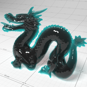
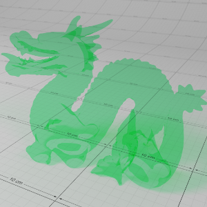
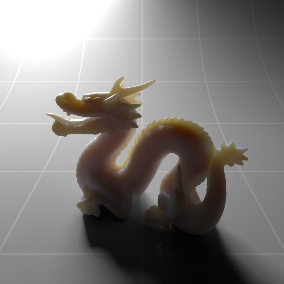
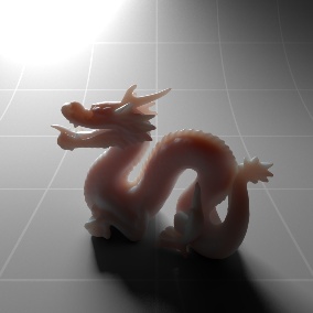
Sub-Surface Multiple Scattering
In addition to sub-surface single scattering, the Redshift Material also supports sub-surface multiple scattering. Multiple scattering means that scattered light gets bounced around inside the medium multiple times, which produces a softer effect than single scattering alone.
These options allow you to define the sub-surface multiple scattering effect (similar to the Redshift SubSurfaceScatter and Redshift Skin material shaders). The effect can be controlled for up to three layers. Most materials require only one layer to get plausible looking results, however complex materials such as skin require multiple layers to accurately emulate the scattering of light within the sub-surface.
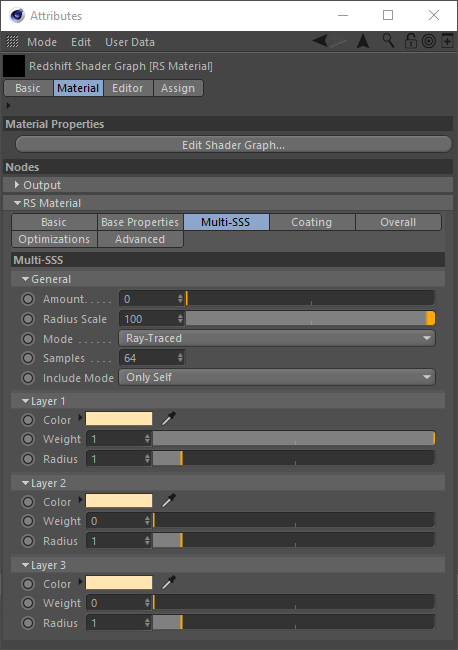
General
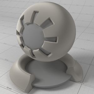
Amount
The sub-surface multiple scattering amount. When 0.0, the material will be pure diffuse, with no sub-surface scattering. When 1.0, the material will be fully sub-surface scattered, with no diffuse. Values in-between yield a blend of the two.
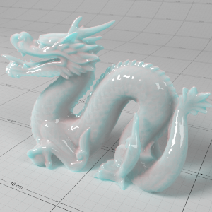
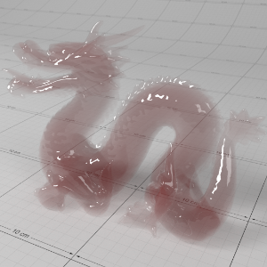
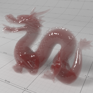
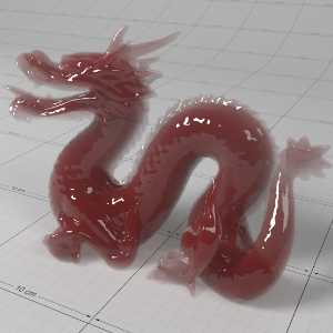
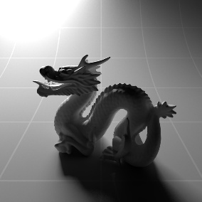
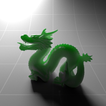
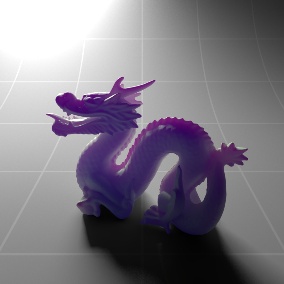
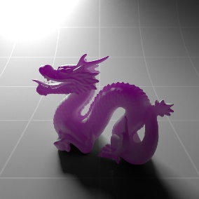
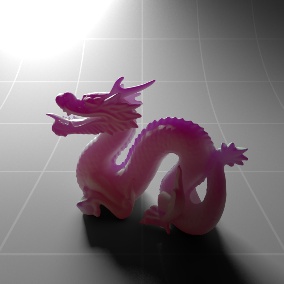
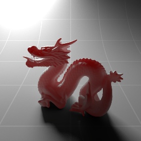
To enable the multiple scattering effect, you must first set the 'Amount' parameter to a value greater than 0.0. When the 'Amount' value is 1.0, the material will be fully sub-surface scattered, with no diffuse lighting. Values between 0.0 and 1.0 result in a blend of sub-surface scattering and diffuse lighting. For the following examples the light is positioned behind the object in order to highlight the sub-surface effect.
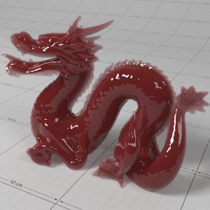
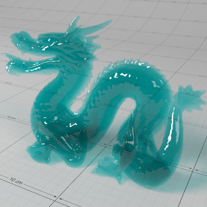
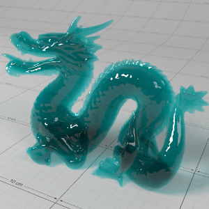
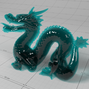
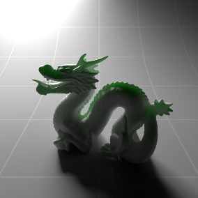
Below shows the increasing sub-surface translucency effect of a jade material by increasing the 'Amount' parameter:
|
|
|
|
|
|
|
Amount: 0.0 |
0.25 |
0.5 |
0.75 |
1.0 |


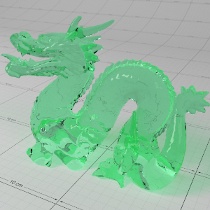
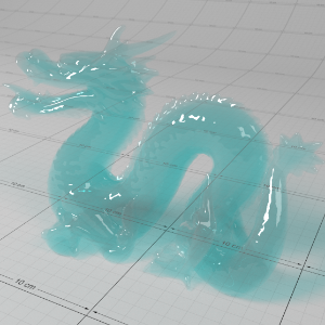
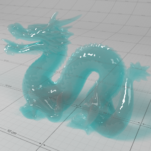
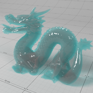
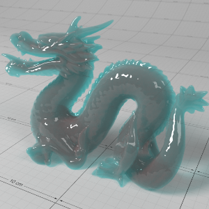
Radius Scale
The scale controls how soft or hard the scattering effect will be. Higher numbers make the effect softer. This value is multiplied into the "Layer Radius" parameter explained below. A radius scale of 0 means no scattering effect.
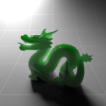
The 'Radius Scale' parameter allows you to control how deep the light rays go as they are scattered. Higher values result in a more translucent or 'soft' appearance, with lower values resulting in a more diffuse or 'hard' appearance. Tuning this value is also useful if your scene units don't match the material well.
Note that internally Radius Scale acts as a multiplier of all the 'Layer Radius' values.
Below shows how increasing the 'Radius Scale' can affect the overall translucency 'softness' by decreasing the density and allowing more light through:
|
|
|
|
|
|
|
Radius Scale: 0.0 |
1.0 |
2.0 |
3.0 |
4.0 |


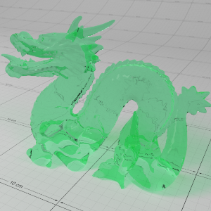
Mode
- Point-Based
- Ray-Traced
You can use either point-based or ray-traced multiple sub-surface scattering in Redshift and both have their own advantages and disadvantages. In quite a few cases the techniques should look similar to each other but there are situations where the differences will be readily apparent, this is primarily due to the normalization of light that occurs when using point-based mode. Ray-traced mode does not normalize the light which can lead to differences that are most notable on thin objects or objects with more surface detail.
If your scene is setup to use point-based SSS shaders and you render in progressive mode it will automatically use ray-traced SSS during progressive renders. This way you can actually see the SSS effect in progressive mode (and not just the diffuse texture) and tweak settings interactively - while still using point-based for the final (bucket) rendering.
Please note that due to the differences in the two modes that the final result can differ when comparing progressive ray-traced SSS to the bucket rendered point-based SSS.
Point-Based
-
Faster and smoother
-
Less detailed / accurate
-
Does not work in progressive mode
-
Requires a “prepass” stage
-
Higher chance of flickering in difficult lighting situations.
-
Not possible to isolate SSS effect on a particular object which can result in unnecessary “light bleeding” artifacts.
Ray-Traced
-
Slower and noisier
-
More detailed / accurate
-
Works in progressive mode
-
The higher the scatter radius the more samples are needed for clean results.
-
Possible to isolate SSS effect between objects or have it affect all objects. Please see here for more info.
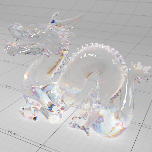
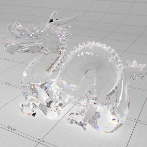
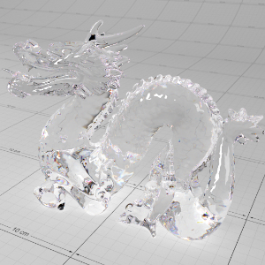
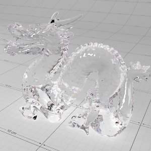
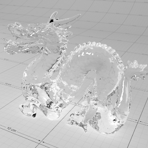
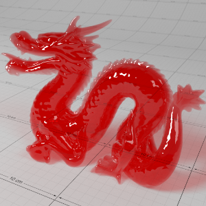
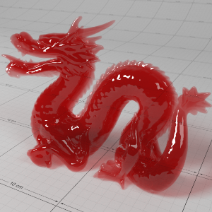
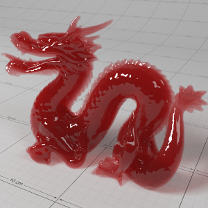
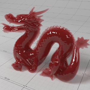
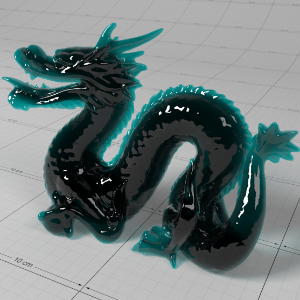
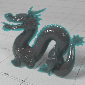
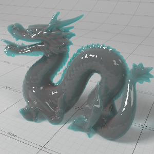
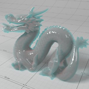
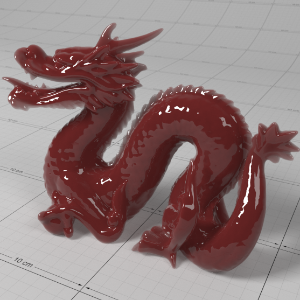
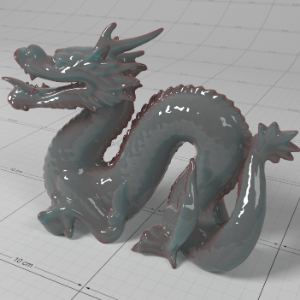
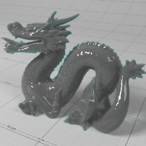
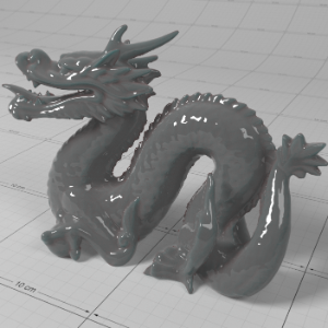
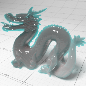
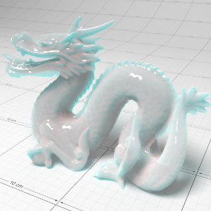
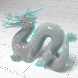
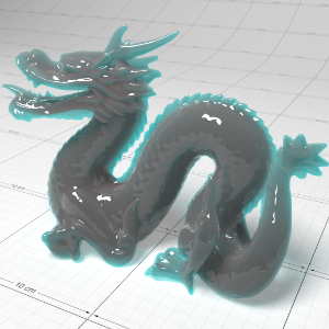
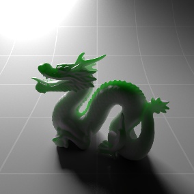
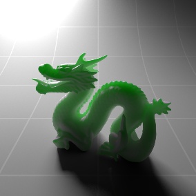
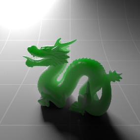
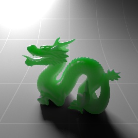
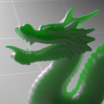
In the examples below note the added definition and detail in the face and around the fins of the dragon model in the ray-traced mode.
|
|
|
|
|
|
Mode: Point-Based Render Time: 13s |
Ray-Traced 1m 11s |
Point-Based 15s |
Ray-Traced 2m 47s |

Samples
This controls the number of samples cast for Multiple Sub-Surface Scattering rays. Higher numbers will reduce noise issues but will take longer to render.
Ray-Traced only
|
|
|
|
|
Samples: 128 |
512 |
4096 |


Include Mode
- All Objects : All other objects participate in the SSS effect.
- Only Self : Contain the SSS effect in the same object only.
Ray-Traced only
Layer 1-3
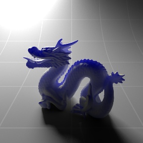
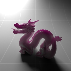
Color
This is the scatter color of the layer, which it tends to the further the light travels within the layer.
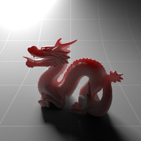
The Layers 'Color' value describes the sub-surface scatter color of the light as it travels within the sub-surface.
Below shows an example of different sub-surface scatter colors. Notice that in this example the diffuse color is white, hence the GI bounce appearing white on the near-side of the dragon:
|
|
|
|
|
|
|
Layer Color: (1.0, 0.0, 0.0)
|
(0.0, 1.0, 0.0) |
(0.0, 0.0, 1.0) |
(0.54, 0.33, 0.12) Whole Milk |
(0.48, 0.17, 0.1) Pink Skin |


Weight
This is the weight of the layer, with larger values meaning the layer will dominate the sub-surface results.
Note for correct energy conservation, the weights for each layer are normalized so the resultant total weight for all layers is always 1.0.
|
|
|
|
|
|
|
Layer 1 Weight: 0.0 Layer 1 Color: (1.0, 0.0, 0.0) Layer 2 Weight: 1.0 Layer 2 Color: (0.0, 0.0, 1.0) Diffuse Color: (1.0, 1.0, 1.0) |
0.5
1.0 |
1.0
1.0 |
1.0
0.5 |
1.0
0.0 |


Radius
This is the distance the light can travel through the object, with larger values producing softer results. A value of 0.0 will produce diffuse-like results.
The Layers 'Radius' value increases the distance which the light can travel within the sub-surface before it is extinguished. Higher values result in a more translucent or 'soft' appearance.
Below shows an example of changing the 'Radius' value for Layer 1 (red color) and Layer 2 (blue color) and how different mixes affect the results:
|
|
|
|
|
|
|
Layer 1 Radius: 0.0 Layer 1 Color: (1.0, 0.0, 0.0) Layer 2 Radius: 1.0 Layer 2 Color: (0.0, 0.0, 1.0) Diffuse Color: (1.0, 1.0, 1.0) |
0.3
1.0 |
1.0
1.0 |
1.0
0.3 |
1.0
0.0 |
Important Considerations for Sub-Surface Multiple Scattering
When using multiple layers to define more complex sub-surface materials such as skin, note that the weights for each layer are normalized before they are applied to the final sub-surface result. This means that if you are using 3 layers, each with a weight of 1.0, then the normalized weight for each layer will be 1.0 / 3.0.
The final sub-surface result of all layers is tinted by the 'Diffuse Color', which essentially describes the 'exit' color of the scattered light. This makes it much easier to texture a surface that uses multiple sub-surface Layers.
For the best performance sub-surface multiple scattering should be used in conjunction with opaque materials.
Coating
These options allow you to define a coating layer over the material, to emulate properties such as varnish, the reflective clear coat of car paint, or slimy and wet surfaces. Additionally, the coating layer has its own bump map input which allows you to define details such as scratches separate from the base of the material, or leave as perfectly smooth.
Since the coating layer covers the entire material, due to energy conservation it will indirectly affect the strength of lighting for the 'base layer' material properties, such as diffuse, reflection, refraction and scattering (see 'Energy Conservation' topic in the 'Advanced' section).
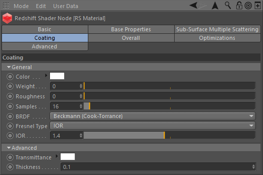
General
Color
This is the reflection tint.
To be physically correct, this should be white and the IOR/Reflectivity for each RGB channel should be used instead to add color.
Weight
This is a multiplier of the reflection tint. Reflections are disabled when this value is 0.0.
Roughness
This is the roughness of the surface reflection. A roughness value of 0.0 means perfectly 'polished', or full glossiness. A roughness value of 1.0 means almost diffuse appearance.
Samples
Blurry reflections (when "Roughness" is greater than 0.0) will need multiple samples to get a clean "grain-free" result. Higher numbers will reduce any potential grain issues but will take longer to render and vice-versa.
BRDF
This allows you to select which reflection model to use;
- "Beckmann (Cook-Torrance)" is a physically-based industry-standard reflection model that accurately represents a wide variety of materials.
- "GGX" is a relatively new model that offers a wide specular tail, making it perfect for difficult to emulate metals such as chrome.
- "Ashikhmin-Shirley" is good for a wide variety of materials and samples efficiently for noise-free results.
Fresnel Type
This allows you to select between different methods of controlling the reflection Fresnel effect;
- "IOR (Advanced)" lets you set the Index of Refraction for each red, green and blue channel. This allows you to control the reflectivity color for both dielectric materials (i.e. non-metals) and metals, while remaining physically correct.
- "Color" is an artist friendly mode that allows you to control the facing reflectivity color, without required complex IOR values.
- "IOR" lets you set a single Index of Refraction value to control reflectivity and is ideal for simple dielectric materials. Dielectric materials typically have an Index of Refraction between 1.0 and 2.0, where 1.0 means no reflectivity and higher values mean stronger reflectivity.
IOR
The index of refraction used to calculate the strength of the Fresnel effect. Consists of three values (for red, green and blue) when using "IOR (Advanced)" Fresnel.
The coating reflection layer shares similar properties to the base reflection (see Reflection for examples of 'BRDF', 'Fresnel Type' and 'Roughness').
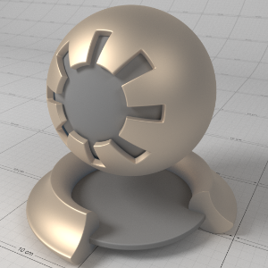
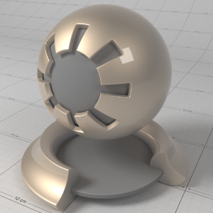
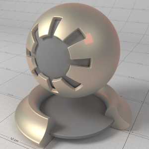
Below shows an example of a clear-coat reflection layer over a very rough metallic 'gold' material. Note that the rectangular specular highlight is clearly defined, compared to the rough base metal reflection. Note that an IOR of 1.0 effectively disables the coat. Also note that with a colored coat you can achieve a nice two-tone effect:
|
|
|
|
|
|
|
Coating IOR (Advanced): |
(1.6, 1.6, 1.6) |
(1.6, 1.01, 1.01) |
(1.01, 1.6, 1.01) |
(1.01, 1.01, 1.6) |
Reflectivity
The facing reflectivity color of the Fresnel effect when using "Color" Fresnel Type.
Advanced
Transmittance
Transmittance color for transmission emulation. A color of white means there will be no transmittance effect. Non-white colors will yield a subtle transmittance color-shift effect around the edges of the object, simulating coating depth.
Thickness
Coating depth scale for the transmission emulation effect. Lower values yield a subtler effect, while larger values yield a stronger transmission effect. A value of 0.0 means the transmission effect is disabled.
Coating has 'Transmittance' and 'Thickness' parameters to emulate absorption of light as it travels through the coating layer before it reflects from the base layer. This can create interesting and more realistic looking coating on materials such as tinted glazing.
Below shows an example of the 'Transmittance' effect with increasing 'Thickness' to accentuate the effect:
|
|
|
|
|
|
|
Thickness: 0.0
|
0.1 |
0.2 |
0.3 |
0.4 |


Bump Map
Plug in your coating bump map here. Coating bump mapping is separate from the base layer, which means you can apply details such as scratches on just the coating, or even leave the coating blemish-free.
By plugging a bump map into the main bump port of the material and leaving the coating bump port empty, you can achieve a more convincing-looking clear coat or varnish effect:
|
|
|
|
Bump in both base and coating port |
No bump in coating port |
Overall
These options are applied to the overall material.
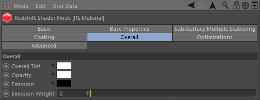
Overall Tint
This is an overall tint for the entire material.
The 'Overall Tint' parameter allows you to tint the entire material after lighting has been calculated. This parameter is also useful if you want to apply additional lighting attenuation from effects such as ambient occlusion, to accentuate shadows around crevices.
Below shows examples of 'Overall Tint'. See how it affects both diffuse lighting and reflections:
|
|
|
|
|
|
|
Overall Tint: (1.0, 0.0, 0.0) |
(0.0, 1.0, 0.0) |
(0.0, 0.0, 1.0) |
(1.0, 1.0, 1.0) |
AO shader |

Opacity
This color describes the overall opacity of the material, with colors closer to white being more opaque. An opacity of black means the material will be fully transparent.
Note that this effect is currently dependent on the global/local refraction trace depth (see Optimizations tab). If you only need cutout transparency you should make use of the Redshift Sprite shader.
Below shows examples of the 'Opacity' of a material. Note that refraction color is the inverse of the opacity color. Grey-scale values are typically used to describe opacity:
|
|
|
|
|
|
|
Opacity: (1.0, 0.0, 0.0) |
(0.0, 1.0, 0.0) |
(0.0, 0.0, 1.0) |
(0.5, 0.5, 0.5) |
(0.25, 0.25, 0.25) |
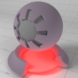
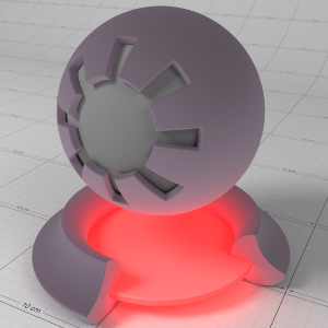
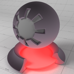
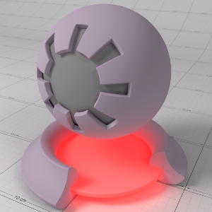
Emission
This is the emissive color of the material.
Emission Weight
This is a multiplier of the emissive color of the material.
Below shows examples of 'Emission':
|
|
|
|
|
|
|
Emission: (1.0, 0.0, 0.0)
|
(0.0, 1.0, 0.0)
|
(0.0, 0.0, 1.0)
|
(0.0, 0.0, 1.0)
|
(0.0, 0.0, 1.0)
|
Bump Map
Connect your overall bump map here.
Optimizations
These options allow you to fine-tune the performance of the material.
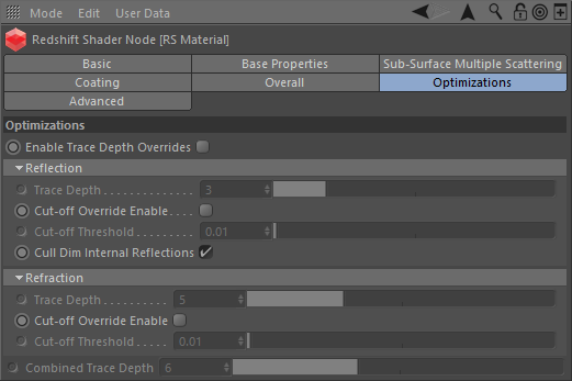
Enable Trace Depth Overrides
This enables the per material Max Reflection and Refraction/Opacity Trace Depth parameters below.
When not enabled, the global trace depth will be used.
Note that when enabled, the override cannot exceed the global trace depth.
Reflection
Trace Depth
This parameter controls the trace depth for reflection rays shot from this material. If the reflection rays of a material are not very defined (meaning: they are blurry because of the roughness parameter or have a low weight), then multiple bounces can be a waste of rendering time. This parameter allows the user to reduce the trace depth and speed up rendering.
Cut-off Override Enable
This parameter allows you to override the global cut-off setting for reflections.
Cut-off Threshold
When the reflections of a material are very dark (because of low "Weight" or "Color" values) they contribute very little to the final image. This parameter defines what is considered "very dark" at which point no more reflection rays will be shot - which will speed up rendering. Scenes containing very strong lights might need this parameter set to very low values such as 0.0001 in order to avoid early termination of tracing which can produce a grain-like effect.
Cull Dim Internal Reflections
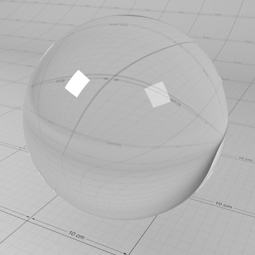
This is a simple, but important performance optimization to prevent rays getting trapped inside objects that are both reflective and refractive. Normally, two rays would be spawned for every surface hit inside the object, one for reflection and one for refraction. If you had a glass object, for example, you would have rays bouncing about, trapped inside the sphere until their max trace depth is reached, potentially adding very little to the overall visual quality if the reflected amount is 'weak'. Having this option enabled turns off reflected rays inside the object. Note that this option does not affect refractive rays that are reflected due to Total Internal Reflection. One caveat of using this option is that hot internal specular reflections will be lost, which is not realistic, but often acceptable. This is enabled by default.
Unless you are modelling materials like lenses that need to look realistic, we recommend you leave this option enabled.
Below shows a comparison between a glass material with the 'Cull Dim Internal Reflections' option enabled/disabled. You can see the hot internal specular reflection is lost with the option enabled, which is not realistic but can be acceptable and renders much faster:
|
|
|
|
Cull Dim Internal Reflections: enabled |
disabled |
Refraction
Trace Depth
This parameter controls the trace depth for refraction rays shot from this material. If the refraction rays of a material are not very defined (meaning: they are blurry because of the roughness parameter or have a low weight), then multiple bounces can be a waste of rendering time. This parameter allows the user to reduce the trace depth and speed up rendering.
Cut-off Override Enabled
This parameter allows you to override the global cut-off setting for refractions.
Cut-off Threshold
When the refractions of a material are very dark (because of low "Weight" or "Color" values) they contribute very little to the final image. This parameter defines what is considered "very dark" at which point no more reflection rays will be shot - which will speed up rendering. Scenes containing very strong lights might need this parameter set to very low values such as 0.0001 in order to avoid early termination of tracing which can produce a grain-like effect.
Combined Trace Depth
This allows you to set a custom combined trace depth for your Redshift material shader.
The legacy setting "Use Combined Trace Depth from Materials" must be enabled in the render settings System tab in order for this setting to work. Otherwise, by default, the Combined Trace Depth value found in the Globals tab will control the max combined trace depth.
Optimization Options In Detail
When the 'Enable Trace Depth Override' option is enabled, the material trace depths defined here are used instead of the global ones. This can be useful for fine-tuning performance on a per material basis where dropped bounces might not be noticed.
When the 'Reflection/Refraction' Cut-off Override is enabled, the cut-off values are used instead of the global ones.
For examples of how to use the trace depths and cut-offs, please see the Material documentation.
Advanced
These options allow you to tune features of the material that are not commonly used.
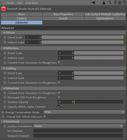
Diffuse / Reflection / Coating
Direct Scale
This parameter allows you to independently scale the weight of direct lighting rays, i.e. diffuse/reflection rays intersecting lights in the scene. Setting this value to 0.0 effectively disables direct lighting.
Indirect Scale
This parameter allows you to independently scale the weight of indirect lighting rays, i.e. GI/reflection rays intersecting surfaces in the scene. Setting this value to 0.0 effectively disables indirect lighting, which can be a useful optimization.
Note that setting this value to 0.0 is equivalent to the 'Specular Highlights Only' option that can be found in other Redshift material shaders, such as Architectural.
Direct and Indirect Scales in Detail
To optionally balance the amount of direct lighting vs indirect lighting, or even cancel direct or indirect lighting altogether, you can adjust the 'Direct Scale' and 'Indirect Scale' for diffuse and reflections.
Note for physically correct results both the 'Direct' and 'Indirect' lighting scales should be 1.0 or the same value.
Below shows an example of scaling down the amount of Diffuse Direct and Indirect Lighting. Diffuse GI is enabled and the base is emissive to highlight the GI indirect lighting effect. Notice how the influence of the direct light diminishes and GI indirect bounce diminishes:
|
|
|
|
|
|
|
Diffuse Direct Scale: 1.0 |
0.75 |
0.5 |
0.25 |
0.0 |
|
|
|
|
|
|
|
Diffuse Indirect Scale: 1.0 |
0.75 |
0.5 |
0.25 |
0.0 |
Below shows an example of scaling down the amount of Reflection Direct and Indirect Lighting. Notice how the influence of the rectangular direct lights diminishes – the lights are very hot so much lower scale values need to be used to see a noticeable effect. Indirect reflection of the surrounding scene requires less aggressive values to see a difference:
|
|
|
|
|
|
|
Reflection Direct Scale: 1.0 |
0.2 |
0.1 |
0.05 |
0.0 |
|
|
|
|
|
|
|
Reflection Indirect Scale: 1.0 |
0.75 |
0.5 |
0.25 |
0.0 |
Convert from Glossiness to Roughness
This option is useful when you have legacy textures that drive material roughness using the 'glossiness' convention - i.e. where a glossiness value of 0.0 means maximum roughness and a value of 1.0 means perfectly smooth. Enabling this option essentially inverts any inputs to 'roughness' parameters, to convert from glossiness to roughness.
Refraction
Convert from Glossiness to Roughness
This option is useful when you have legacy textures that drive material roughness using the 'glossiness' convention - i.e. where a glossiness value of 0.0 means maximum roughness and a value of 1.0 means perfectly smooth. Enabling this option essentially inverts any inputs to 'roughness' parameters, to convert from glossiness to roughness.
Decouple IOR From Roughness
Physically correct refraction roughness due to micro-facet theory is affected by the Index Of Refraction, where higher IOR values can yield a rougher appearance and an IOR of 1.0 would yield no roughness at all. Enabling this option ignores the IOR when generating rough refraction rays, which can result in a more predictable effect, even though it is not physically correct.
See this example for the 'Decouple IOR from Roughness' option.
Shadow Opacity
This option allows you to tune the shadow opacity of transparent materials. A value of 0.0 means the transparency of the shadow is unaffected, while a value of 1.0 means the shadow will be fully opaque and black. This option can be useful when used in conjunction with photon caustics, when a darker shadow can prevent photon caustics from appearing washed out.
Note that setting this value to 1.0 is equivalent to enabling the 'Enable Refractive Caustics' option found on the Redshift Architectural material shader.
Below shows the effect of increasing the 'Shadow Opacity' for a tinted glass material. The shadow is from area lighting and is quite soft; as the opacity increases the shadow loses its reddish tint and the photon caustics stand out more:
|
|
|
|
|
|
|
Shadow Opacity: 0.0 |
0.25 |
0.5 |
0.75 |
1.0 |


Opacity Affects Alpha Channel
By default with this option enabled, refraction and opacity will affect the alpha channel. So if your object has 50% transparency your alpha will reflect that with 50% alpha.
Disable this parameter if you want your transparent objects to have a solid alpha.
Block Volumes in Sub-Surface Mediums
Volumetric structures, such as clouds, are not rendered where they lie within a Subsurface Scattering volume.
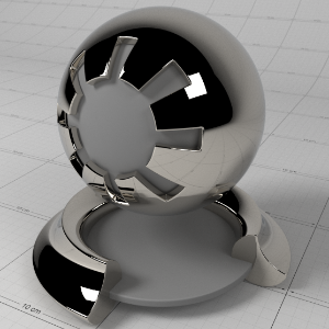
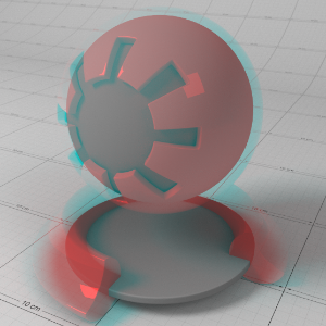
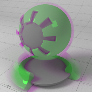
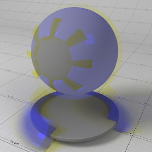
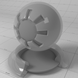
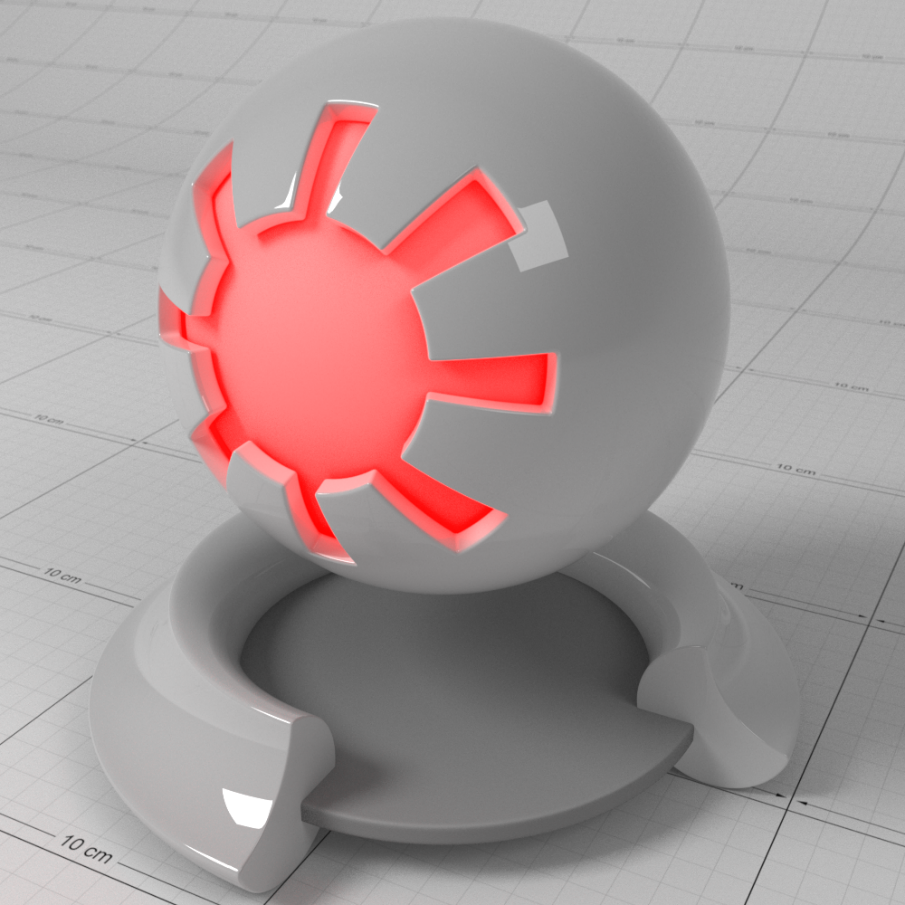
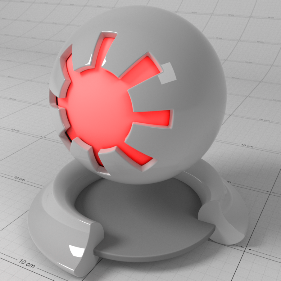
Energy Conservation Mode
Energy conservation is an important feature of the Redshift Material, as it ensures physically plausible lighting for more realistic results. A material can be considered as a stack of layers, where light energy is transmitted from layer to layer, with each layer losing a certain amount of energy. For example, the amount of energy not reflected by the top-most layer (due to Fresnel) can then be refracted or diffuse. This mode lets you choose how the energy is transmitted between layers;
- "Mono" uses the luminance of the remaining energy to affect layers below. This is the mode used by other Redshift material shaders, such as Architectural.
- "RGB" uses the remaining color energy to affect the layers below. For example, if a reflection layer is pure red (1.0, 0.0, 0.0), then the energy remaining for diffuse or refraction will be (0.0, 1.0, 1.0).
Energy Conservation in Detail
Conceptually, the material can be visualized as layers like so:
- Coating
- Reflection
- Refraction / Diffuse / Sub-surface Transmission and Scattering
For physical correctness, energy is automatically conserved between these conceptual layers and between the diffuse/refraction/sub-surface layer so that the amount of light reflected is no more than received. In other words, a highly reflective material will have very little diffuse lighting or refraction/transmission.
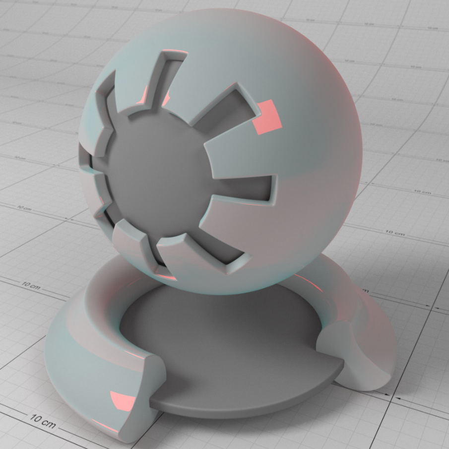
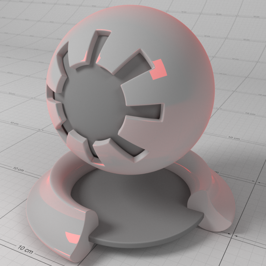
Below shows a comparison between energy conservation modes with a tinted base reflection and grey base diffuse color. Notice how under "RGB" mode, the diffuse color takes on some of the inverse color of the red reflection tint – this is correct, because the diffuse layer gets the remaining energy that was not reflected. Notice how under "Mono" mode the diffuse color remains grey:
|
|
|
|
Conservation Mode: RGB
|
Mono |
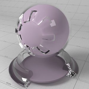
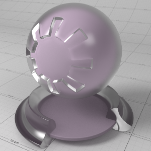
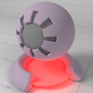
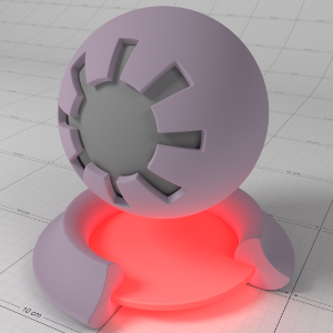
'Overall Tint' Affects Emission
Enabling this option forces the 'Overall Tint' to also affect the material emission color. When using the 'Overall Tint' to affect lighting (such as using ambient occlusion shader results), you should leave this option un-checked for more realistic results.
Enabling the 'Overall Tint Affects Emission' option allows you to apply the ' Overall Tint' to the emissive part of the material. If the 'Overall Tint' is meant to just affect lighting, this option should be un-checked.
Below shows a comparison between this option being enabled and disabled, with AO driving the 'Overall Tint' of the emissive ball material. With the option enabled you can see the AO shadow affects the emissive strength of the ball material:
|
|
|
|
'Overall Tint' Affects Emission: disabled |
Enabled |
Reflection End Color
This setting is used whenever the Trace Depth for reflections is exceeded. The color set here is then used to calculate the last reflection.
- Environment: The color is taken from an available environment or will be black, if there is no environment.
- Diffuse: The color ist taken from the diffuse (Base) color of the material
Anisotropy
Surface Orientation
When this option is set to 'None', Redshift will attempt to compute an axis automatically based on the surface normal. This can be acceptable for simple flat surfaces, but can produce unpredictable results for other types of surfaces.
UV Set
This option allows you to specify a named UV Set or Tangent Set to define the surface axis that is used to control anisotropic reflection direction.
UV Channel
The vertex attribute channel name for UVs to drive the surface orientation for anisotropic reflections.
Tangent Channel
The vertex attribute channel name for Tangents to drive the surface orientation for anisotropic reflections.