OpenPBR Material
Overview
The OpenPBR material is a physically based über-shader that presents as a standardized combination of the Autodesk Standard Surface and the Adobe Standard Material models. It is hosted by the Academy Software Foundation (ASWF) and organized as a subproject of MaterialX.
More information about the history and design can be found on this page detailing the OpenPBR Surface specification.
The OpenPBR material is made up of several layers.
-
Base: The base layer sits at the bottom and can be configured to simulate many material types. It can represent a dielectric or metallic material and is responsible for the primary reflection layer. This is controlled by the Metalness parameter found in the Base parameters group. Normally materials are either fully metallic (Metalness 1) or fully dielectric (Metalness 0) but the OpenPBR material also supports a mixture when Metalness values fall between 0 and 1.
-
Metallic: When Metalness is used, reflections take on the Base Color and the Specular Color controls the color seen at glancing angles. Primary parameter groups are Base and Specular.
-
Dielectric: When a material is non-metallic it can be set up to represent the three main conditions covered below, but blending between them is possible by adjusting their relevant weights.
-
Glossy-diffuse: An opaque dielectric material that's good for many common materials that don't exhibit significant light scattering or transmission like wood and stone. Primary parameter groups are Base and Specular.
-
Subsurface: An opaque dielectric material that heavily scatters light internally like skin, plastic, marble, and wax. Primary parameter groups are Base, Specular, and Subsurface.
-
Translucent: A dielectric material that transmits and refracts a significant amount of light and one that is more transparent than a subsurface material. Primary parameter groups are Base, Specular, and Transmission.
-
-
-
Thin-Film: A very thin dielectric layer, measured in micrometers, between the base and coat layer used to represent the colorful effects as seen with soap bubbles, insects, and oil mixing with water.
-
Emission: A light emitting layer that sits above the base layer but below the coat and fuzz layers. The emissive layer is tinted by the coat and fuzz, making it easy to represent emissive surfaces like a TV screen — using the coat for the reflective glass and the fuzz for dust on top.
-
Coat: An optional dielectric layer that adds a secondary reflection layer over the base layer, great for clear coats and varnish.
-
Fuzz: An optional layer that sits on top of everything that can be used to simulate dust or the velvety sheen of cloth.
In practice, working with the OpenPBR material has many similarities to Redshift's Standard material, including the set up of special effects like thin-walled diffuse transmission as seen in materials like paper and leaves. The most readily apparent differences may be seen when using the Coat Darkening effect (enabled by default) and the behavioral differences in OpenPBR's Fuzz layer vs the Standard Material's Sheen.
Parameters
|
Base
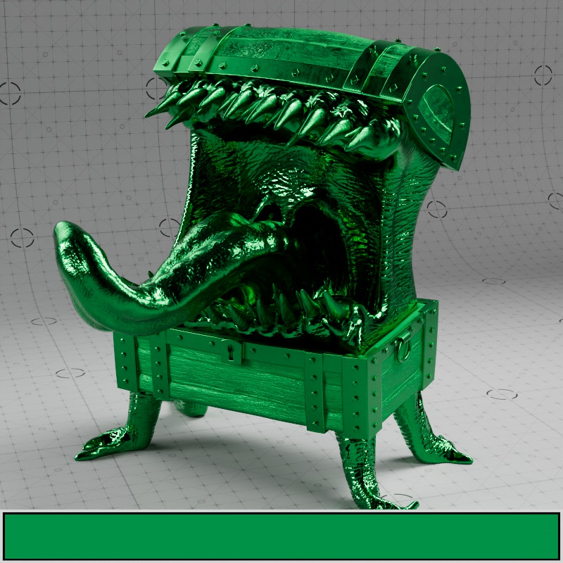
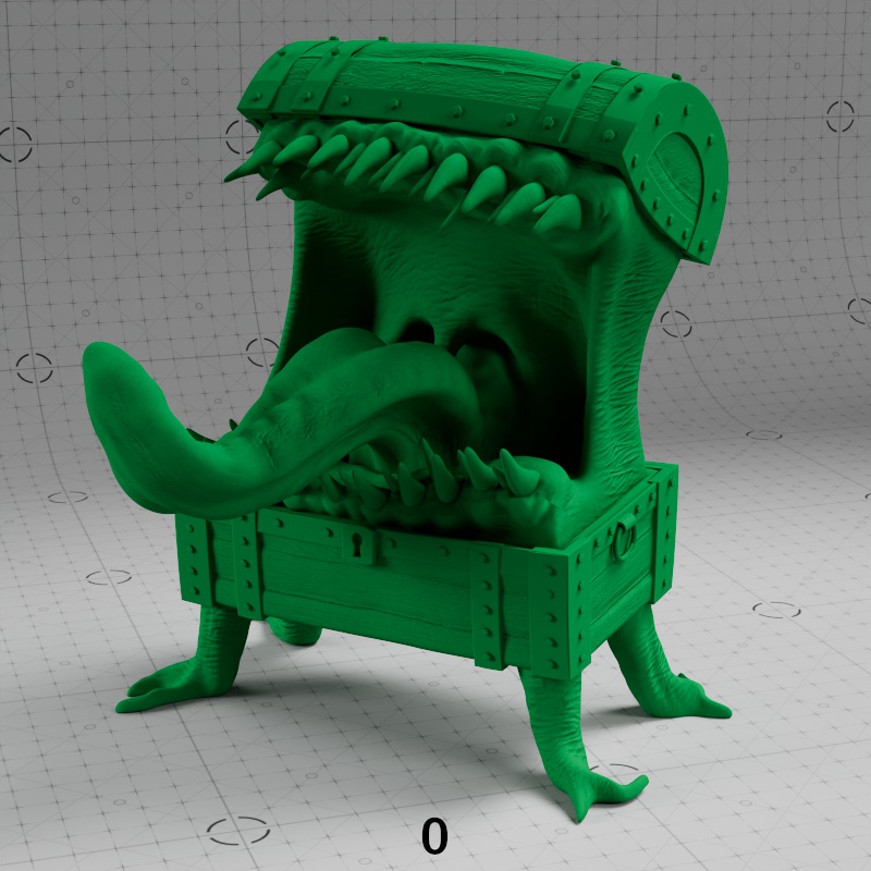
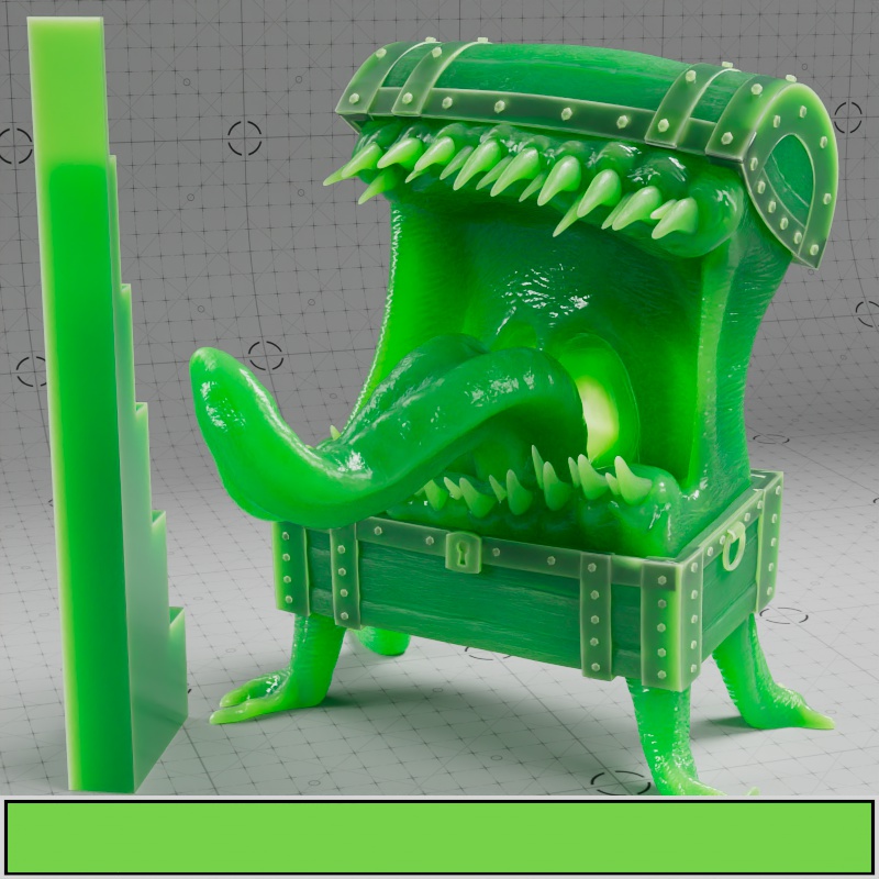
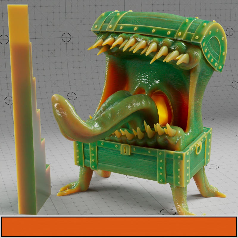
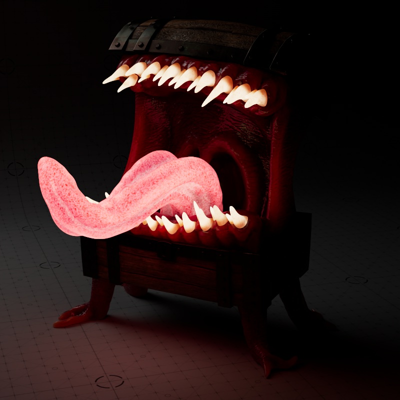
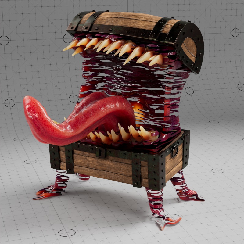
Weight
Controls the intensity of diffuse or metallic reflections when multiplied by the Base Color. A value of 1 represents full intensity, while 0 reflects no light.
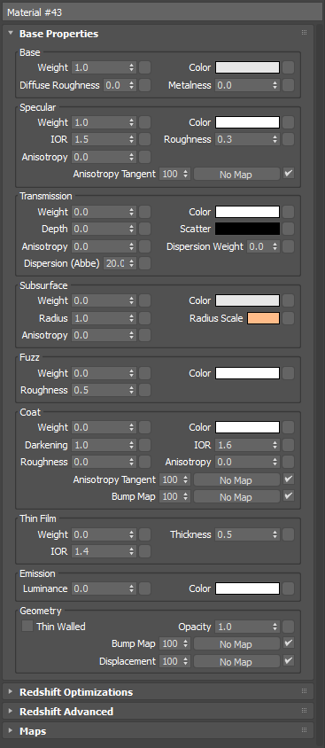
Mimic model by Ian Robinson
Note, in the examples below the mouth and body are unaffected because they have a subsurface scattering weight of 1.
|

|

|
| Base Weight: 1.0 | 0.5 | 0.0 |
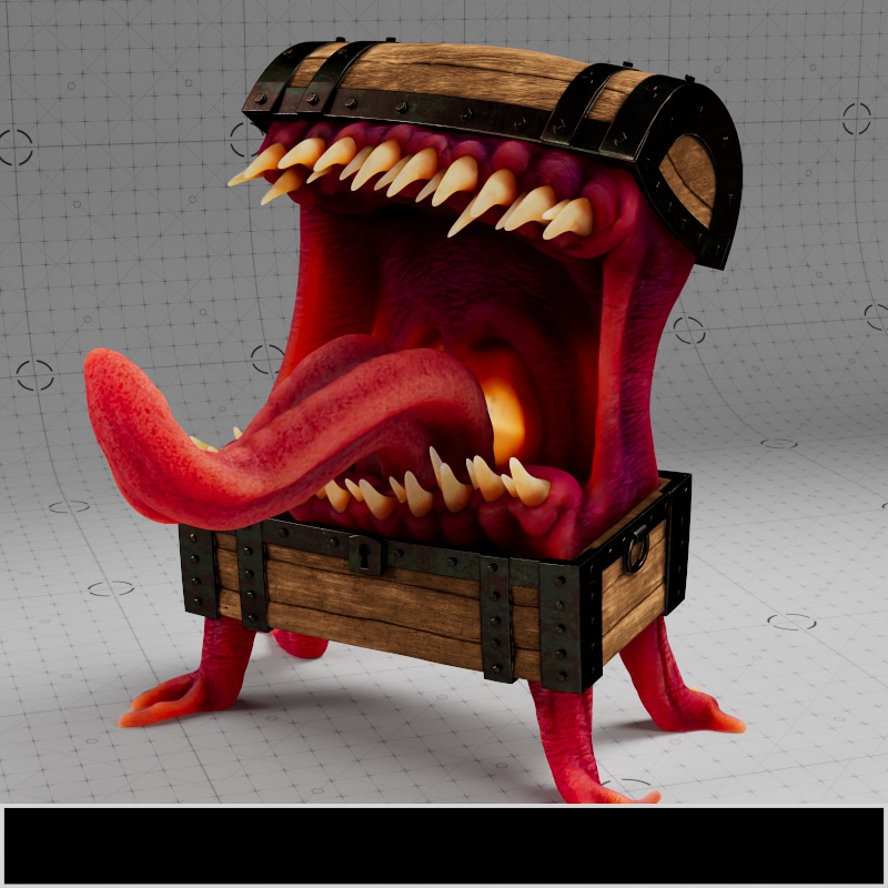
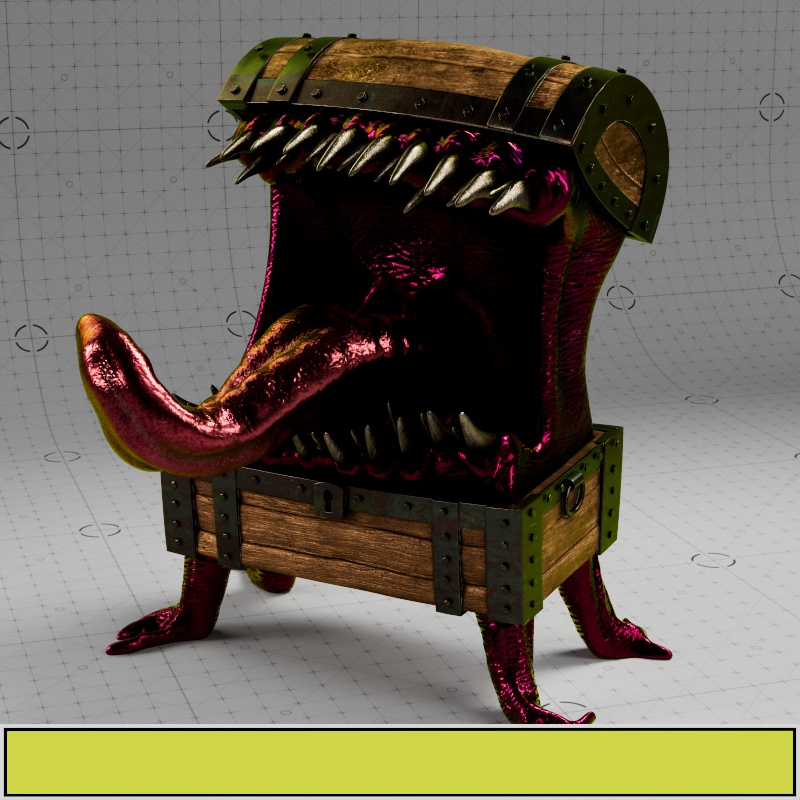
Color
Defines the primary color of the surface for diffuse and metallic reflections. The intensity of the color is the product of multiplying by the Base Weight.
When Metalness is greater than 0 the Base Color determines the color of metallic reflections at facing angles as seen in the examples below.

|

|
|
|
| Base Color: Textured Metalness: 0 |
Green | Purple | Black |

|
|

|

|
| Base Color: Textured Metalness: 1 |
Green | Purple | Black |
Diffuse Roughness
Controls the micro-surface roughness of diffuse reflections using an energy preserving Oren-Nayar (EON) reflection model. This is useful for simulating matte or dirty surfaces. Higher values represent rough surfaces like rock and sand, scattering light in more random directions. Lower values represent smooth surfaces that reflect light more evenly resulting in greater surface definition. A roughness of 0 scatters light equally in all directions using Lambertian reflection.
|

|
| Base Roughness: 0 | 1 |
Metalness
Controls if the material behaves as a non-metal (dielectric) or metallic material. A value of 0 represents a non-metal material that can exhibit diffuse reflections, subsurface scattering, or transmission. A value of 1 represents a fully opaque metallic material — blocking any subsurface scattering or transmission and replacing diffuse reflections with metallic reflections. Values between 0 and 1 blend between the two behaviors.
When Metalness is used:
- The Base Color controls the color of reflections at facing angles.
- The Specular Color controls the edge tint color of reflections, at grazing angles along the edges of a surface.
- The Specular Weight controls the reflection intensity of the metal.
In the example below the entire object animates from no metalness to full metalness. Note how subsurface scattering gradually disappears as it approaches full metalness and the reflection colors are tinted by the textures.
| Metalness: 0 |
Specular
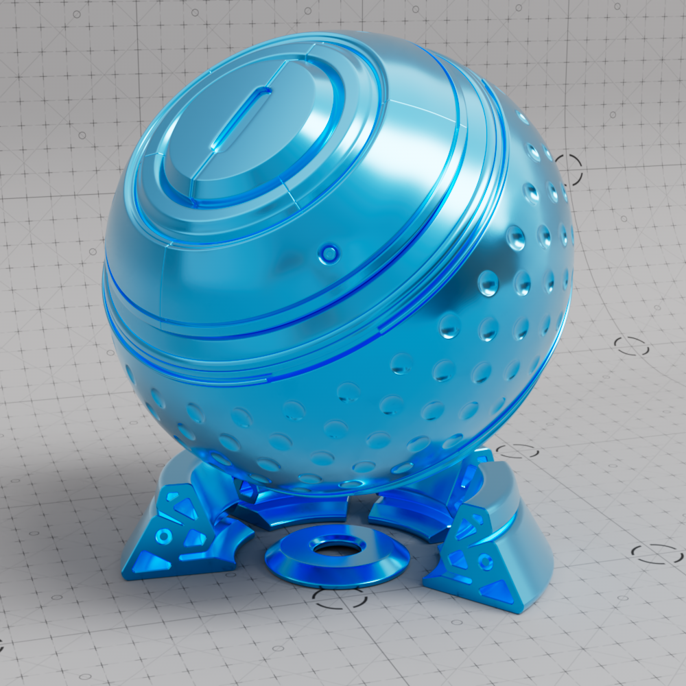
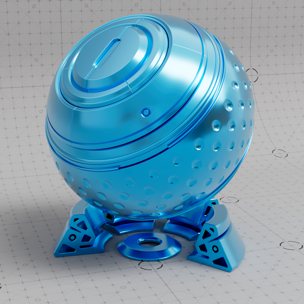
Weight
Controls the intensity of specular reflections by multiplying with the Specular Color. Higher values exhibit strong reflections while lower values exhibit weaker reflections.

|

|

|
| Specular Weight: 1.0 (default) | 0.5 | 0.0 |
Color
Controls the overall specular reflection color for non-metals and the reflection color at grazing angles for metallic materials. For physically accurate non-metals this should be left at the default white.
In the examples below note the difference in behavior when metalness is used, on non-metallic surfaces all reflections take on the specular color while metallic surfaces only tint reflections along the edges as the surface reaches a grazing angle to the viewpoint. Additionally, a black specular color completely disables reflections on non-metals while only dimming the edges on a metallic surface.
|
|
|
| Specular Color: White (default) Metalness: 0 Base Color: Textured |
Yellow | Black |

|
|

|
| Specular Color: White (default) Metalness: 1 Base Color: Grey |
Yellow | Black |
IOR
IOR, short for Index Of Refraction, controls how light is reflected off of non-metals as well as how light is bent in transmissive materials. IOR is a physical based value so you can look up the IOR for a specific material online for accurate results, but most dielectric materials have an IOR between 1.4-1.6. Higher values result in more intense reflections while lower values result in weaker reflections.
IOR defines how fast light rays move through a medium, when a light ray passes between mediums with a different IOR the ray bends because of the difference in the speed of light for each medium. A light ray moves through air at the speed of light but slows down when it passes into glass or water causing it to bend and distort. A value of 1 represents how light behaves in a vacuum, light rays are not bent since a vacuum does not interact with the rays at all. Most materials never have an IOR below 1 since it would mean light travels faster in this medium than it does in a vacuum.
IOR has no effect on metallic materials, note how the dark metal in the example sees no change.
| Specular IOR: 1-3 |
Roughness
Controls how smooth or rough of the specular reflection. Higher values scatter light in more random directions resulting in blurry reflections, a value of 1.0 results in an almost diffuse appearance. Lower values concentrate the light into sharper and more distinct reflections, a value of 0 results in a perfectly polished surface.
Roughness simulates microfacet surface imperfections by controlling how light bounces off the surface. As roughness increases reflected light scatters all over the scene, simulating a bumpy uneven surface, so less of it bounces back into the camera which results in a visually dimmer overall reflection. As roughness decreases the reflected light is scattered less, simulating a very smooth surface, with more of it bouncing back directly into the render camera resulting in brighter and sharper reflections. This is why wet materials tend to look shiny, liquids — which tend not to exhibit any surface roughness — fill in the gaps of an otherwise porous surface creating the appearance of a smooth surface and brighter reflections. However it's important to note, the amount of light reflected back is always the same thanks to conservation of energy, regardless of the roughness value.
| Specular Roughness: 0 -1 |
Anisotropy
Requires a Specular Roughness greater than 0.
Controls how far coat reflections stretch in a particular direction. Anisotropy is used to represent materials like brushed metal that have elongated specular reflections due to their fine grooves rather than round reflections that would occur with a smooth surface. Low values represent isotropic reflections with less stretching while higher values result in more stretching with high directionality.
| Specular Anisotropy: 0 -1 Specular Roughness: 0.4 |
Anisotropy Tangent
Connect a Surface Tangent node here to control the anisotropic reflection direction.
For more information please see the Surface Tangent page.
| Changing rotation with the Surface Tangent |
Transmission
Weight
Controls the amount of light that can pass through the surface. Useful for transparent materials like glass, liquids, and plastics. When used with scattering, transmission can also represent thicker materials like milk, orange juice, honey, and other materials that are have heavy light scattering properties but are still transparent.
A Transmission Weight of 1 overrides all base layer shading attributes except Metalness. So if you want to mix subsurface scattering with transmissive properties make sure to use a Transmission Weight lower than 1.
| Transmission Weight: 0 - 1 Transmission Color: Light Brown |
Color
Controls the transmission color.
Refraction color is heavily dependent on the Transmission Depth parameter, the examples below compare the difference between a Depth of 3 units versus 0. For reference, the Mimic's body is about 5 units thick.
Note how the objects exhibit a stronger refraction color in thick areas when Depth is set to 3, compared to the constant coloration exhibited when Depth is 0. For more detail on this behavior, please see the Transmission Depth parameter description.
|
|
|
||
| Transmission Color: Light Green Transmission Weight: 1 Depth: 3 |
Light Brown | Animated Color Value | Animated Color Saturation |
|
|
|
||
| Transmission Color: Light Green Transmission Weight: 1 Depth: 0 |
Light Brown | Animated Color Value | Color Saturation |
Depth (cm)
Fixed Unit: Centimeters
Controls the distance in centimeters a ray needs to travel before the transmission color reaches full saturation. As light travels through a medium light is attenuated, this means that thicker areas of an object are darker and more saturated than thinner areas. At high depth values, the visual density of the object decreases resulting in less absorption of color in the object. Therefore, Transmission Depth should be set in accordance with the actual thickness of the object for realistic results.
For example, with a transmission color of red, when the depth is low the transmission color is reached early resulting in a rich red color that makes the object look dense — if the object is thick enough for the ray to travel farther than the depth value the transmission color becomes an even darker shade of red until it starts to look black and opaque. On the other hand, if transmission depth is high it takes longer for the ray to reach full saturation, resulting in a desaturated look in the thinnest parts of an object that make it look more like clear glass. When a depth value of 0 is used the transmission is fully tinted with the Transmission Color at all depths.
At a transmission depth of 0 no scattering takes place and transmission looks the same regardless of the scatter color or the thickness of the object. When the depth is low the object looks dark and dense with a more pronounced scattering effects, however at higher depth values the scattering effect becomes less pronounced and the object starts to look more like clear glass.
| Transmission Depth: 0 - 10 Transmission Scatter Color: Orange Transmission Color: Light Brown |
Scatter Color
A Transmission Depth value greater than 0 is required for transmission scattering.
Controls the subsurface single scattering component that simulates microscopic particulate suspended in a medium, this is similar to multiple scattering but better suited to thinner volumes. Transmission scattering is useful for subsurface scattering in plastics, thick fluids like orange juice or milk, and large volumes of thin fluids like the ocean to reproduce its typical blue tint.
Light colors result in more scattering while dark colors result in less scattering, by default the black scatter color results in no scattering. For more information on controlling the scattering look see the Transmission Depth parameter above.
|
|
|
||
| Scatter Color: Purple -Animated color value Transmission Depth: 1 Transmission Color: White |
Purple - Animated color saturation | White | Black |
Scatter Anisotropy
Requires a Transmission Depth greater than 0 and a Transmission Color other than Black.
Controls the direction transmissive light is scattered.
The default anisotropy of 0 results in isotropic scattering, when the light scatters equally in all directions. Positive values increase the chance for forward scattering, when more light is scattered in the direction the light rays are traveling. Negative values increase the chance for back scattering, when more light is scattered back at the light source.
In the examples below, note how the final result is highly dependent on the location of the light source relative to the transmissive object. All examples showcase a transmission anisotropy from -0.8 to +0.8, positive values frequently lead to a more glassy appearance while negative values lead to a more frosted look.
| Transmission Scatter Anisotropy: -0.8 to +0.8 Front Lighting |
-0.8 to +0.8 Standard Lighting |
-0.8 to +0.8 Back Lighting |
Dispersion Weight
Controls the intensity of Transmission Dispersion with a linear multiplier from 0 to 1. Higher values result in more dispersion while a value of 0 represents no dispersion.
| Dispersion Weight: 0 - 1 |
Dispersion (Abbe)
Controls how much the refractive index (IOR) in a transparent material varies across light spectrum wavelengths, this variance results in a color shift in the material. Low values represent intense dispersion while high values result in little to no dispersion. Note, dispersion behaves similarly to a roughness effect so it can add additional noise that takes more samples and time to clean up.
Common values range from around 10 for glass and 70 for diamond, in general higher quality materials exhibit lower amounts of dispersion. A value of 0 represents no dispersion.
| Dispersion: 0 - 5 |
Subsurface
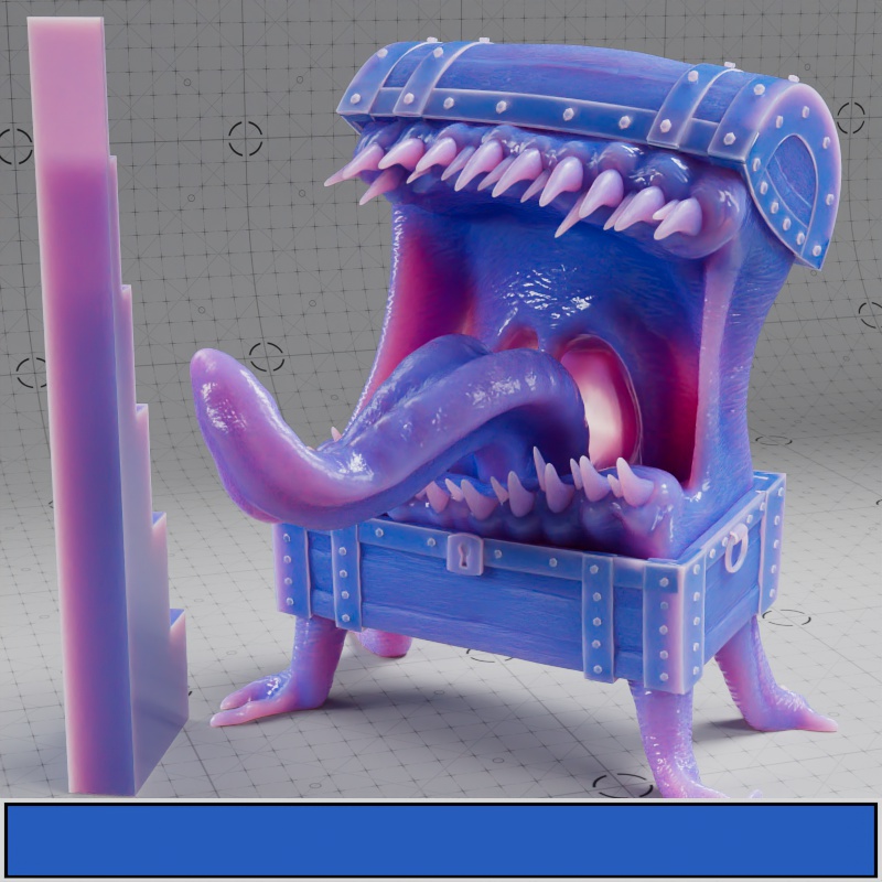
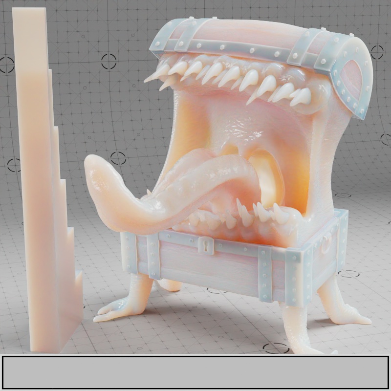
Weight
Controls how much subsurface scattering is used versus diffuse shading. High values represent heavy subsurface scattering while low values result in less scattering. A Subsurface Weight of 1 only uses subsurface scattering — blocking any base diffuse shading.
In the examples using the full texture setup, only the Mimic's body, teeth, and tongue have subsurface scattering. Additionally, where metalness is used, no subsurface scattering can appear.
| Subsurface Weight: 0 - 1 |
Color
Controls the primary surface color of the subsurface scattering effect. Light scatters inside an object, is transported back to the surface, and takes on this overall color. In a material for skin, a skin tone is appropriate for the subsurface color.
The Subsurface Color may be thought of as the albedo color for the subsurface effect, as low scatter values result in a very diffuse look. Comparatively, the deeper scatter effects primarily comes from the Subsurface Radius depth and Radius Scale color, in the examples below a bright orange is used for the Radius Scale Color that becomes prominent in the thinnest parts of the models. Where black is used no subsurface scattering takes place at all.

|
|
|

|
| Subsurface Color: Textured Subsurface Radius Scale: Orange (1, 0.5, 0.25) Subsurface Weight: 1 |
Blue | White | Black |
Radius
Controls the average distance in scene units light rays can travel before being scattered or absorbed, in physics this is known as the mean free path. For example, if your scene uses centimeters then a radius value of 10 results in subsurface scattering traveling up to 10 centimeters.
High values represent light scattering a great distance which results in a soft and more waxy look, while low values represent light scattering a short distance resulting in a dense and more diffuse look. High and low values are relative to your scene scale and your object's size.
The total distance light can travel in a subsurface object is obtained by multiplying the Radius Scale's RGB values by the Radius. Because of this, each color channel has the opportunity to travel a different amount.
For example, given a Radius Scale of (1, 0.5, 0.3) and a Radius of 10 , the red channel can travel the full 10 units, the green channel can travel 5 units, and the blue channel can only travel 3 units.
| Subsurface Radius: 0 - 10 Subsurface Color: Textured Subsurface Radius Scale: Orange (1, 0.5, 0.25) |
Radius Scale
Subsurface Radius Scale controls the average distance the red, green, and blue wavelengths travel before returning to the surface. Colors that are able to travel deeper before returning to the surface have a stronger presence in the final result.
Light colors (high values) result in more scattering and dark colors (low values) result in less scattering. A Radius Scale color of white means all colors are scattered equidistant and a black color results in no subsurface scattering.
For example, a radius scale color with RGB values (1, 0, 0) would mean that only the red wavelength travels beneath the surface, while the green and blue components are completely stopped from scattering. This is similar to human skin, where red scatters deeper than green and blue. The radius scale can be a powerful parameter to tweak for varied looks with different color shifts.

|
|
|
||
| Subsurface Radius Scale: White (default) Subsurface Color: Green Subsurface Radius: 0.75 |
Green |
Orange |
Orange - Animated color value |
Orange - Animated color saturation |
Anisotropy
Only relevant for Random Walk mode. Values close to the extreme ends (-1 and 1) may result in an unwanted look as the light scattering becomes so highly concentrated in a single direction.
Controls the direction light scatters inside a subsurface object within a -1 to 1 range. Adjusting a material's anisotropy allows for artistic control and increased realism.
The default anisotropy of 0 results in isotropic scattering, when light scatters equally in all directions. Positive values increase the chance for forward scattering, when more light is scattered in the direction the light rays are traveling. Negative values increase the chance for back scattering, when more light is scattered back toward the light source.
In the examples below, note how the final result is highly dependent on the location of the light source relative to the subsurface object. All examples showcase a subsurface anisotropy from -0.9 to +0.9, positive values frequently lead to a more glassy appearance while negative values lead to a more frosted look.
| Subsurface Anisotropy: -0.9 to +0.9 Front Lighting |
-0.9 to +0.9 Standard Lighting |
-0.9 to +0.9 Back Lighting |
Fuzz
Weight
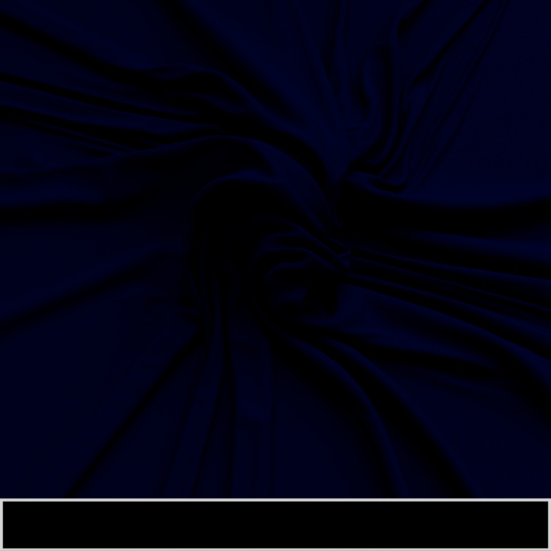
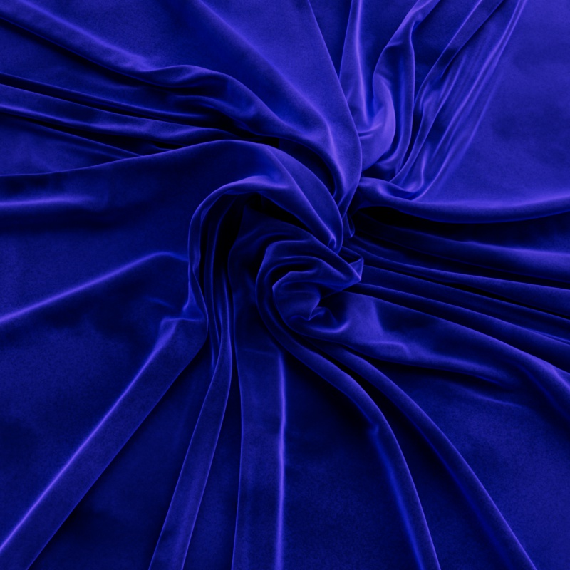
Controls the coverage and density of a scattering layer that simulates a fuzzy cloth or dusty layer on top of all other shading layers. When 0.0 the fuzz effect is disabled.
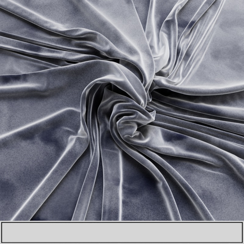
Cloth model by Fuchs & Vogel
| Fuzz Weight: 0 - 1 Fuzz Color: |
Color
Controls the color of the fuzz effect.
|
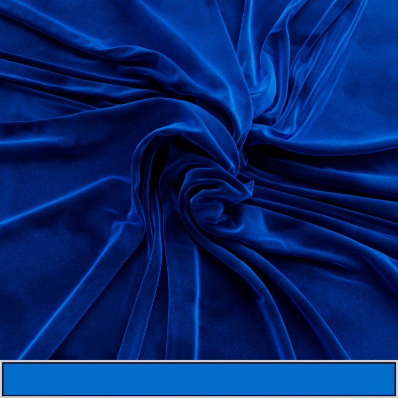
|

|
|
| Fuzz Color: White | Blue | Texture | Black |
Roughness
Controls the look of the fuzz by changing the shape of the simulated multi-scatter fuzz microflakes. At high roughness the microflakes take on a spherical shape resulting in a soft look with more isotropic scattering, while low values represent microflakes that are more elongated and fiber-like that tend to have the greatest impact at grazing angles.
|
|
| Fuzz Roughness: 0 - 1 | Textured |
Coat
Weight
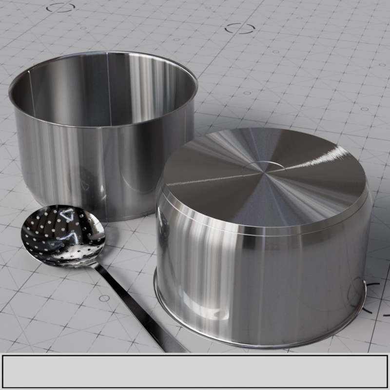
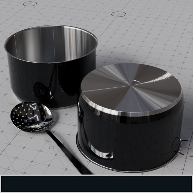
Controls the intensity of a transparent reflective coat layer that sits just below the fuzz layer but above all others. This is good for simulating a clear coat or varnish. Coat is disabled at 0.0 while higher values increase the intensity of the coat.
The pot example adds a blue coat around the outside while the Mimic receives a white coating across its entire surface, giving it a sort of slimy appearance.
| Coat Weight: 0 - 1 | 0 - 1 |
Color
Controls the coats transparency color which tints the layers beneath. Note, this doesn't affect coat reflection colors (they remain white) but it does tint the specular reflection and base layers beneath the coating.
In the examples below, note how the anisotropic reflections beneath are tinted by the Coat Color but the glossy reflection of the spoon in the coat is not tinted. A coat color of black disables the coat completely but very dark colors can be used to represent a dense coat as seen in the Dark Blue example below.
|

|

|
|
| Coat Color: White (default) | Blue | Red | Dark Blue |
Darkening
It's common for a coat layer to saturate colors and darken the surface beneath due to numerous internal reflections that take place in the coat. Darkening controls how intensely the coat layer is able to darken the layers beneath. High values represent heavy saturation and darkening while low values reduce the effect. By default darkening is used at the heaviest level (1) but a value of 0 disables it completely.
High IOR values also increase the number of bounces which leads to even heavier darkening.
| Coat Darkening: 0 - 1 | 0 - 1 |
IOR
Sets the index of refraction (IOR) used to calculate the strength of the coating. An IOR of 1.0 disables the coat.
| Coat IOR : 1 - 3 |
Roughness
Controls the roughness of the coat. A roughness value of 0.0 represents a perfectly polished smooth surface while a roughness value of 1.0 represents an almost diffuse appearance.
Note, when the coat is rough both coat reflections and specular reflections on the base layer are affected. This is because the light is scattered as it passes through the coat layer before it can reach the base specular reflection layer. In the metal pot example, note how the anisotropic reflections change as the coat roughness increases.
| Coat Roughness: 0 - 1 | 0 - 1 |
Anisotropy
Requires a Coat Roughness greater than 0.
Controls how far coat reflections stretch in a particular direction. Anisotropy is used to represent materials like brushed metal that have elongated specular reflections due to their fine grooves rather than round reflections that occur with a smooth surface. Low values represent isotropic reflections with less stretching while high values result in more stretching with high directionality.
| Coat Anisotropy: 0 - 1 Coat Roughness: 0.5 |
Anisotropy Tangent
Connect a Surface Tangent node here to control the anisotropic coat reflection direction.
For more information please see the Surface Tangent page.
Bump Map
Connect a bump map node to this input that will only affect the coat layer. Coat bump mapping is separate from the base layer, this means you can apply details like scratches on the coating without affecting the base layer. Alternatively, by only plugging a bump map into the base 'Geometry' Bump input of the material and leaving the 'Coat' Bump input empty you can easily achieve a clear coat or varnish effect.
In the example below, note how the anisotropic reflections beneath the blue coat remain unaffected by the coat bump map.

|

|
| Coat Bump: Disabled | Enabled |
Thin Film
Weight
Controls the intensity of the iridescent thin film effect.
| Coat Weight: 0 -1 |
Thickness (µm)
Fixed Unit: micrometers
Controls the thickness of the thin film in micrometers, the thickness influences the color shifting effects by controlling the spacing of the colored bands. This effect looks particularly interesting when thickness is varied slightly, for example, remapping a noise texture into an appropriate thickness range.
When light hits a thin film some light reflects off the top of the film while some passes through and reflects off the bottom of the film. When this happens the light interferes with itself, becoming darker or brighter depend on several factors like the thickness of the film and the color of the light. In physics this is called wave interference, when the light waves constructively interfere with each other they get brighter, but when they destructively interfere they get darker. Practically speaking, the thin film effect is great for colorful iridescent effects as seen on soap bubbles.
Most thin film effects take place between 0 and 1 micrometers. When the layer becomes too thick (around 3 micrometers) the effect will even disappear — this is physically accurate.

|
|
| Thickness: 0 - 1 |
Textured |
IOR
Controls the refractive index of the thing film which affects the thin film's color.
| Thin Film IOR: 1 to 3 |
Emission
Luminance (cd/m^2)
Controls the intensity of the emitted light in nits when the emission color is white. Higher values result in brighter colors and stronger global illumination.
Note, emission intensity is affected by the layers that sit above it — coat and fuzz. For example, coat can dim emission intensity but if emission is bright enough this may not be apparent.
| Emission Luminance: 0 to 5000 |
Color
Controls the color of the emission. Emission casts light in the scene by using indirect global illumination rays to cast diffuse lighting on other objects in the scene.

|

|
|

|
| Emission Color: White Emission Luminance: 5000 |
Blue | Textured | Textured |
Geometry
Thin Walled
This option is useful for thin refractive materials such as a pane of glass, where the ray-bending effect is not noticeable and modeling actual object thickness is not worth it. When this option is enabled, refraction rays enter and immediately exit the medium without bending.
When Thin Walled is enabled the behavior of the OpenPBR material changes in the following key ways:
-
The Subsurface parameters are used to control a diffuse transmission appearance that works well for thin materials like paper and leaves.
-
Dispersion effects are disabled.
Enabling this option preserves the reflection fresnel effect while internally disabling any medium interface transitions that would allow rays to bend.
In the examples below you can see a noticeable difference when this option is enabled. When enabled by default, refractions bend and distort realistically.
|
|
|
| Thin Walled: disabled Transmissive |
Thin Walled: enabled Transmissive |
Opacity
Controls where a material is present, with higher values making an object appear more opaque. If using a texture, white represents a fully opaque material while black represents a completely invisible material that is effectively cut out — grey values in between blend between the two.
This effect is entirely dependent on the Transparency trace depth found in the Render Settings Globals section. If you only need cutout transparency, with no grey-scale values, you should instead make use of the drastically more efficient Redshift Sprite shader.
|
|
| Opacity: 0 - 1 | Textured |
Bump Map
Connect a bump map here to add detail to the material's surface and affect all shading layers except the coat layer.

|

|
| Bump Map: Disabled |
Enabled |
Redshift Optimizations
Enable Trace Depth Overrides
Enables the per-material Reflection and Transmission Trace Depth parameters below. When disabled, global trace depths are used.
Reflection
Trace Depth
Controls the number of times a reflection ray can bounce off this material, like with reflections in reflection.
If the reflections on a material are not very defined (for example: they are blurry because of high roughness or have a low specular weight), then multiple bounces can be a waste of rendering time. This parameter allows the user to reduce the trace depth and speed up rendering.
Override Cut-Off
Enables a per-material override of the global cut-off settings for reflections.
Cut-off Threshold
When the reflections of a material are very dark they contribute very little to the final image. This parameter defines what is considered "very dark," at which point no more reflection rays are shot - speeding up the render. Scenes that contain very strong lights might need this parameter set to very low values such as 0.0001 in order to avoid early termination of tracing which can produce a grain-like effect.
Refraction
Trace Depth
Controls the number of times a transmission ray can bounce through this material. If the refraction rays of a material are not very defined (meaning: they are blurry because of high roughness or have a low weight), then multiple bounces can be a waste of render time. This parameter allows the user to reduce the trace depth and speed up rendering.
Override Cut-Off
Enables a per-material override of the global cut-off setting for transmissive refractions.
Cut-off Threshold
When the refractions of a material are very dark they may contribute very little to the final image. This parameter defines what is considered "very dark," at which point no more refraction rays are shot - speeding up the render. Scenes containing very strong lights might need this parameter set to very low values such as 0.0001 in order to avoid early termination of tracing which can produce a grain-like effect.
Combined Trace Depth
Controls the combined trace depth of your material.
"Use Combined Trace Depth from Materials" must be enabled in the 'Render Settings' System > Legacy.
Redshift Advanced
The advanced options allow you to tune powerful features of the material that may not be frequently used and may break realism and energy conservation.
Diffuse
Direct Scale
Scales the weight of direct diffuse lighting rays — rays that intersect lights in the scene. Setting this value to 0.0 disables direct lighting for the diffuse component.
For physically correct results both the 'Direct' and 'Indirect' lighting scales should be 1.0 (or the same value).
In the example below, note how the primary diffuse lighting reacts to the direct scale, but the green bounce lighting from the environment is only affected by the indirect scale.
 Diffuse Direct Scale: 0 -1 Diffuse Direct Scale: 0 -1 Diffuse Indirect Scale: 0 -1 Diffuse Indirect Scale: 0 -1 |
Indirect Scale
Scales the weight of indirect diffuse lighting rays — rays that intersect surfaces in the scene. Setting this value to 0.0 disables indirect lighting (global illumination) for the diffuse component, which may be a useful optimization when indirect lighting is already extremely subtle.
Reflection
Direct Scale
Scales the weight of direct reflection rays — rays that intersect lights in the scene. Setting this value to 0.0 disables the direct reflection of lights.
Note for physically correct results both the 'Direct' and 'Indirect' lighting scales should be 1.0 (or the same value).
In the example below, note how the reflections of the lights react to the direct scale, but the green reflection of the environment is only affected by the indirect scale.
|
Reflection Direct Scale: 0 -1 Reflection Indirect Scale: 0 -1 |
Indirect Scale
Scales the weight of indirect reflection rays — rays that intersect surfaces in the scene. Setting this value to 0.0 disables reflections of other objects.
End Color
Controls what is reflected when the Reflection Trace Depth is exceeded.
- Environment: The final reflection is taken from an available environment shader (like a dome light) or will be black if there is no environment.
- Diffuse: The final reflection color is taken from the Base Color of the material.
When trace depths are low, or an object's shape creates many self reflections, this parameter can have an enormous difference on the final look. For example, the metallic shader ball in the examples below appears to glow in tight spaces when the reflection trace depth is low and End Color is set to "Environment." This is because the dome light environment is a bright sky reflection, so once the final trace depth is reached these confined areas reflect the bright sky even though they are primarily occluded by geometry.
Increasing the reflection trace depths can fix this issue, resulting in more realistic dark reflections, but this comes at the expense of render time - alternatively the End Color can simply be set to "Diffuse." Sometimes this is enough to produce a very similar result to increasing the trace depths but avoids the render time increase.
|

|
| End Color: Environment Reflection Trace Depth: 4 |
Environment 32 |
|
|
| End Color: Diffuse Reflection Trace Depth: 4 |
Diffuse 32 |
Samples
Controls the number of Specular reflection samples. Using more samples reduces noise but takes longer to render, while using fewer samples is faster but may introduce undesirable noise.
Blurry reflections (when "Specular Roughness" is greater than 0.0) need more samples to achieve a clean "noise-free" result.
Transmission
Direct Scale
Scales the weight of direct Transmission rays — rays that intersect lights in the scene. Setting this value to 0.0 stops lights from being directly visible in transmissive objects.
In the example below, note how the direct refraction of the light is controlled with the direct scale. This also affects the caustics from the light cast on the ground.
| Transmission Direct Scale: 0 - 1 |
Fresnel Affects Shadow
Thin Walled must be disabled.
Controls whether reflectance is taken into account when calculating a transmissive object's shadow from the following options:
-
On: Fresnel reflectance is taken into account, resulting in more physically accurate shadow rendering and sometimes a look that resembles caustic rendering. For most circumstances this results in more realistic renders in a fraction of the time compared to rendering with caustics. Even completely clear materials like glass cast a shadow, and under certain circumstances they can be quite dark, this is because light reflected off the object may be more concentrated in some directions than others.
-
On (no internal reflection) - Default: Fresnel reflectance is taken into account but internal reflections are ignored resulting in a weaker shadow overall. This setting results in more realistic shadows than the "Off" setting without shadows that may be too dark for a thick pieces of glass.
-
Off: Fresnel reflectance is not taken into account and the shadow of a transmissive object is controlled entirely by the Shadow Opacity parameter.
Please keep in mind that the softness of the shadow is entirely dependent on the lights in the scene.
In the example images below note how the shadows of the objects are brighter in the center than their edges because the fresnel reflections from the surface scatter light away. Still, for the most realistic transmissive shadows caustics should be used to more accurately light up the shadowed area as seen in the caustic rendering reference image below.
|
|
|
|
|
| Fresnel Affects Shadow: Off | Fresnel Affects Shadow: On (no internal reflection) | Fresnel Affects Shadow: On |
Caustic Rendering Reference |
Shadow Opacity
Controls the strength of transmissive shadows ranging from a value of -1 to 1, the behavior of this parameter is dependent on the Fresnel Affects Shadow option.
When rendering a transmissive object with caustics a Shadow Opacity of 1 is recommended, resulting in a completely opaque shadow, so the caustic effect can then brighten up the shadow more realistically.
If using Global Caustics, manually setting Shadow Opacity to 1 is not necessary as this is done automatically.
| Shadow Opacity: 0 - 1 Fresnel Affects Shadow: On |
Opacity Affects Alpha Channel
By default with this option enabled, opacity affects the alpha channel. So if your object has 50% opacity your alpha channel reflects that with 50% alpha as long as there is nothing else contributing to the alpha channel — like opaque background objects.
When disabled, the object always has a solid alpha channel.
Opacity Affects Alpha Channel also serves as a local override to disable Transmission alpha when the legacy setting "Refraction Affects Alpha Channel" is enabled.
Block Volumes in Sub-Surface Mediums
When enabled, volumetric objects are not rendered where they lie within a Subsurface Scattering volume.
Samples
Controls the number of Transmission refraction samples. Using more samples reduces noise but takes longer to render, while using fewer samples is faster but may introduce undesirable noise.
High transmission roughness needs more samples to get a clean "noise-free" result.
Scatter Samples
Controls the number of Transmission Scattering samples. Using more samples reduces noise but takes longer to render, while using fewer samples is faster but may introduce undesirable noise.
Transmission scattering generally needs more samples to get a clean "noise-free" result due to it's scattered and blurry nature.
Subsurface
Mode
Subsurface scattering offers the following methods:
- Point-Based Diffusion- The fastest and cleanest but least accurate method, not good for detailed geometry and may be unstable during animation.
- Ray-Traced Diffusion- Visually similar to Point-Based Diffusion but more accurate and stable at the cost of increased render times.
- Random Walk (default) - The most accurate method, the best choice for detailed and thin geometry but can be slower than Ray-Traced Diffusion.

|

|

|
| Subsurface Mode: Point-Based Diffusion | Ray-Traced Diffusion | Random Walk |
Point-Based Diffusion
- Faster and smoother
- Less detailed / accurate
- Does not work in progressive rendering mode
- Requires a “prepass” stage
- Highest chance of flickering in difficult lighting situations.
- Not possible to isolate SSS effect on a particular object which can result in unnecessary “light bleeding” artifacts.
If your scene is setup to use Point-Based Diffusion and you render in progressive mode it will automatically use Ray-Traced Diffusion during progressive renders. This way you can actually see the SSS effect in progressive mode (and not just the diffuse texture) and tweak settings interactively - while still using Point-Based Diffusionfor the final (bucket) rendering.
Please note that due to the differences in the two modes that the final result can differ when comparing progressive ray-traced SSS to the bucket rendered point-based SSS.
Ray-Traced Diffusion
- Slower and noisier than Point-Based Diffusion
- More detailed and accurate than Point-Based Diffusion
- Works in progressive render mode
- The higher the scatter radius the more samples are needed for clean results.
- Possible to isolate SSS effect between objects or have it affect all objects.
Random Walk
- Realistic results for detailed and thin geometries
- Calculates scattering in a volume without using preliminary estimates or simplifications of the geometry as in other methods.
- Can be slower than other methods.
- Works in progressive rendering mode
- Overlapping geometry can cause artifacts
- Not available in Redshift Material
Samples
Only relevant for Ray-Traced Diffusion and Random Walk subsurface scattering modes.
Controls the number of Subsurface samples. Using more samples reduces noise but takes longer to render, while using fewer samples is faster but may introduce undesirable noise.
Subsurface scattering with a high radius requires more samples than a material with shallow scattering.
Include Mode
Only relevant for Ray-Traced Diffusion and Random Walk subsurface scattering modes.
Controls which objects are seen by the Scattering calculation.
- All Objects : All objects participate in the SSS effect.
- Only Self : Contain the SSS effect in the same object only.
In the examples below, note the difference where the teeth meet the gums.

|

|
| SSS Include Mode: All Objects | Only Self |
Fuzz
Direct Scale
Scales the weight of direct fuzz reflection lighting rays — rays that intersect lights in the scene. Setting this value to 0.0 disables direct lighting for the sheen component.
Note for physically correct results both the 'Direct' and 'Indirect' lighting scales should be 1.0 (or the same value).
In the example below, note how the primary reflection from the lights responds to the direct scale, while the subtle secondary reflections from the environment respond to the indirect scale.
|
Fuzz Direct Scale: 0 -1 Fuzz Indirect Scale: 0 -1 |
Indirect Scale
Scales the weight of indirect fuzz reflection rays — rays that intersect surfaces in the scene. Setting this value to 0.0 disables reflections of other objects in the fuzz component.
Samples
Controls the number of Fuzz reflection samples. Using more samples reduces noise but takes longer to render, while using fewer samples is faster but may introduce undesirable noise.
Fuzz with high roughness needs more samples to get a clean "noise-free" result.
Coat
Direct Scale
Scales the weight of direct reflection rays for coat reflections — rays that intersect lights in the scene. Setting this value to 0.0 disables the direct reflection of lights for coat reflections.
Note for physically correct results both the 'Direct' and 'Indirect' lighting scales should be 1.0 (or the same value).
In the example below, note how the reflection of the lights react to the direct scale in the blue coat, but the reflection of the slotted spoon and environment is only affected by indirect scale.
|
Coat Direct Scale: 0 -1 Coat Indirect Scale: 0 -1 |
Indirect Scale
Scales the weight of indirect reflection rays for coat reflections — rays that intersect surfaces in the scene. Setting this value to 0.0 disables reflections of other objects for coat reflections.
Samples
Controls the number of Coat reflection samples. Using more samples reduces noise but takes longer to render, while using fewer samples is faster but may introduce undesirable noise.
Blurry reflections (when "Coat Roughness" is greater than 0.0) need more samples to achieve a clean "noise-free" result.
UV Context
Connect a UV Context Projection node here to enable inherited connections on all textures upstream from this node for simplified texture mapping. For more information, please see the UV Context Projection page.