|
|
| Car model by Luis Lara and Maxime Truchon |
Table Of Contents
|
|
|
| Car model by Luis Lara and Maxime Truchon |
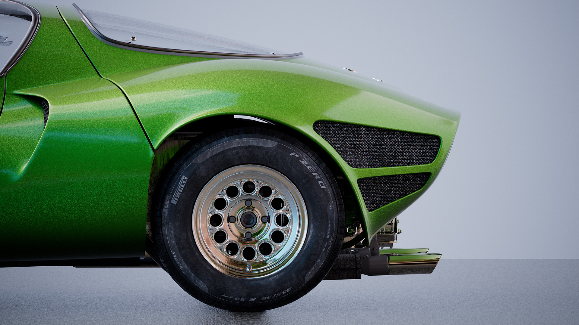
The flakes shader is a procedurally driven bump texture that creates a sparkly reflection effect that is helpful for creating materials like car paint, glitter, snow, sand, and some fabrics. This effect is created by randomly changing the orientation of each flake relative to the original objects surface normals, the higher the flake randomization the more prominent the flake pattern will appear as light hits each flake at a different angle than before.
Normal Maps in Blender
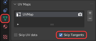
Calculating and exporting an object's tangents is a costly operation but it is necessary when using a normal map. Due to this performance cost all objects in Blender have the option 'Skip Tangents' enabled by default. This means that in order for normal maps to render correctly you must first disable the Skip Tangents option. Height field bump mapping will render correctly even when skip tangents is enabled.
Skip Tangents is an object level option that can be found in multiple places like the Object Data Properties panel under the UV Maps section and a Redshift shading node inside a UV relevant section. All of these areas are linked to one another per-object, changing the Skip Tangents option in any location affects the others.
|
|
| Skip Tangents option in Object Data Properties |
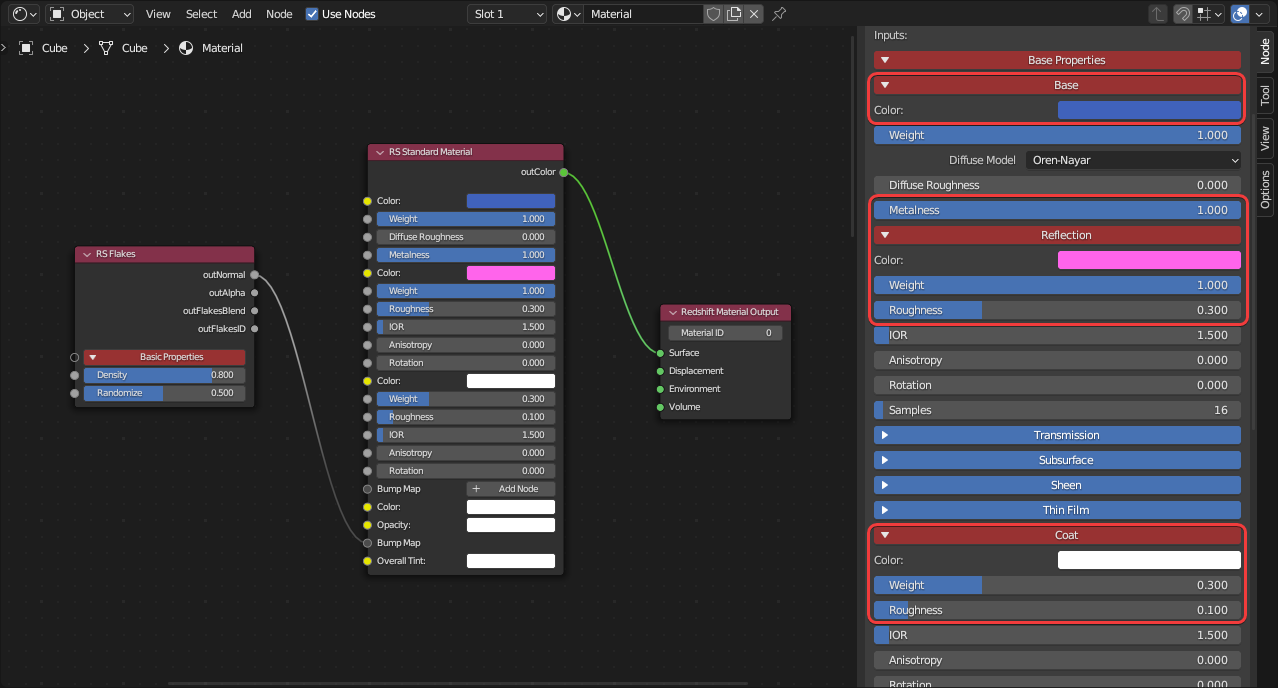
Connect the "Out Normal" of a flakes shader directly to a bump input on a material or bump blender - do not plug a flakes node into a Bump Map node the way you would a texture. The image below illustrates the correct way to connect a flakes shader to a standard material or blend flakes with another bump map texture.
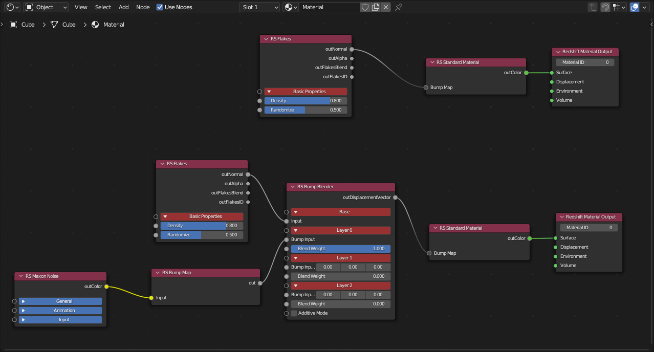
|
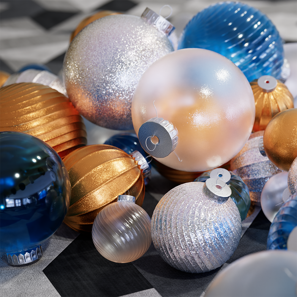
To make a simple metalic car paint material:
Create a Standard Material and connect the "Out Normal" of a flakes shader to the base Geometry > "Bump Map" input.
Set the Standard material's metalness to 1, this changes the reflectance from behaving like a dielectric material to a fully reflective metallic conductor. The base color now controls the car paint's primary color while the reflection color is used to tint reflections along the glancing angles of an object.
Increase the coat reflection weight and set the coat roughness to a low value to create a glossy clear coat look.
|
|
|
|
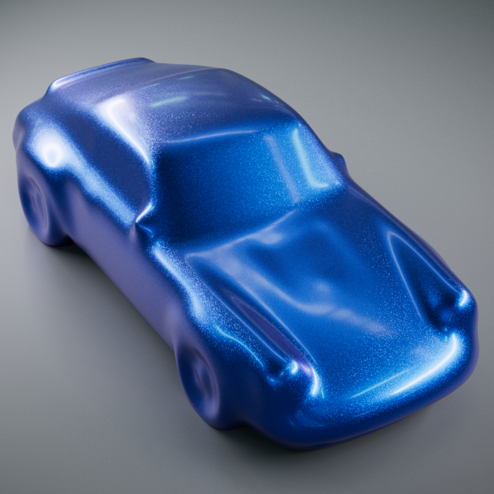
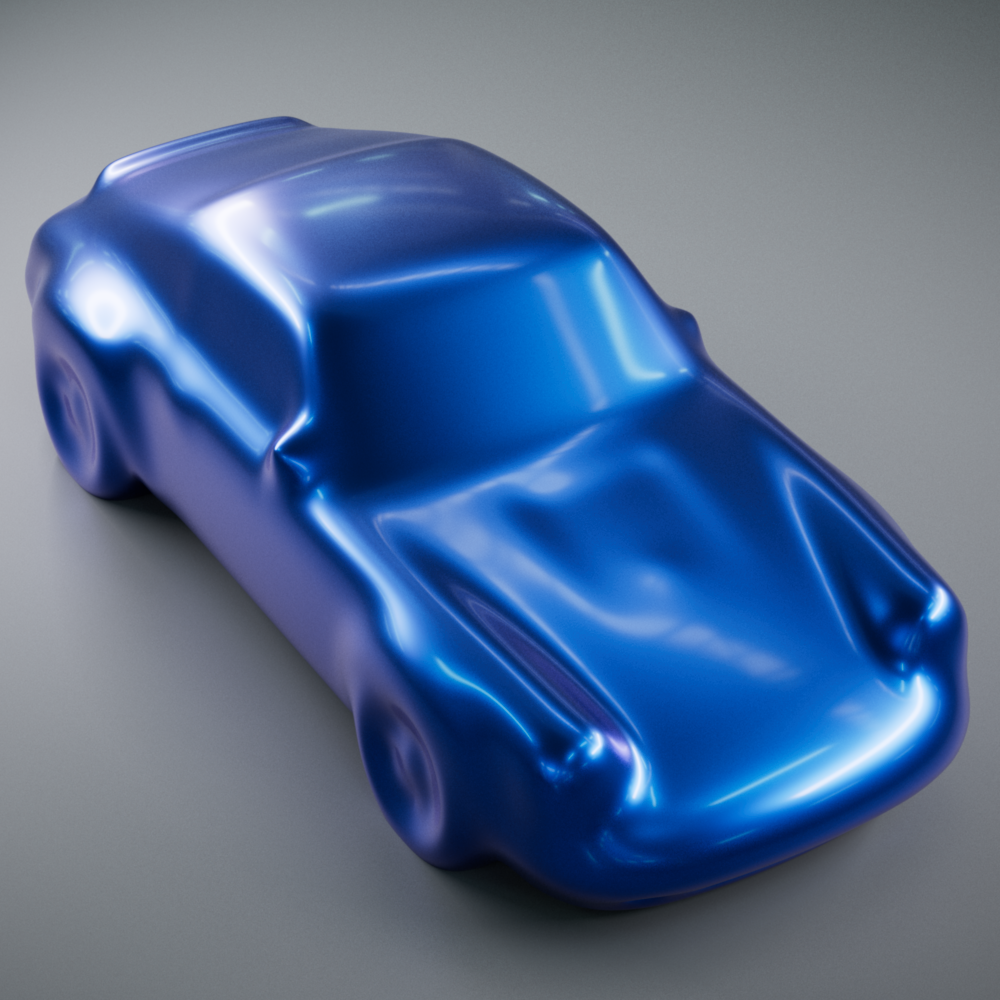
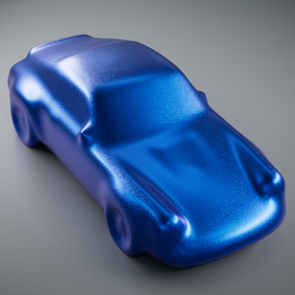
| Car Paint | Car Paint without Flakes | Car Paint without Clear Coat |
Car shape created from Szymon Kubicki's free model |
||
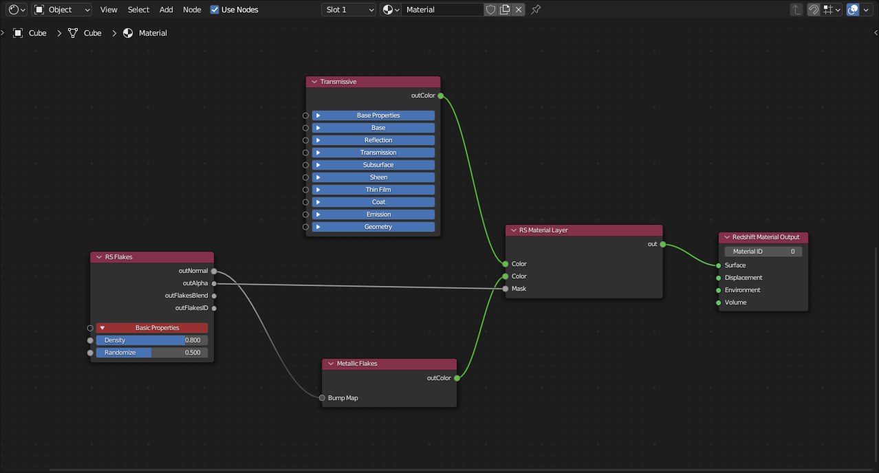
To create the appearance of flakes floating around inside a glass object:
Create a fully transmissive standard material and connect it to the "Base Material" of a Material Layer or Material Blender node.
Create a fully metallic standard material and connect it to the Layer 1 color of the Material Layer.
Create a flakes shader and connect its "Out Normal" to the base Geometry > "Bump Map" input.
Enable 3D flakes by increasing the depth parameter and adjusting the step size parameter according to your scene scale. Please see the 3D Flakes section for more information on these parameters.
Use the flakes "Out Alpha" to drive the Layer 1 Mask of the Material Layer.
|
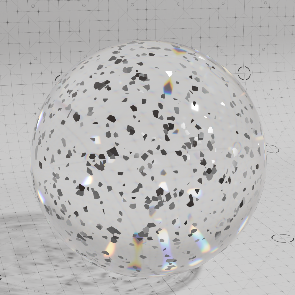
|
|
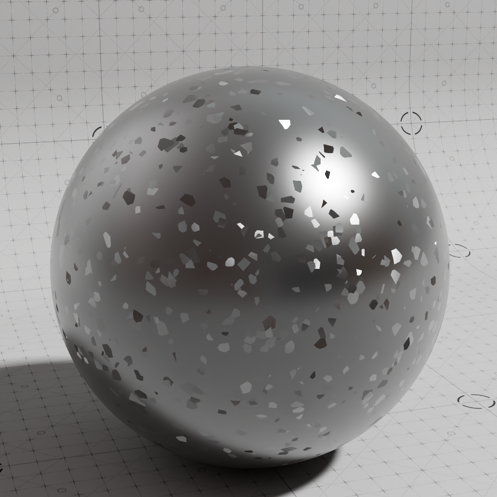
|
| 3D Flakes layered with Transmissive | Transmissive material solo | Metal 3D flakes material solo |
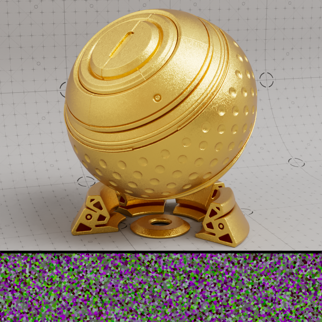
Use the "Out Flake ID" output to control the color of each flake by driving a gradient ramp and connecting it to the "Base Color" of a metallic Standard Material.

|
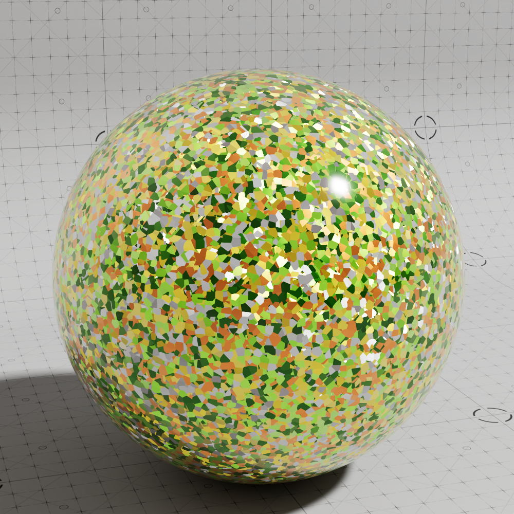
|
|
|
| Multicolored Flakes render | Flake ID Black and White | Flake ID remapped by gradient |
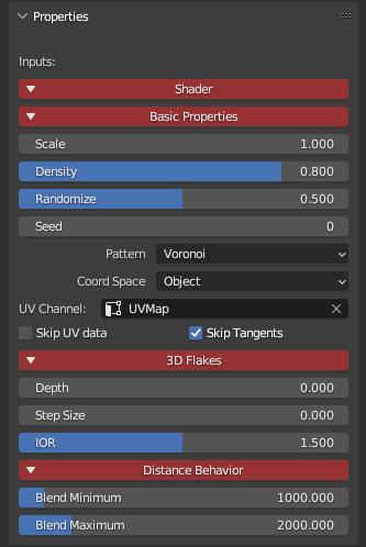
|
Controls the size of the flakes. Higher values result in larger flakes and lower values result in smaller flakes.
|
|
|
| Scale: 0.02 | 0.1 | 0.5 |
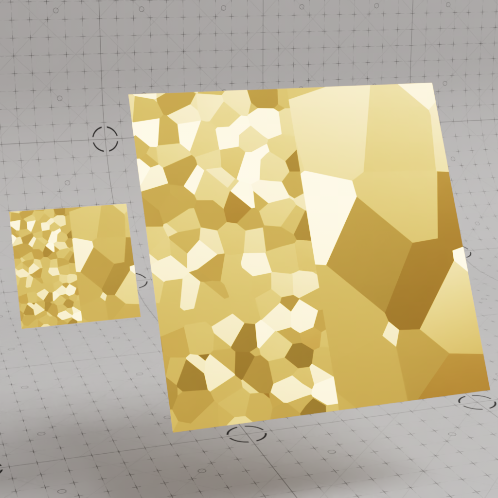
Controls the distribution of flakes across the surface. Higher values result in more densely packed flakes while lower values result in less dense flakes. This parameter accepts an input value between the range of 0 and 1, where 0 leads to no flakes being generated and 1 results in the entire surface being covered with flakes.
Density can also be driven by a texture, consider using something like a change range or scalar ramp node to more finely control the density of the flakes.

|
|
|
|
|
| Density: 0 | 0.25 | 0.5 | 1 | Textured |
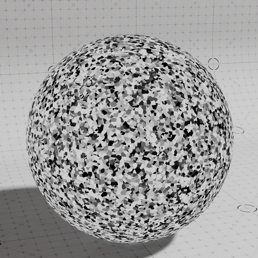
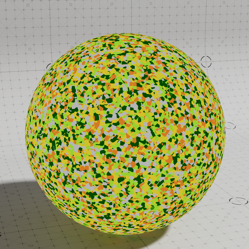
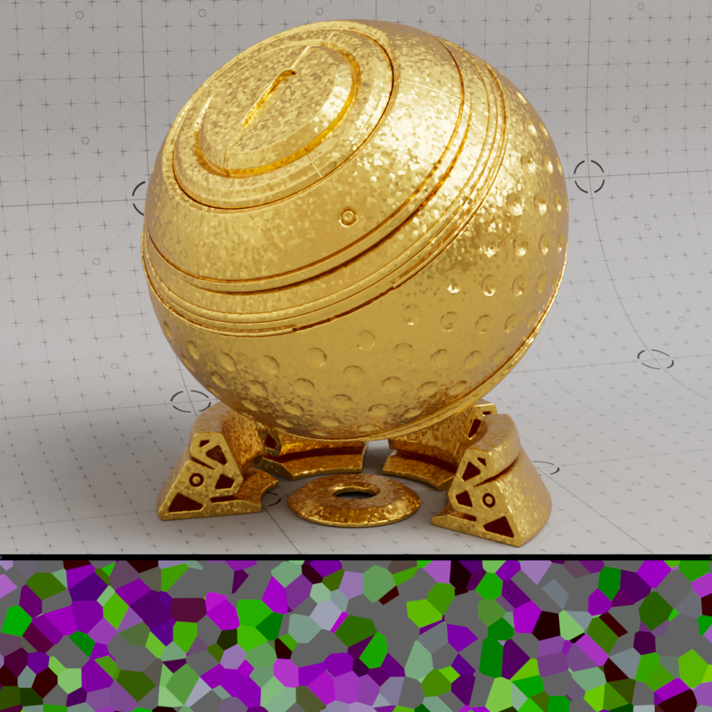
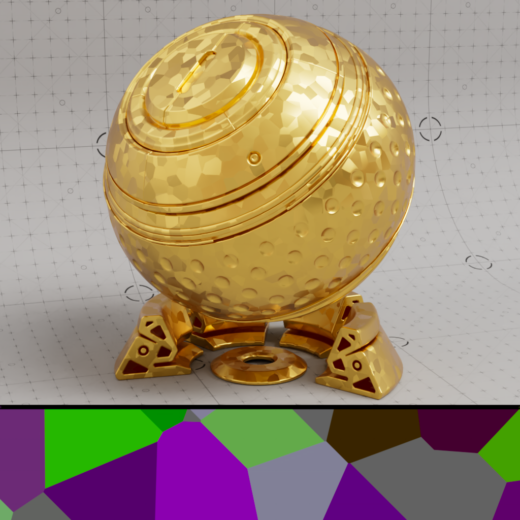
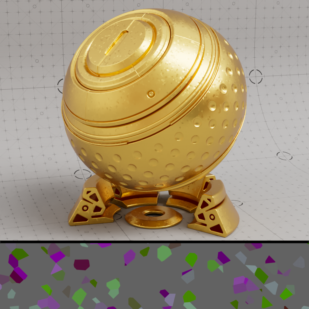
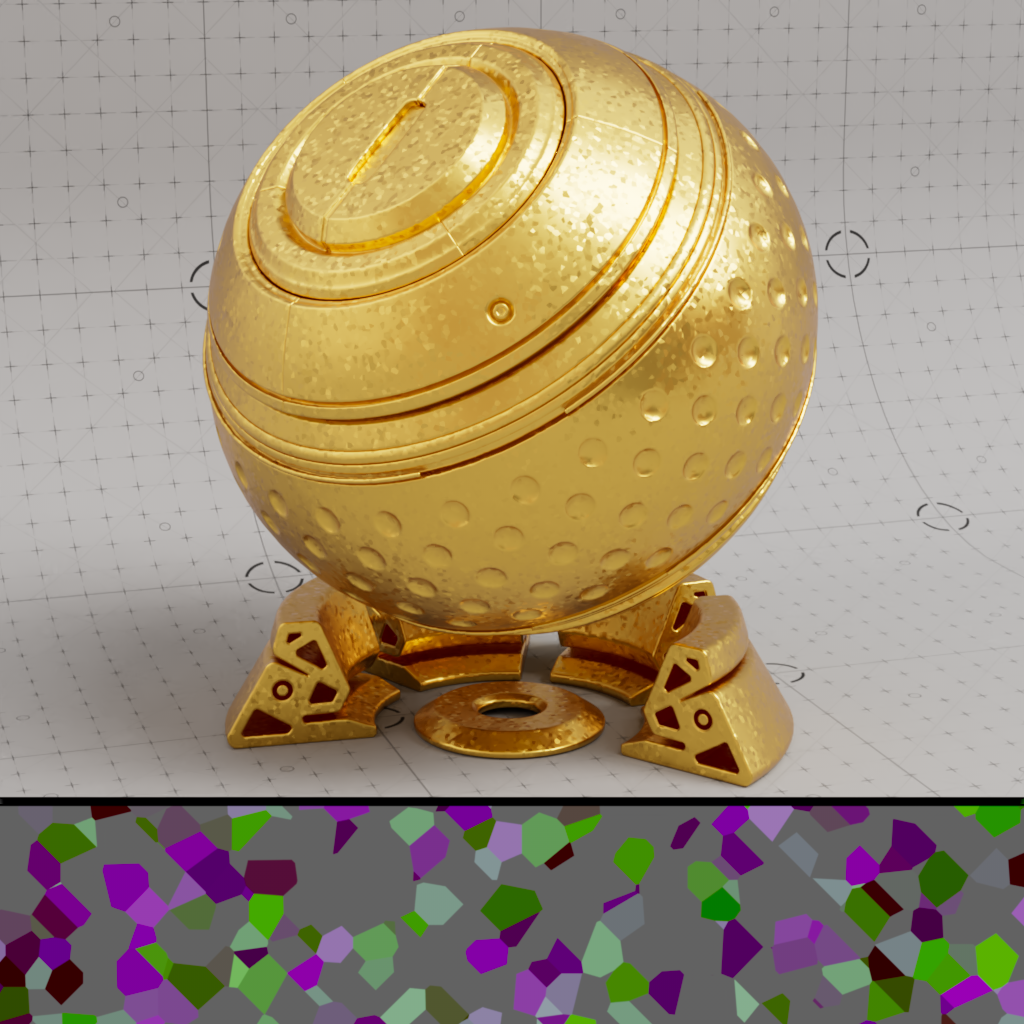
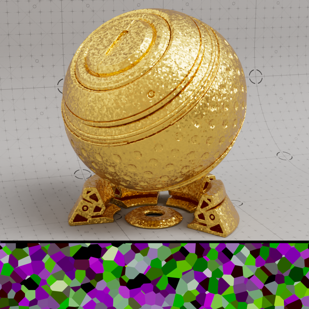
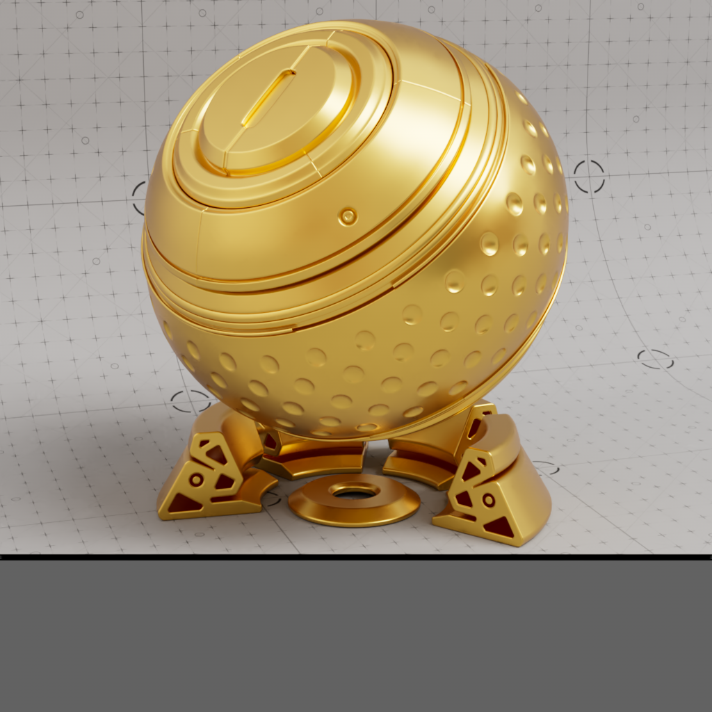
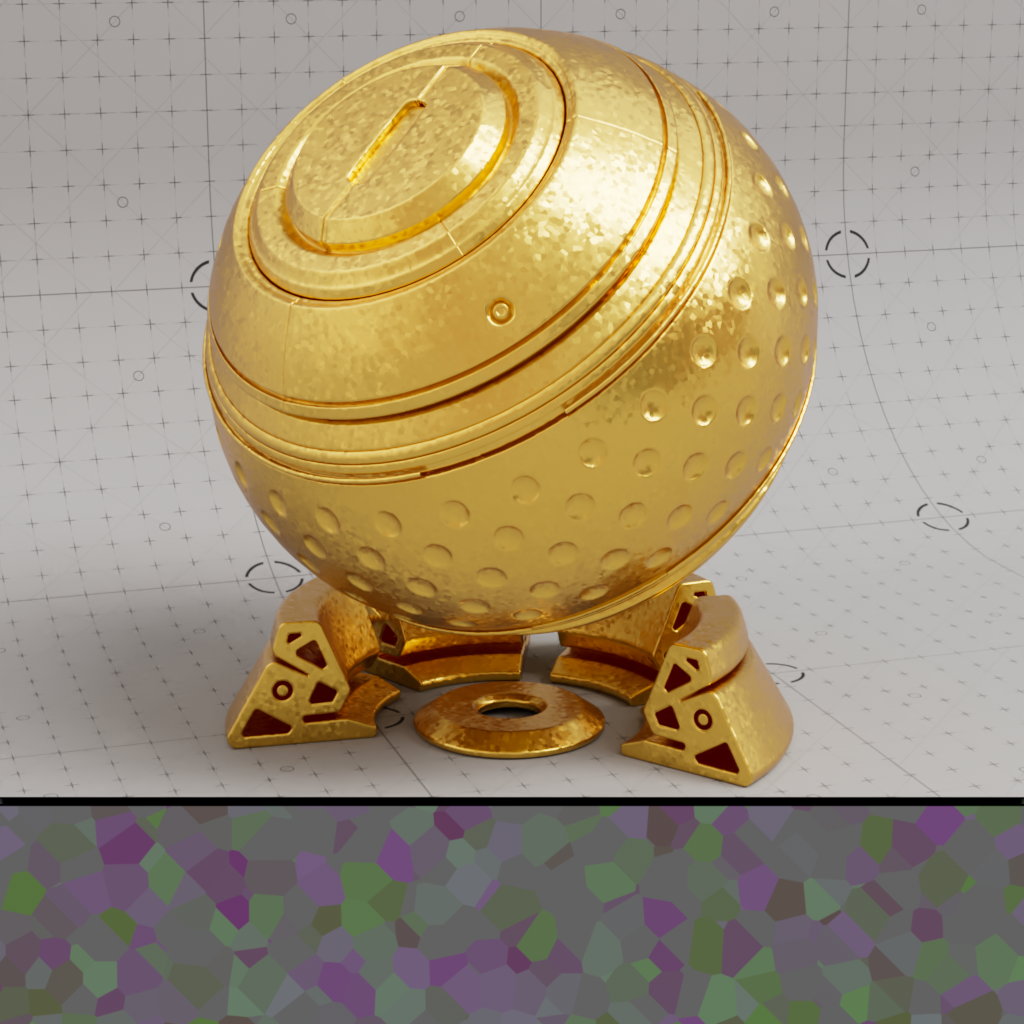
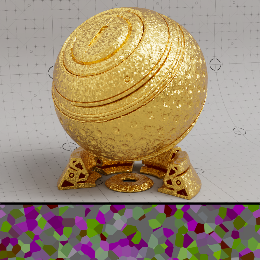
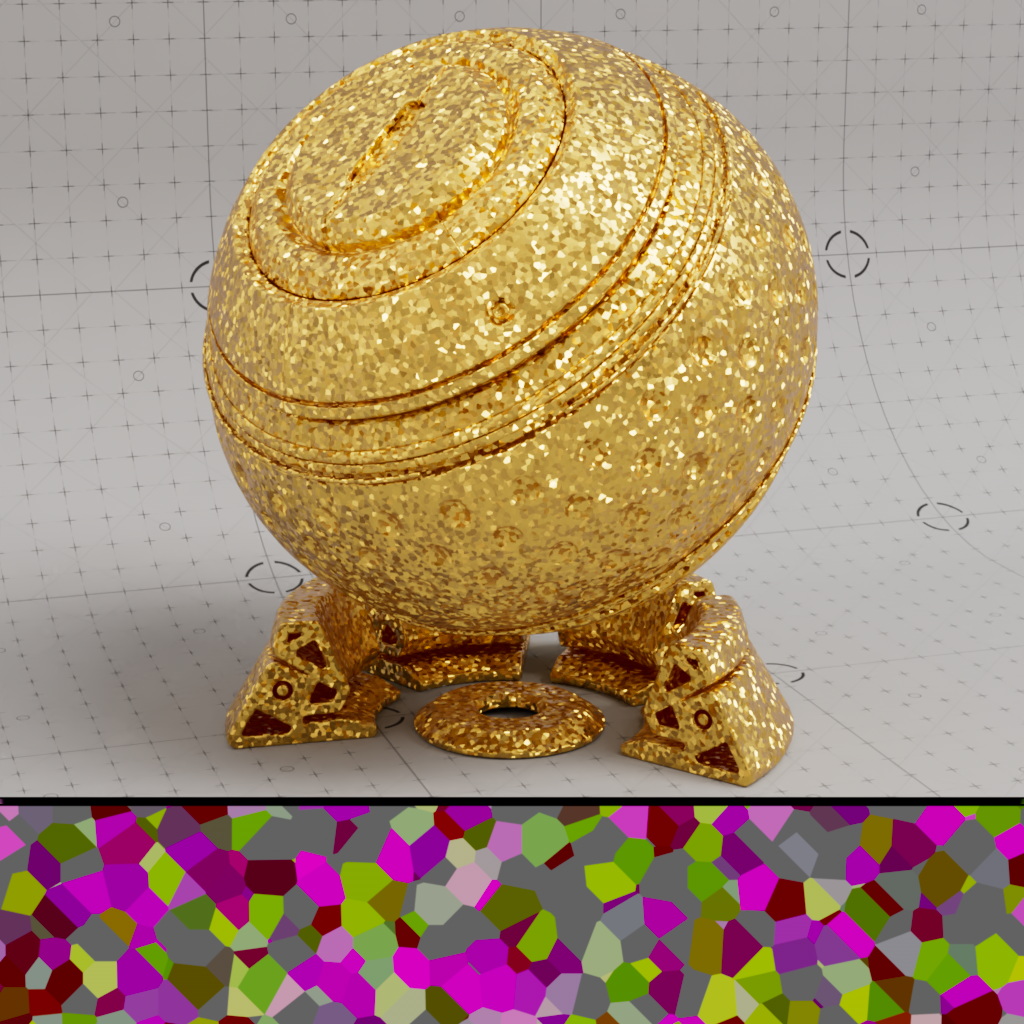
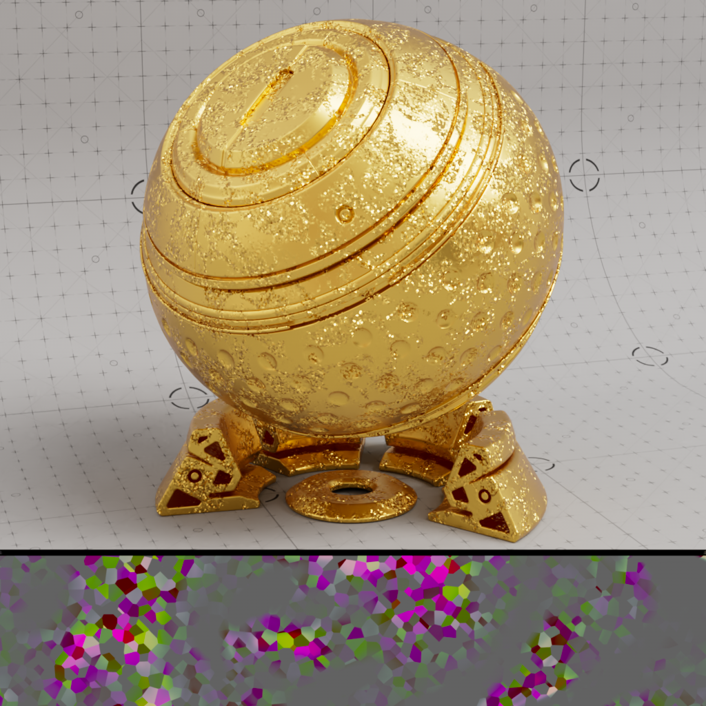
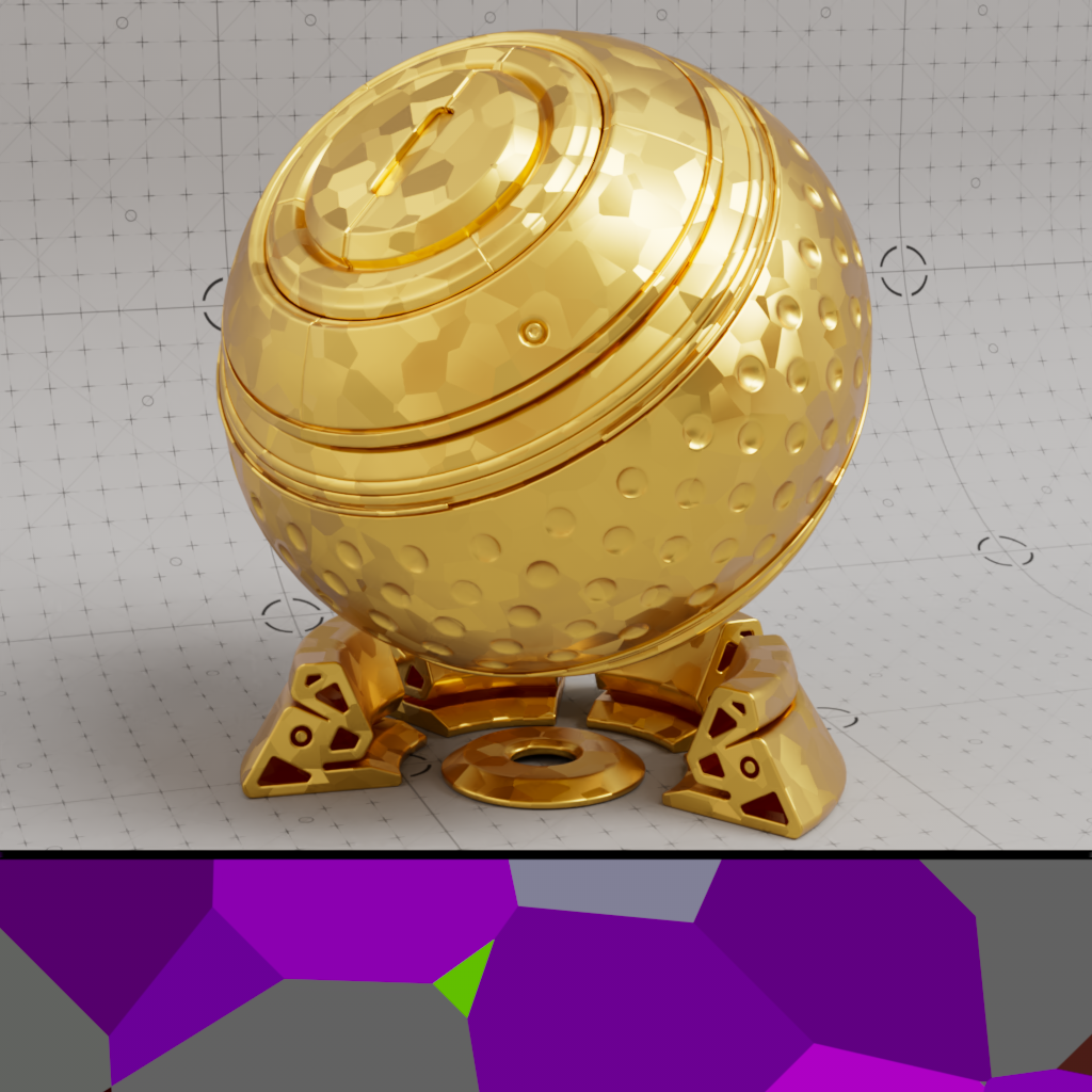
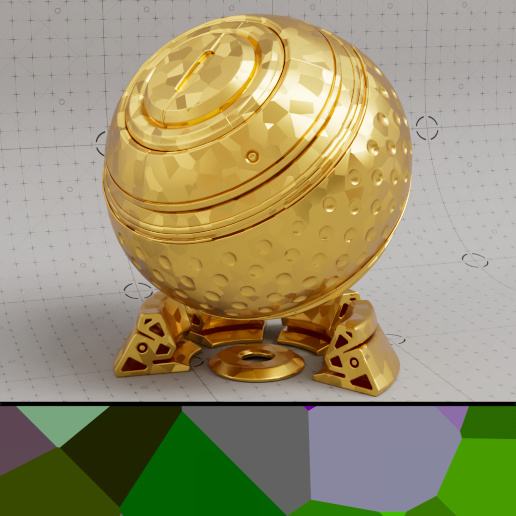
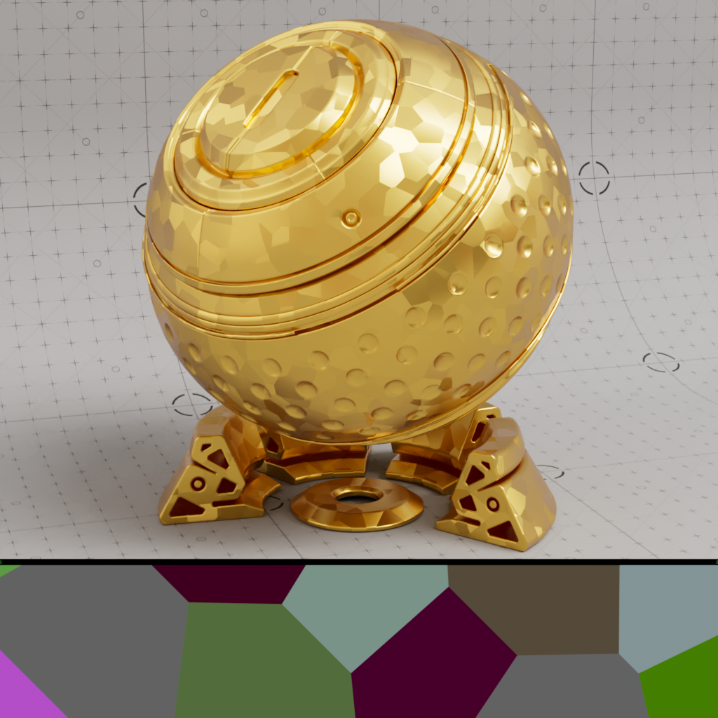
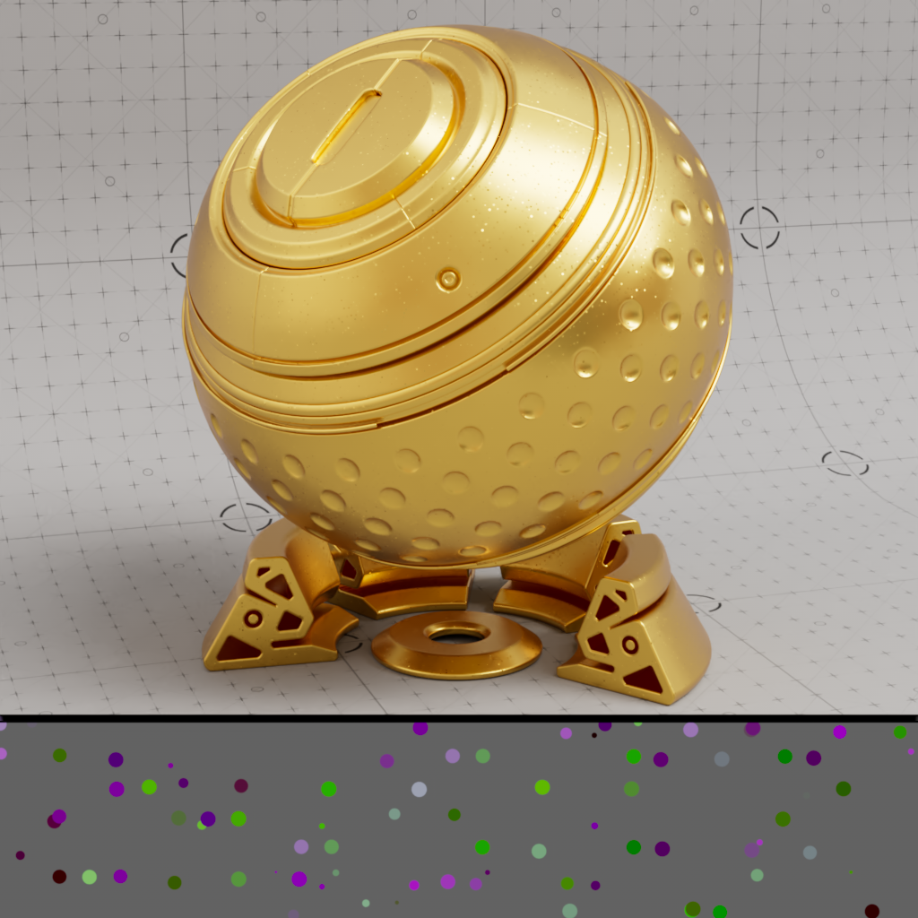
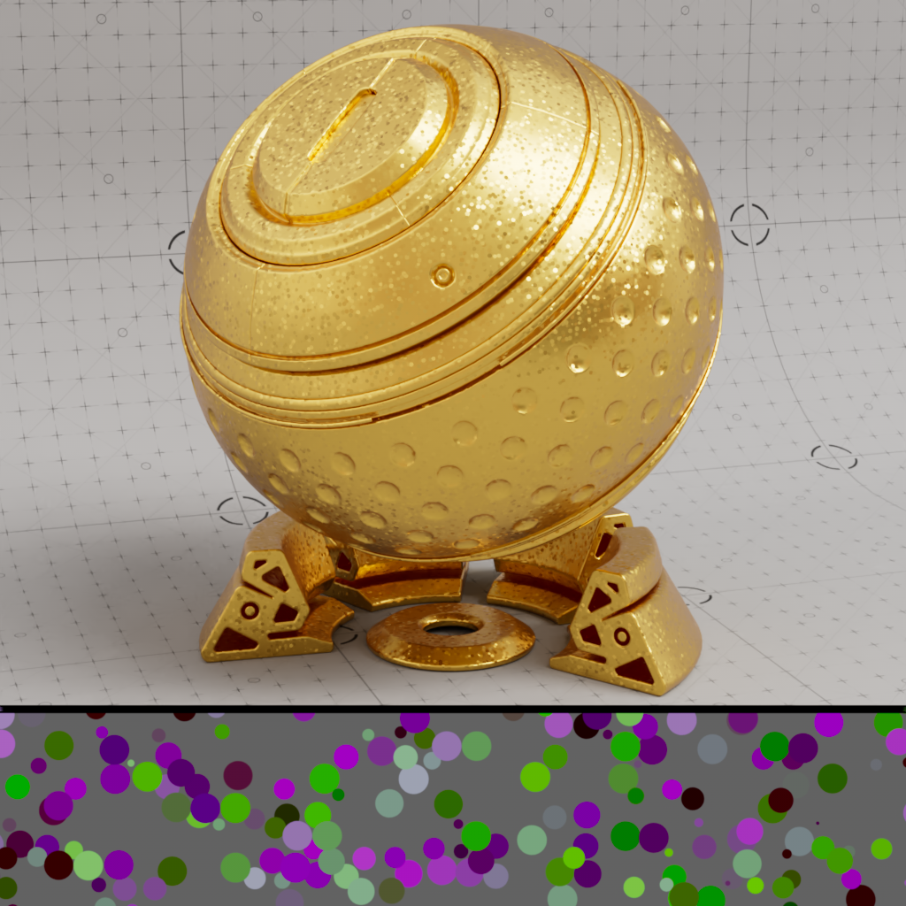
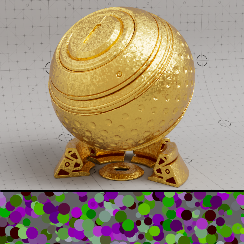
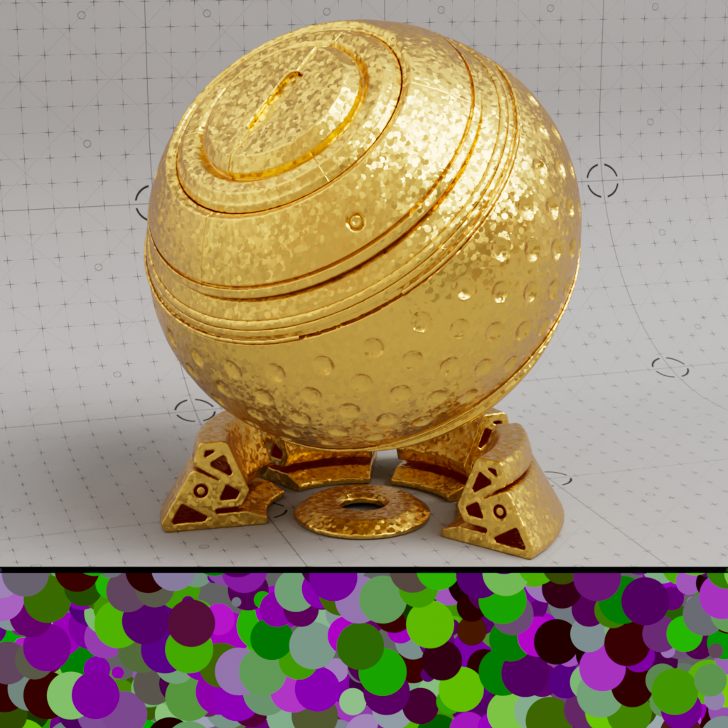
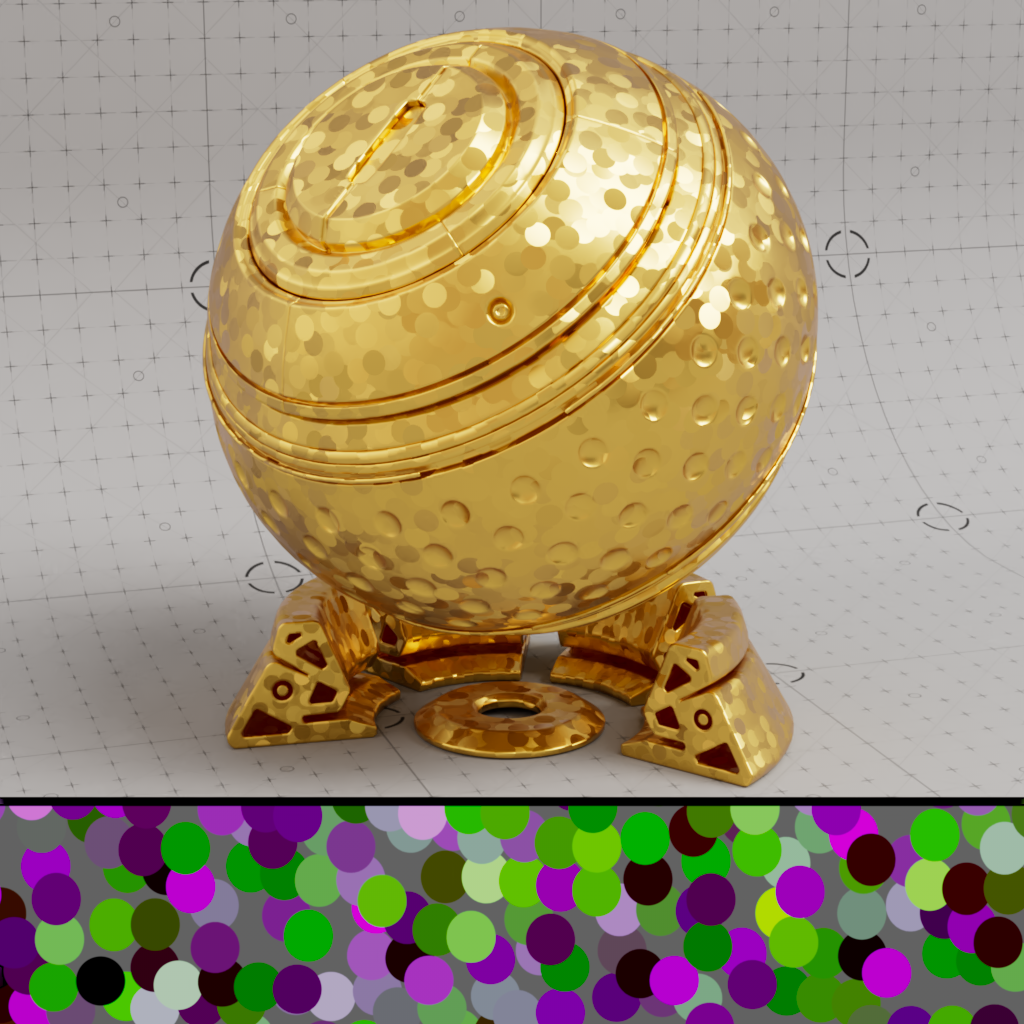
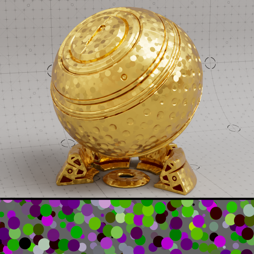
Controls how far the flakes are tilted away from the original surface normal. Higher randomization values result in flakes that are tilted farther away from the original surface normal, this results in more pronounced flakes because light is able to catch them from more extreme angles. When the randomization value is low the flakes will appear less prominent while a value of 0 results in no visible flakes since each flake perfectly matches the original surface normals.
Randomization can also be driven by a texture, consider using something like a change range or scalar ramp node to more finely control the flake randomization values.
The coloration of the flakes in the 2D portion of the example images illustrates the intensity of the randomization of each flake. The larger the difference in color between flakes the higher the difference in randomization compared to the original surface normal. Bright purple and green flakes represent flake randomization at its highest while flakes that are closer to grey represent little to no randomization.
|
|
|
|
|
| Randomize: 0 | 0.1 | 0.4 | 1 | Textured |
Controls the seed value used to drive the random position and orientation of the flakes.
|
|
|
| Seed: 0 | 1 | 2 |
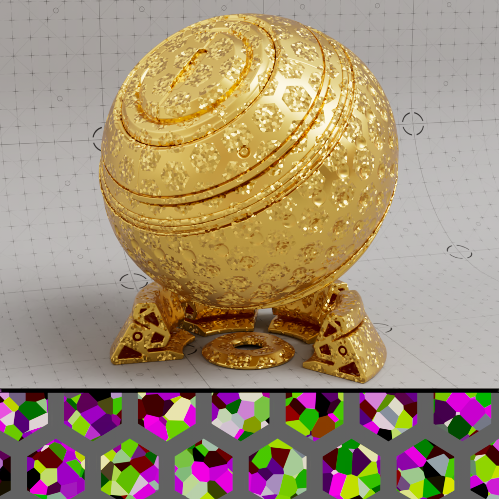
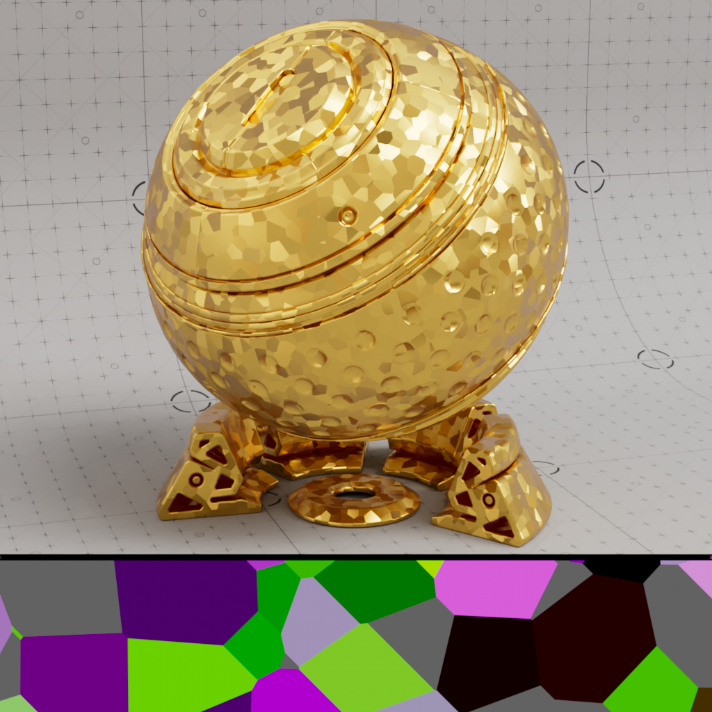
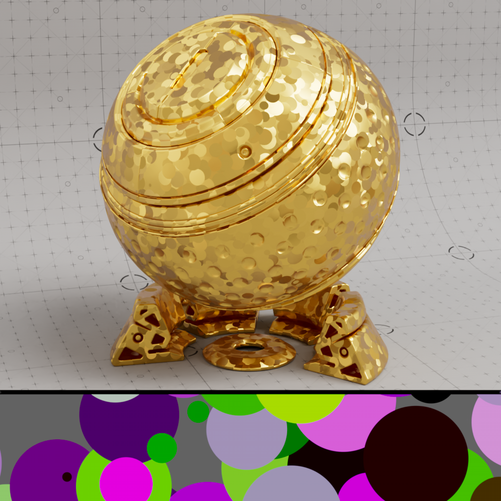
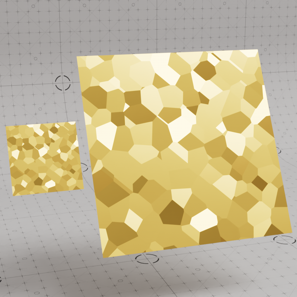
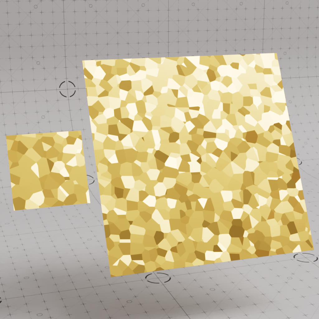
Controls the shape of the flakes.
|
|
| Pattern: Voronoi | Dots |
Only relevant when the dots pattern is used.
Controls the size of the dots.
|
|
|
|
|
Flakes Size: 0.25 |
0.5 | 0.75 | 1 |
Only relevant when the dots pattern and UV coordinate space are used.
Controls how much the dots vary in size. Higher values result in more varied flake size while lower values result in less variance, if the value is set to 0 all dots will have the same size.
|
|
|
Flakes Size Variance: 0 |
1 |
The coordinate space used to calculate the position and size of the flakes.
Object: The position and size of the flakes are relative to each object they are applied to.
World: The position and size of the flakes are relative to the world space. This will result in a consistent flake size across all objects however the flakes will swim if the objects are moved through the scene.
UV: An object's UVs are used to determine the position and size of the flakes, the scale and orientation of the UVs has a direct impact on the size and position of the flakes which can result in incongruous flakes across the surface.
|
|
|
| Coord Space: Object | World | UV |
Only relevant when the UV coordinate space is used.
This parameter defines which UV channel is used.
When disabled - by default, Blender processes an object's UV data. When enabled, Blender skips processing an object's UV data which stops features that require UV data from working correctly.
Skip UV Data must be disabled in order for the flakes shader to work properly.
When enabled - by default, Blender skips processing an object's tangent data which can be costly in order to improve performance. When disabled, Blender processes an object's tangent data which allows things like normal maps to function correctly.
Skip Tangents must be disabled in order for the flakes shader to work properly.
The flakes shader can be used to create a 3D effect that gives the impression that the flakes are layered on top of themselves complete with parallax. 3D flakes are calculated using ray marching and the look can be controlled by the parameters covered below. Please see the 3D Flakes in Glass example to see how to set up this effect.
| 3D Flakes | 2D Flakes |
Controls the maximum ray marching depth in scene units that is used to calculate the position of 3D flakes.
Higher values allow 3D flakes to appear deeper beneath the surface of an object while lower values will limit the flakes closer to the surface. When depth is 0, no 3D flakes are rendered. The sphere used in the example images has a 10 unit radius so a depth value of 20 allows the rays to travel all the way through it.
| Depth: 0 | 1 | 5 | 20 |
Controls the distance of each step in scene units that is used for the ray marching calculation of 3D flakes, this has a large impact on how many 3D flakes are visible and overall performance. The number of flake layers is determined by dividing the depth value by the step size. For example, if depth is 6 and the step size is 1 (6 / 1 = 6) then there will be more flakes than when the step size is 3 (6 / 3 = 2).
In general lower values will result in more flakes while higher values result in fewer flakes. If the step size is 0 or larger than the depth value itself then no 3D flakes are rendered. Using a very low step size can have a negative impact on render times.
| Step Size: 0 | 0.5 | 1 | 3 |
Controls how the 3D flakes are refracted.
| IOR: 1 | 1.5 | 2 | 3 |
The following parameters control how the flakes appear at a distance, this is helpful because flakes can flicker and look like aliasing when they are smaller than individual pixels. For example, an object with flakes may look aliased when far away because the number of flakes per-pixel is naturally higher than an object that is closer to the camera. To limit this side effect the randomization of flakes can be faded out based on an estimated number of flakes per-pixel, the points where the flakes fade in and out are controlled by the Blend Minimum and Blend Maximum values covered below. The larger the range between the blend minimum and blend maximum the smoother and more gradual the flakes blend in and out, this can be seen in the example images below where a heat map is used to illustrate the blend between the minimum (red) and the maximum (blue) ranges.
Anything that could alter the estimated number of flakes per-pixel can have an impact on how the flakes appear. For example, making flakes smaller with the flake scale parameter or rendering at a lower resolution will increase the flakes per-pixel estimation which pushes the number of flakes per-pixel closer to the Blend Maximum in which flakes will no longer be visible. Even changing the camera angle or rotation of an object can change the estimated number of flakes per-pixel.
Controls the start point of the flake fade out.
If the estimated number of flakes per-pixel is below this value then flakes are rendered normally.
If the number of flakes is above this value then the flakes begin to fade out until they reach the Blend Maximum value where they will no longer be visible.
| Blend Minimum: 0.1 Blend Maximum: 5 |
2 | 4 |
Controls the end point of the flake fade out.
If the number of flakes per-pixel is below this value they will fade in until they reach the Blend Minimum value where they will be rendered normally.
If the estimated number of flakes per-pixel is above this value they will no longer be visible because the flake randomization value will be reduced to 0.
| Blend Maximum: 2.1 Blend Minimum: 2 |
5 | 20 |
The displaced surface normal for the flakes shader. This is the primary output for a flakes shader and can be plugged into the Bump Map input of a Standard Material or other bump input.
An output mask for the flakes, all flakes will appear white with a value of 1 and anywhere there are no flakes will appear black with a value of 0.
If the flake density is set to 1 then the entire mask will appear white since the whole surface will be covered with flakes.
A greyscale output that represents the distance-based blending between the flakes and the surface normal.
A greyscale output that identifies each flake. This can be used, for example, to drive a gradient ramp and control the color per-flake, for more information please see the multicolored flakes example.