UV Context Projection
Overview

|

|
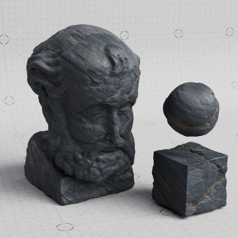
| Scene by Saul Espinosa Textures from PolyHaven.com |
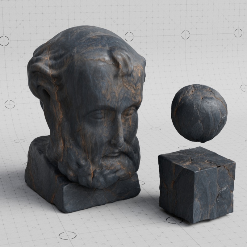
Scene by Saul Espinosa Ground texture from AmbientCG.com |
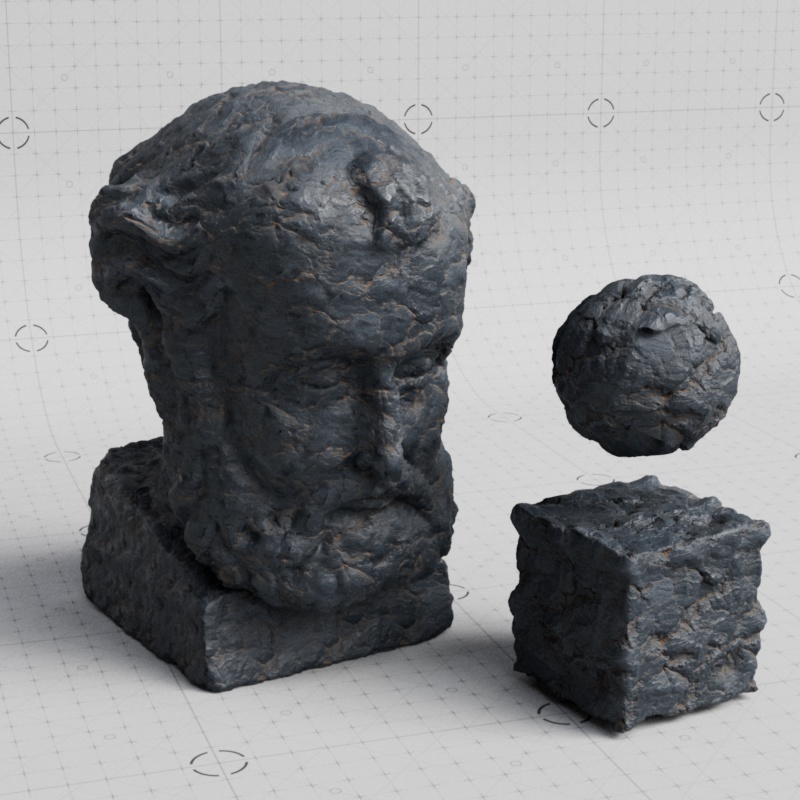
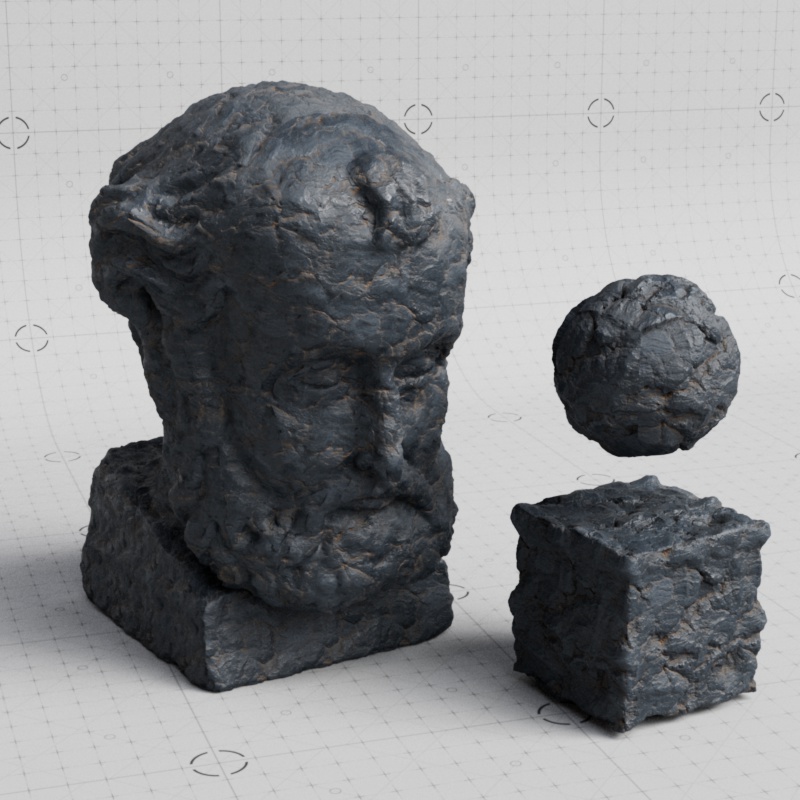
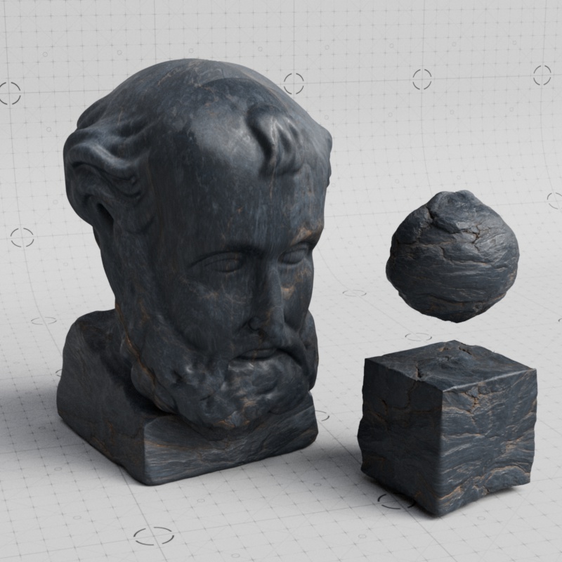
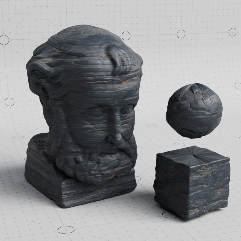
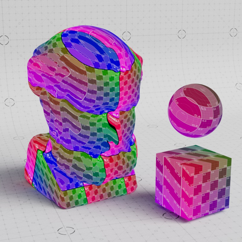
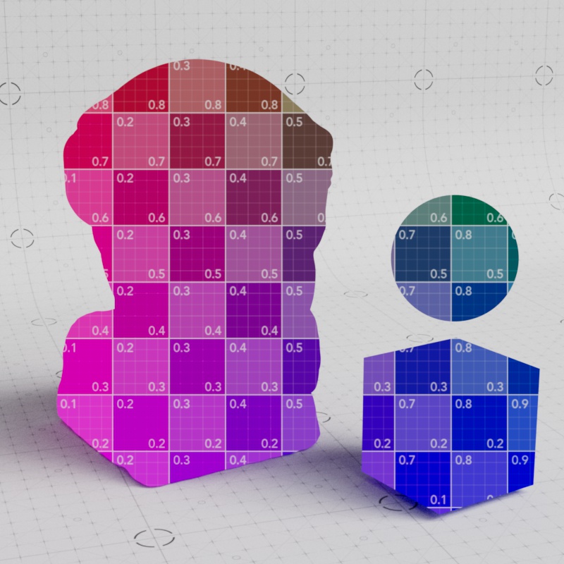
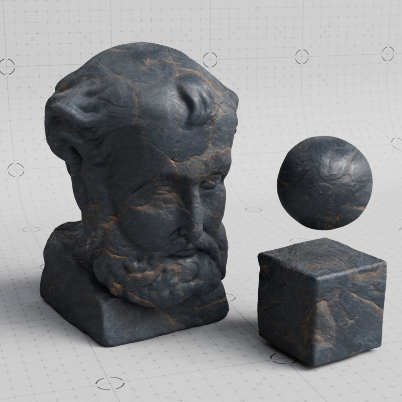
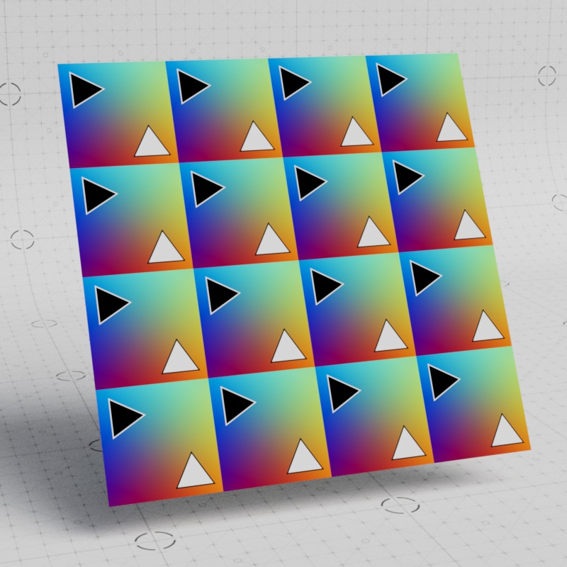
The UV Context Projection is a powerful utility node that applies the same mapping across all the textures connected to a material. Most materials are built using a set of textures that only look good when they perfectly match up with each other. The UV Context Projection node makes it easy to adjust all textures and keep them in sync. This includes procedural textures that use UVs like the Redshift Tiles shader.
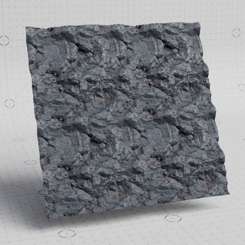
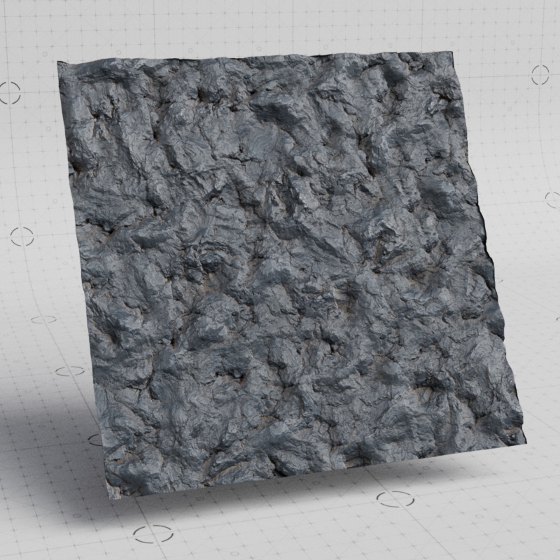
In addition, Hex tiling can be enabled for quick seamless texture tiling. Great for adding variation across large surfaces. Procedural textures are not compatible with Hex tiling.
| Adjusting a material using UV Context | Using Hex Tiling with UV Context |
| Textures from PolyHaven.com | |
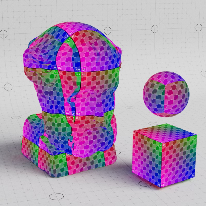
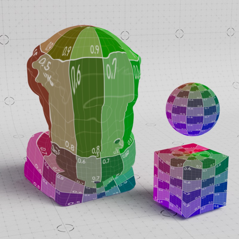
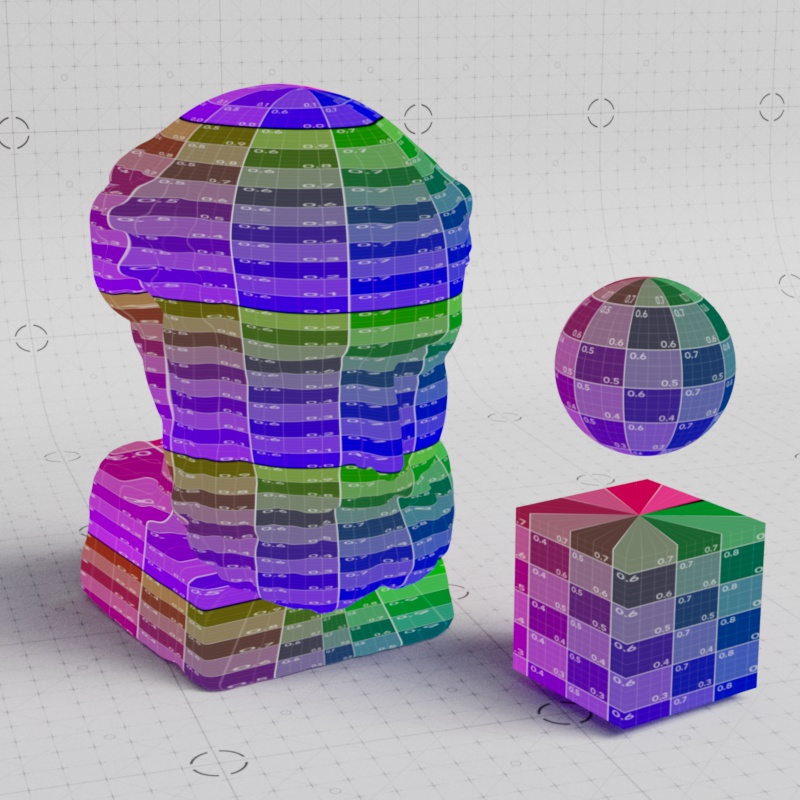
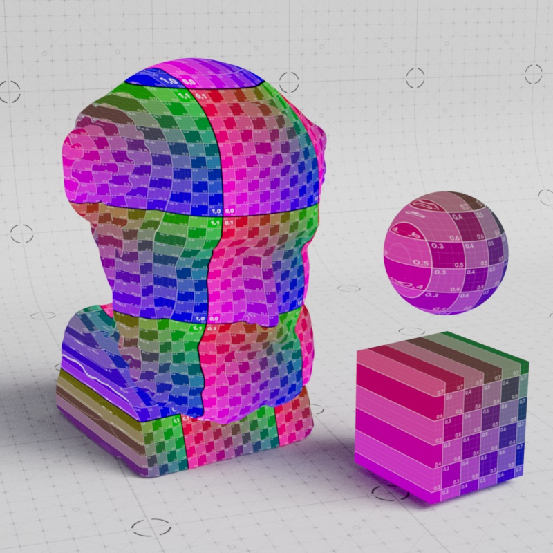
All the textures can use an object's UV set or be switched to a number of other UV projections like Tri-Planar, Spherical, or Flat.
| Changing the Projection type using UV Context |
| Textures from PolyHaven.com |
The UV Context Projection node requires constant inputs. For example, you cannot drive the UV Context Projection node's Transform Offset with a Maxon Noise or Jitter node the way you can on a Texture Sampler.
Examples
How it works
UV Context port: Direct or Downstream connections
Using a UV Context Projection node is as simple as connecting the OutContext to a node with a "UV Context" port.
There are two ways for a texture to receive texture mapping information, from either a direct connection or a downstream connection.
-
Direct connections: When a UV Context node is connected directly to a texture's UV Context port. This takes precedence over any downstream connection, serving as a local override.
-
Downstream connections: When an upstream texture automatically inherits mapping information from a UV Context node connected downstream in the shading graph.
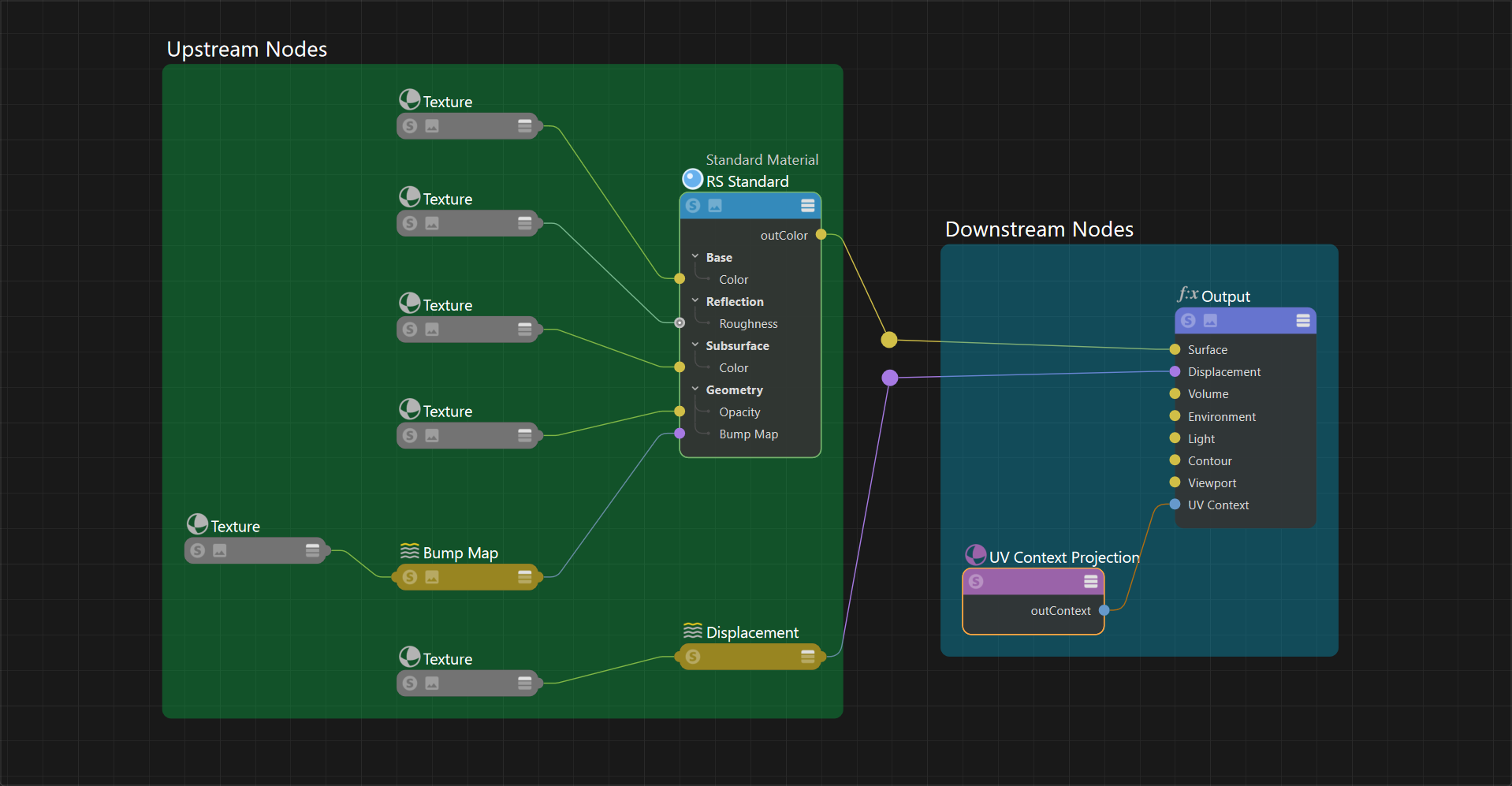
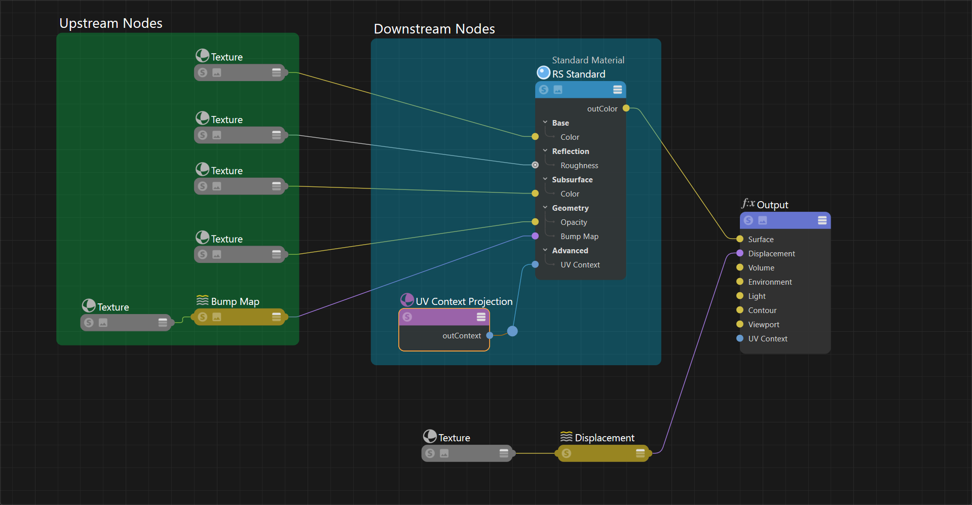
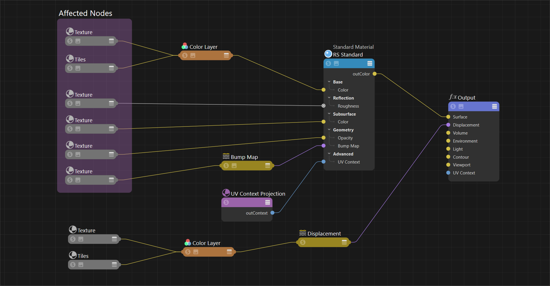
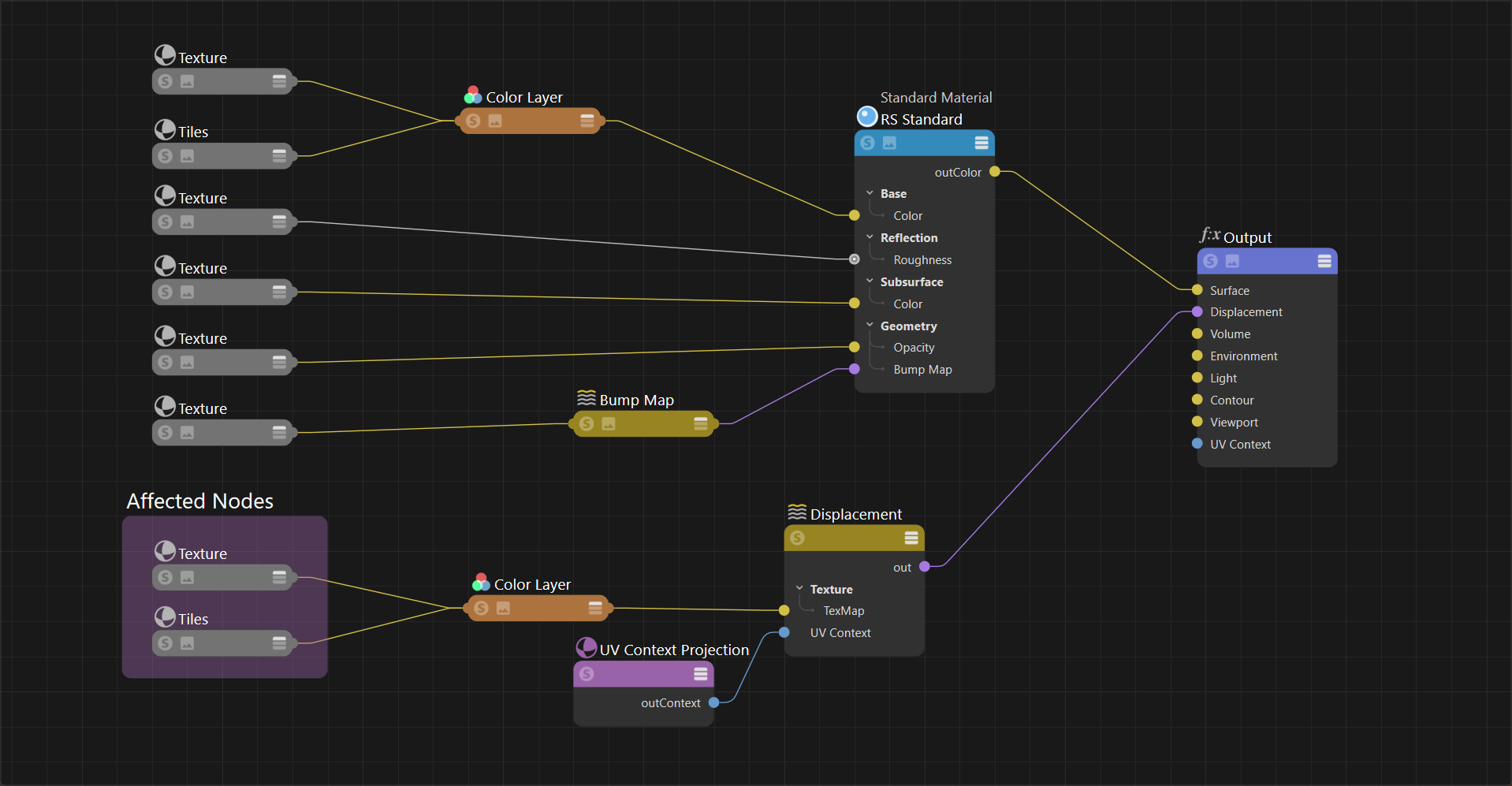
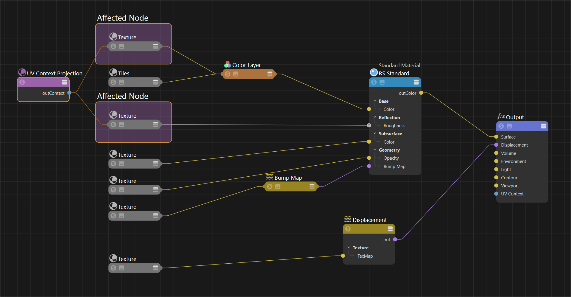
Thanks to downstream connections you don't need to manually sync each texture that should have the same mapping. That's because upstream textures are designed to automatically inherit UV Context information connected downstream in the shading graph. In the examples below, note how changing where the Context Projection node is connected affects which nodes are considered upstream. In the second example, there is no UV Context Projection node downstream from the displacement texture so it is no longer affected.
|
|
| Downstream connections UV Context Projection connected to the Material Output node All textures connected to the Material and Displacement shaders are upstream |
Downstream connections UV Context Projection connected to the Material shader node Only the textures connected to the Material shader are upstream |
Alternatively, a UV Context node can be connected directly to a texture which overrides any downstream connections.
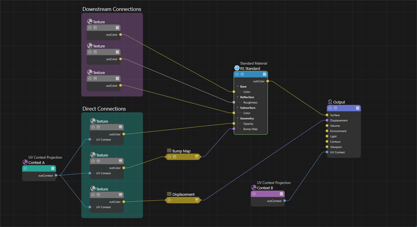
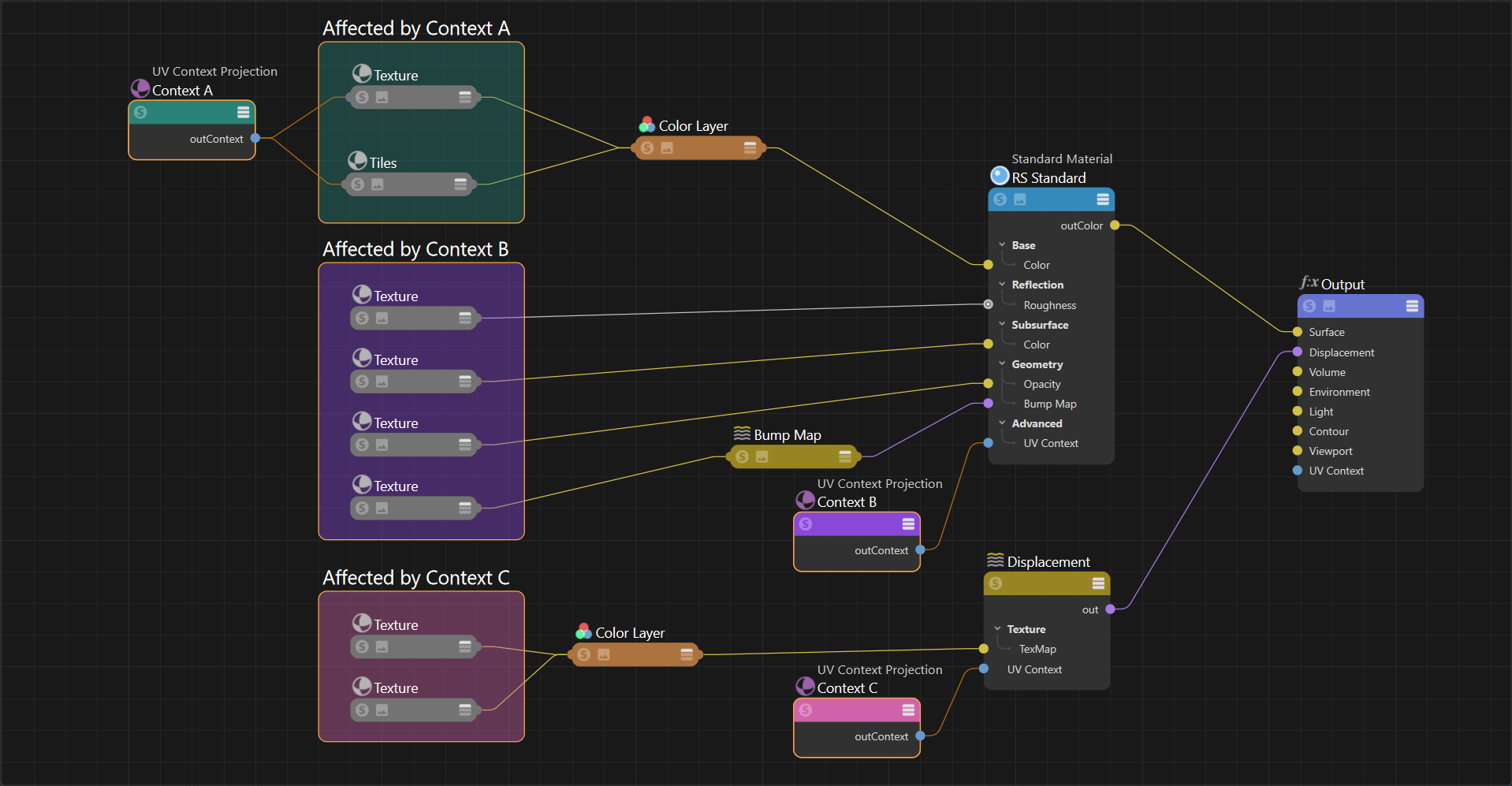
Use downstream connections whenever possible to keep a shader graph simple, using direct connections only where necessary. However, it's possible to use direct connections on every texture and get the same result, it just requires more manual setup.
|
| Direct and Downstream connections UV Context Projection A connected to the Material Output node UV Context Projection B connected directly to three textures, overriding the downstream connection |
Textures that support a direct UV Context connection:
- Brick
- Flakes
- Pavement
- Maxon Noise
- Scalar Ramp
- Ramp
- Tiles
- Texture Sampler
Nodes with a UV Context Port that enable downstream connections to all connected textures:
- OpenPBR Material
- Standard Material
- Displacement shader
Connection examples
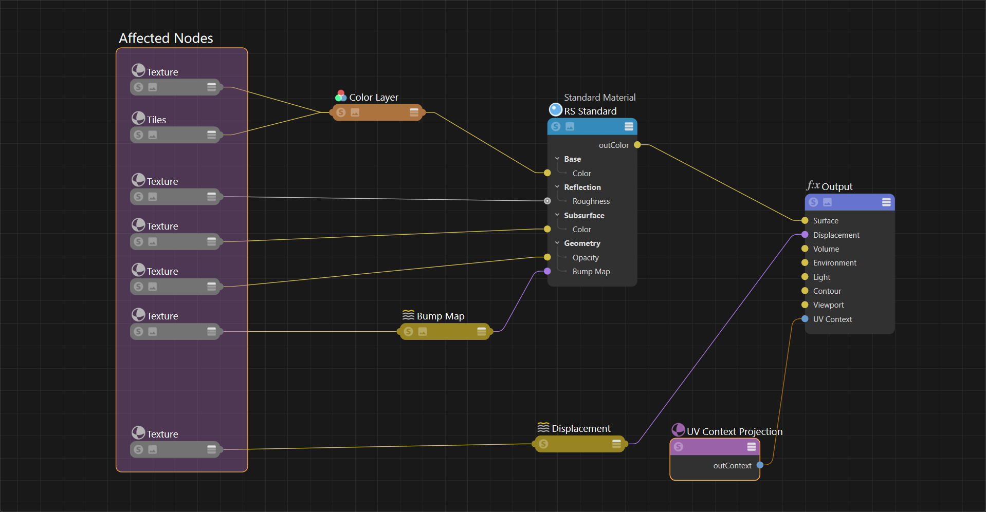
The simplest UV Context setup is one where it affects all textures in a material, including the displacement textures. This is accomplished by connecting one Context Projection node to the Material Output so it affects all upstream textures.
|
| UV Context Projection connected to Material Output |
Alternatively you could have a UV Context Projection node for only the Material textures or only the Displacement textures.
|
|
| UV Context Projection connected to Material | UV Context Projection connected to Displacement |
Direct connections are useful when you have some textures that need to stay in sync but are different from the rest of the material. That's as easy as connecting a UV Context Projection node directly to the texture's own UV Context Port - a directly connected texture always takes precedence over any downstream inheritance.
|
|
| UV Context Projection connected directly to two textures | Mixing direct and downstream connections |
When blending multiple materials, consider using a single UV Context Projection node for each material. In the example below, Context A is used for Material 1 and Context B is used for Material 2. Since displacement textures don't connect to the material directly you can connect the Context nodes directly to the textures to keep them in sync with their material.
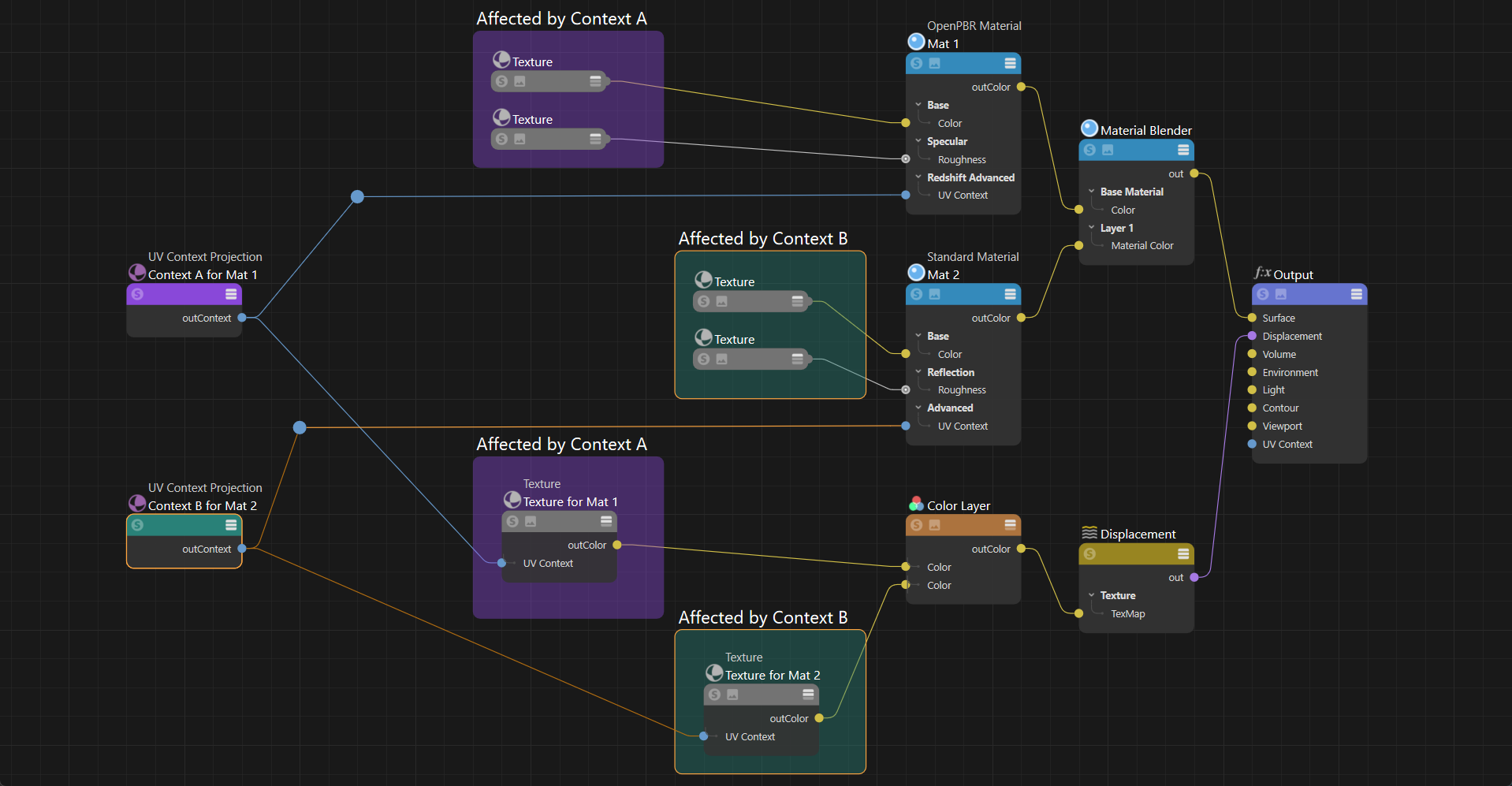
|
| Using different UV Context nodes for different materials |
Adding Randomization
The ports of a UV Context Projection node only allow a constant input, meaning nodes like a texture and jitter cannot drive its parameters. However the UV adjustment options on individual nodes still work in combination with a UV Context connection. This allows you to connect a jitter node to the Offset and Rotate of a texture node to add randomization to your material and still control overall texture placement using the UV Context Projection node.
The example graph below uses a jitter node to add variety to the base color and roughness of the marble texture on each object and still use a UV Context Projection node to control those textures using a downstream connection.

|
| Adding jitter randomization | Controlling overall rotation with UV Context Projection |
Placing a texture using an object
The UV Context Projection node can be used to place a texture in a scene with precision. In this example a graffiti material with the word "Cool" is placed on a brick wall material. There are two UV Context Projection nodes in use, one is used for the Brick material while the other is used for the cool material. The brick material requires displacement so it uses a UV Context node in Tri-planar mode connected downstream in the shader graph, this way the brick material and the brick's displacement textures inherit the UV mapping.
The cool material uses a UV Context node in the Flat projection mode using the "world" projection space. Then the Transform Space is set to "Object" and an object is selected using the "Object Picker." This allows the object to be referenced in world space which makes placing the projection of the graffiti texture very easy in the scene.

|
With everything in sync, the graffiti can be moved around the scene and it appears as if projected onto the brick surface at the same spot as the object driving the transform source. In the examples below, the floating gizmo object is used as the picked object to define its transform coordinates in world space.
| Moving the graffiti | Scaling the graffiti |
Parameters
UV Source
Projection
Controls how the textures are projected onto the surface from the following options:
- Passthrough
Passthrough is the default projection method, it passes along the UVs it receives from the DCC to Redshift.
- UV Channel
Uses an object's UV coordinates with the ability to specify a specific UV set using the "UV Channel" field below. By default, when the path is left blank, the result is the same as "Passthrough"
|
|
| UV Channel UV Texture Reference |
UV Channel PBR Material |
- Tri-Planar
Uses a tri-planar projection for the textures. The textures are projected from the X, Y, and Z axes and blended across the object based on the angle of the surface. This is great for quickly applying a nice projection across a complex surface and the blending can be adjusted and distorted using specialized controls.
Doesn't work with stacked or blended materials.
|
|
| Tri-Planar UV Texture Reference |
Tri-Planar PBR Material |
- Cubic
Similar to a Tri-planar projection but without the blending and distortion options.
|
|
| Cubic UV Texture Reference |
Cubic PBR Material |
- Spherical
Textures are projected onto the object using a spherical shape.
|
|
| Spherical UV Texture Reference |
Spherical PBR Material |
- Cylindrical
Textures are projected onto the object using a cylindrical shape.
|
|
| Cylindrical UV Texture Reference |
Cylindrical PBR Material |
- Flat
Textures are projected onto the object using the shape of a plane, making it great for flat objects and decals. However, this results in stretching on parts of the surface that are not perpendicular with the projection plane.
|

|
| Flat UV Texture Reference |
Flat PBR Material |
- Spatial
Similar to Flat projection, but now the textures are not simply projected straight, but at an angle (to the left and upwards for frontal views).
|
|
| Spatial UV Texture Reference |
Spatial PBR Material |
- Shrinkwrap
A unique style of projection that pins the textures at the top of the sphere (north pole) and the rest is pulled down over the sphere and pinches at the bottom (south pole). The advantage with shrinkwrap is that, compared to the spherical projection, there is only a seam on the bottom rather than the top and bottom.
|
|
| Shrinkwrap UV Texture Reference |
Shrinkwrap PBR Material |
- Camera
Maps textures onto an object based on a cameras perspective.
When using Camera projection, you must define the projection camera by selecting one in the "Object Picker" field. This is found in the Coordinates section of the UV Context Projection node. You can select the render camera or any other camera in the scene.
|
|
| Camera UV Texture Reference |
Camera PBR Material |
UV Channel
Only available when using "UV Channel" projection.
Enter the name of a specific UV channel to control how the texture is applied. By default, when left blank, Redshift uses the default UV data provided by the DCC.
Projection Space
Sets the projection space from the following options:
- World: Uses the world-space coordinates. If the object moves or deforms the textures will swim.
- Object: Uses the object's coordinate space. If the object moves, the textures will not swim. If the object deforms the textures will swim.
- Reference Object: (Default) Uses a reference object's coordinate space. With an appropriate reference object, if the object moves or deforms the textures will not swim. Redshift tries to automatically find the correct reference object.
- This option also projects the textures before displacement, this ensures that the base color and other textures line up with the displacement results.
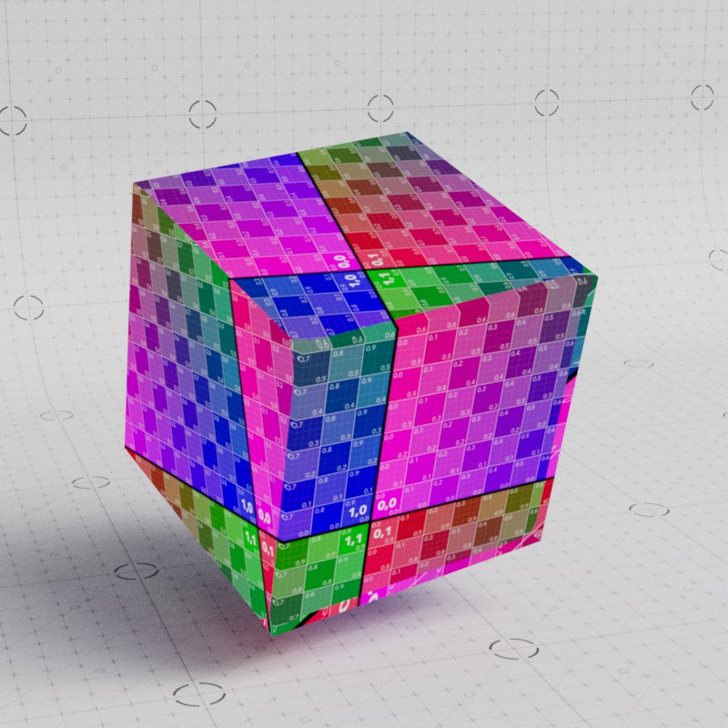
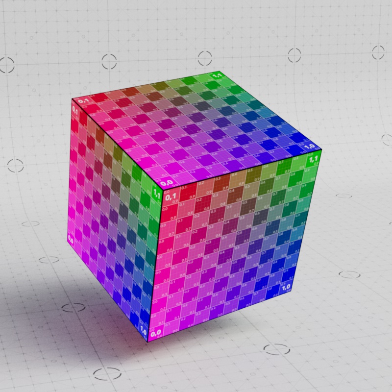
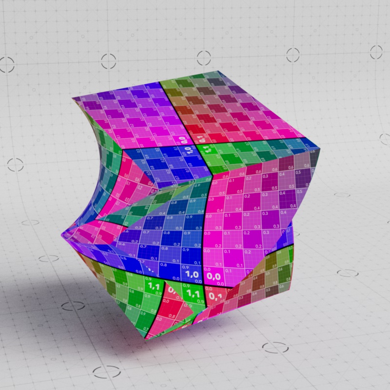
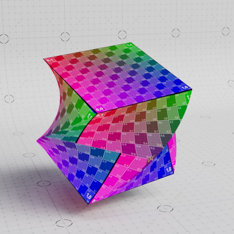
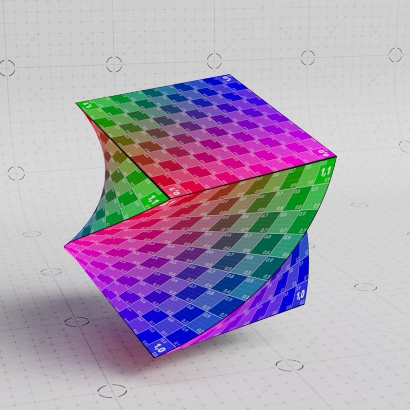
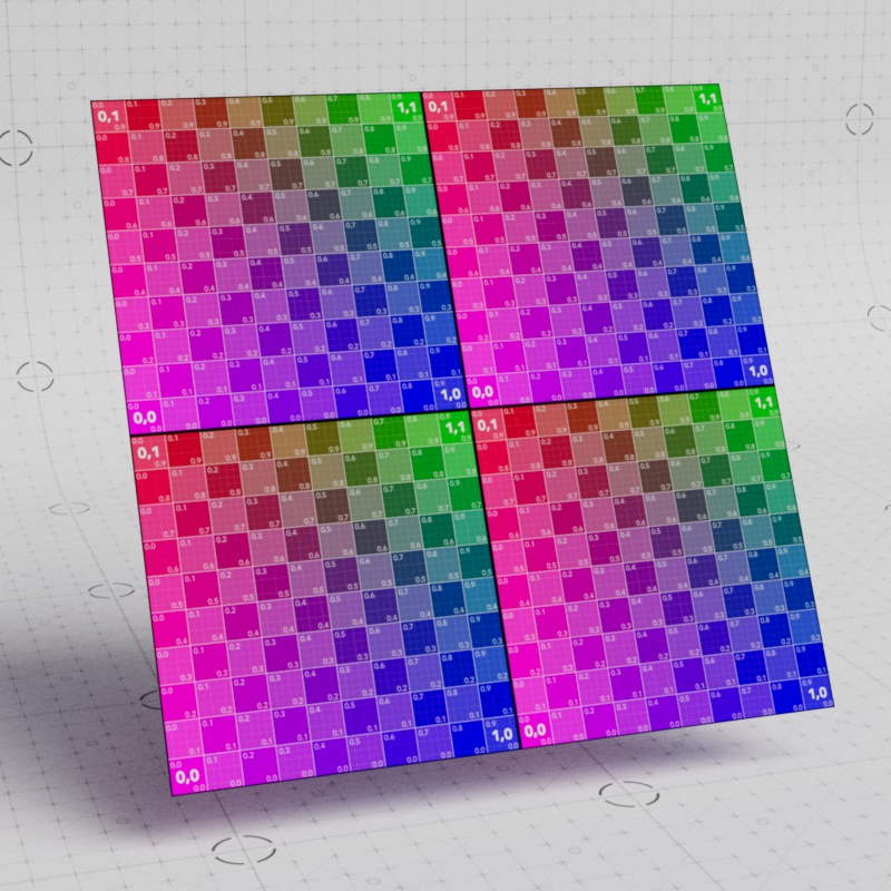
The examples below show how a rotated cube appears with the different projection spaces. The object space options look the same and stick to the object, while the world space option does not.
|

|
|
| Projection Space: World Undeformed object |
Object | Reference Object |
However, when the object is deformed with a twist Reference Object is the only option where the textures deform with it.
|
|
|
| Projection Space: World Deformed object |
Object | Reference Object |
Coordinates
Transform Source
Controls where the projection gets its transform coordinates:
- Shader: The coordinates are controlled by the transform parameters below.
- Object: The coordinates are referenced from an object in the scene. Allowing you to control the projection position, rotation, and scale by transforming the object specified by the Object Picker below.
- The Projection Size is still controlled by the Size X, Y, Z parameters but the result is multiplied by the scale of the picked object. Keep the object at a scale of 1,1,1 to retain physically accurate sizing.
Object Picker
Only available when the Transform Source is set to Object.
Controls which object is referenced for the projection's transform coordinates.
A picked object's transform scale acts as a multiplier on the projection size, so make sure the scale of the object is 1,1,1 if you want the size to remain physically accurate.
When using the Camera projection mode, the camera you want the textures to be projected from should be set here.
In the examples below, a flat projection is used to project a "Cool" texture on the brick wall and the floating gizmo is used as the object picker to define its transform coordinates in World space.
| Moving a projection with an object | Rotating a projection with an object | Scaling a projection with an object |
Film Aspect
Only available when the Projection type is set to Camera
Sets the aspect ratio of width to height of the projected texture. The value used to represent the aspect ratio is the result of the width divided by the height. For example a 16:9 image is equivalent to 1.7778:1
| Film Aspect: 0.5 to 1.5 |
Pixel Aspect
Only available when the Projection type is set to Camera
If the texture does not use a standard pixel ratio of 1:1, a different pixel aspect ratio can be set here.
Physical Size
Not available with World space projection because the size is already calculated irrespective of the object's scale.
When enabled, the scale of the object the material is applied to is not factored into the projection's size. This is helpful when accurate sizing of the texture is most important, allowing you to rescale the object without affecting the texture size. Note, the textures swim when the object is scaled in order to retain the physical size.
When disabled, the scale of the object the material is applied to is multiplied with the projection size. This keeps the texture from swimming but the texture is stretched when the object is scaled, meaning the physically accurate sizing is lost when at a scale other than 1,1,1.
| Physical Size: Enabled | Disabled |
Uniform Size
When enabled, the projection is uniformly sized, with all three axes using the Size X value. When disabled, the size can be set per axis.
| Uniform Size: Enabled | Disabled |
Size X
Sets the size of the projection along the X axis.
The cube in the examples below is 10 x 10 x 10 units.
| Size X: 1 - 10 |
Size Y
Sets the size of the projection along the Y axis.
| Size Y: 1 - 10 |
Size Z
Not available with Flat projection
Sets the size of the projection along the Z axis.
| Size Z: 1 - 10 |
Position
Controls the position of the projection.
| Animating the projection Position |
Rotation
Controls the rotation of the projection.
| Animating the projection Rotation |
Tri-planar
Axis Rotate
Rotates the projected texture on each axis. This is distinct from the Coordinate rotation which rotates the entire projection.
| Animating the Tri-planar Axis Rotate |
Axis Blend
Controls how much the tri-planar projection can overlap and blend in areas that transition from one axis to another. A high value results in a soft transition while a value of 0 results in a hard border between axes.
The Axis Blend effect does not work with Displacement. You can use it with a material that has displacement but the displacement renders as if the Axis Blend is set to 0.
| Axis Blend: 0 - 1 Blend Noise: 0 |
0 - 1 5 |
Blend Curve
Axis Blend must be greater than 0 for this to have an effect.
Controls the power curve of the axis blend transition. Higher values tighten the blend while lower values soften it. A value of 1 results in a linear blend.
| Blend Curve: 1 - 10 |
Blend Noise
Distorts the tri-planar axis border with a noise. Adding noise can provide a more organic texture mapping than the rigid tri-planar projection by default. Higher values add more distortion to the border while a value of 0 disables the effect.
| Blend Noise: 0 - 10 |
Noise Scale
Controls the scale of the tri-planar border noise. Higher values result in a noise with larger shapes while lower values result in a noise with smaller shapes.
| Noise Scale: 1 - 20 |
UV Transform
Tiling
Sets the UV Tiling Mode between the following options:
- Square: Traditional square tiling. Offers standard repeat, flip, and clipping behavior for texture tiling.
- Hex: Obscures texture repetition using a hexagonal shapes to add random variation across a large area. Great for covering large areas and surface imperfection maps.
Hex Tiling limitations
Does not affect procedural textures like Maxon Noise. These can be used and layered with Hex Tiling, but procedural textures will not take part in any of the hex randomization.
Does not work with Texture Displacement's "Smart Bake" feature. The advantage of randomizing and eliminating texture repetition is unfortunately not compatible with the most efficient form of tiling. However, Auto Bump can be used to fill in some of the detail for a small sacrifice in quality.
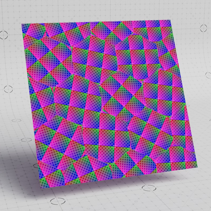
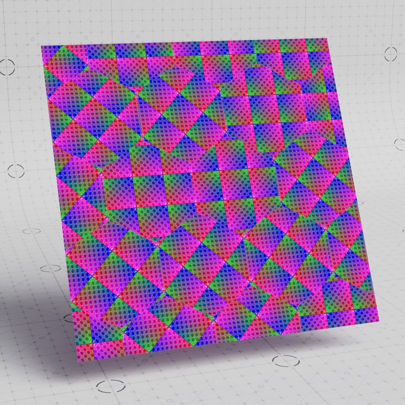
|
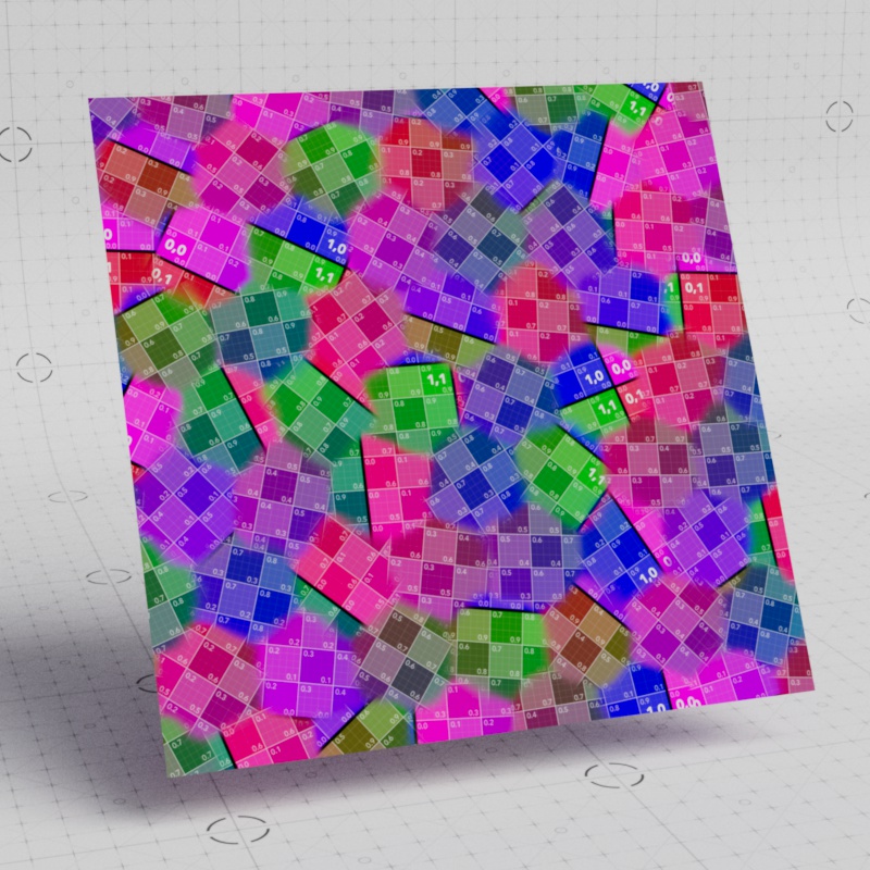
|
| Tiling: Square |
Hex |
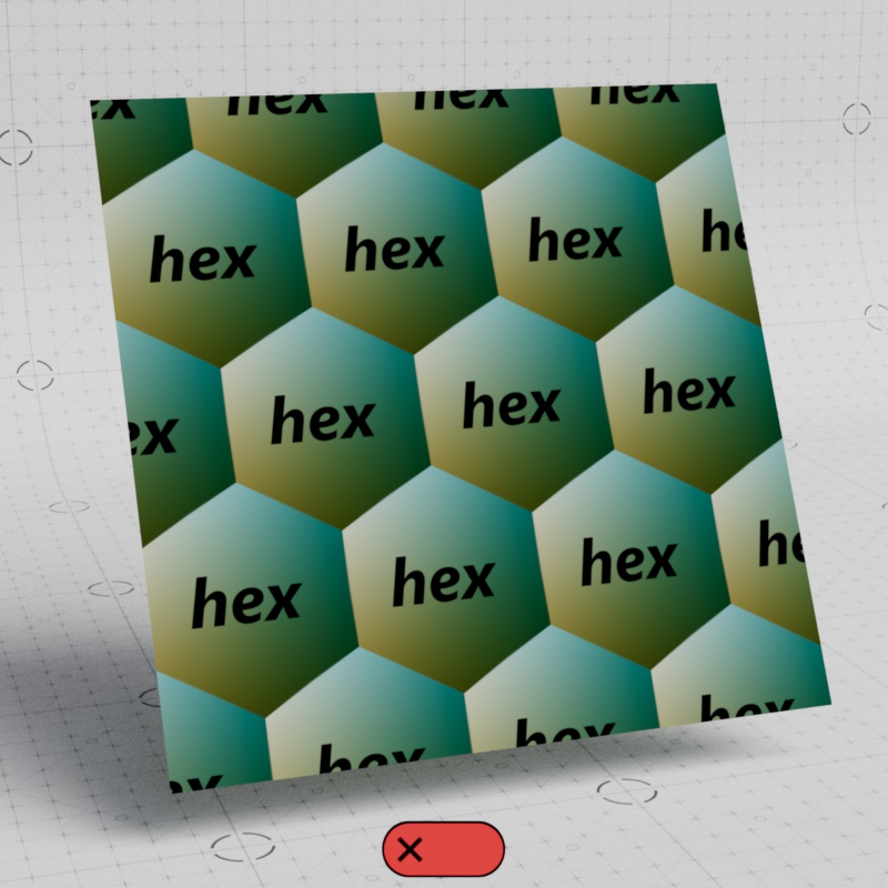
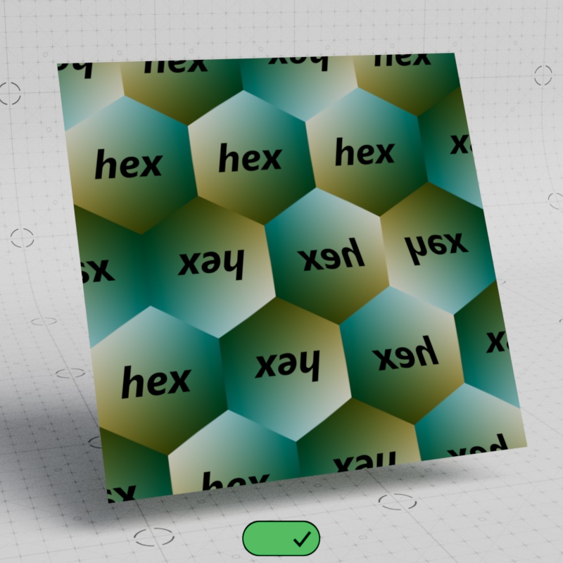
|
|
| Tiling: Square | Hex |
Uniform Tiles
When enabled, the texture is uniformly tiled using the Tiles U value, making it easy to adjust basic tiling patterns. When disabled, the tiling can be set per axis.
| Uniform Tiles: Enabled | Disabled |
Tiles U
Controls how many times the texture is tiled in the U axis (horizontal).
Tiling via the UV Context Projection allows for much more efficient baking when used with Texture Displacement's "Smart Bake" feature. For more information, please see the Tessellation and Displacement page.
| Tiles U: 0 - 3 Uniform Tiles: Disabled |
Tiles V
Controls how many times the texture is tiled in the V axis (vertical).
| Tiles V: 0 - 3 Uniform Tiles: Disabled |
Offset
Moves the texture.
| Animating the offset | Animating the offset with a PBR material |
Rotate
Rotates the texture. Note, the Pivot affects the center point of that rotation.
| Animating the UV Transform Rotate |
Pivot
Moves the texture's pivot point which affects how a texture is rotated. Note, changing the number of tiles affects the visual center point of the pivot. By default the pivot is centered in the middle of a single tile at 0.5, 0.5. If the texture is tiled twice and you still wanted the pivot point visually centered then you'd want to set it to 1,1, placing it at the center of the four tiles. A value of 0,0 places the pivot point at the bottom left of the UV space.
In the first example the pivot point is centered, note how the pivot is half of the number of tiles in order to fall in the center.
| Pivot: 0.5, 0.5 Tiles: 1 x 1 |
1, 1 2 x 2 |
Here the first example has the pivot point anchored in the bottom left in UV space with a value of 0, 0. While the second value has it anchored in the upper right, with a value of 1, 1.
| Pivot: 0, 0 Tiles: 1 x 1 |
1, 1 1 x 1 |
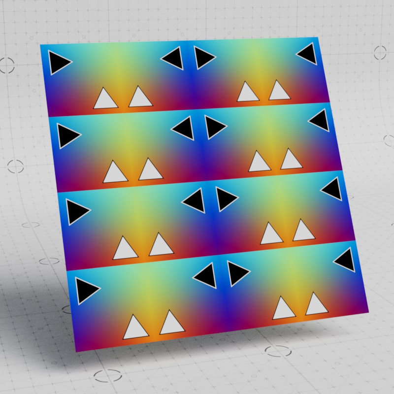
Wrap U
Square Tiling only
Controls how the texture is tiled along the U axis (horizontal) with the following options:
- Repeat: The texture is repeated. (default)
- Mirror: The texture is mirrored every other tile. Mirror is not compatible with Texture Displacement's "Smart Bake" feature.
- Clip: The texture is displayed once and if the texture moves out of the 0-1 range the Default/Invalid Color of the texture is rendered.
|
|
|
| Wrap U: Repeat | Mirror | Clip |
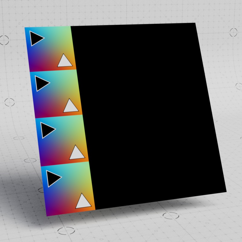
Wrap V
Square Tiling only
Controls how the texture is tiled along the V axis (vertical) with the following options:
- Repeat: The texture is repeated. (default)
- Mirror: The texture is mirrored every other tile. Mirror is not compatible with Texture Displacement's "Smart Bake" feature.
- Clip: The texture is displayed once and if the texture moves out of the 0-1 range the Default/Invalid Color of the texture is rendered.

|

|

|
| Wrap V: Repeat | Mirror | Clip |
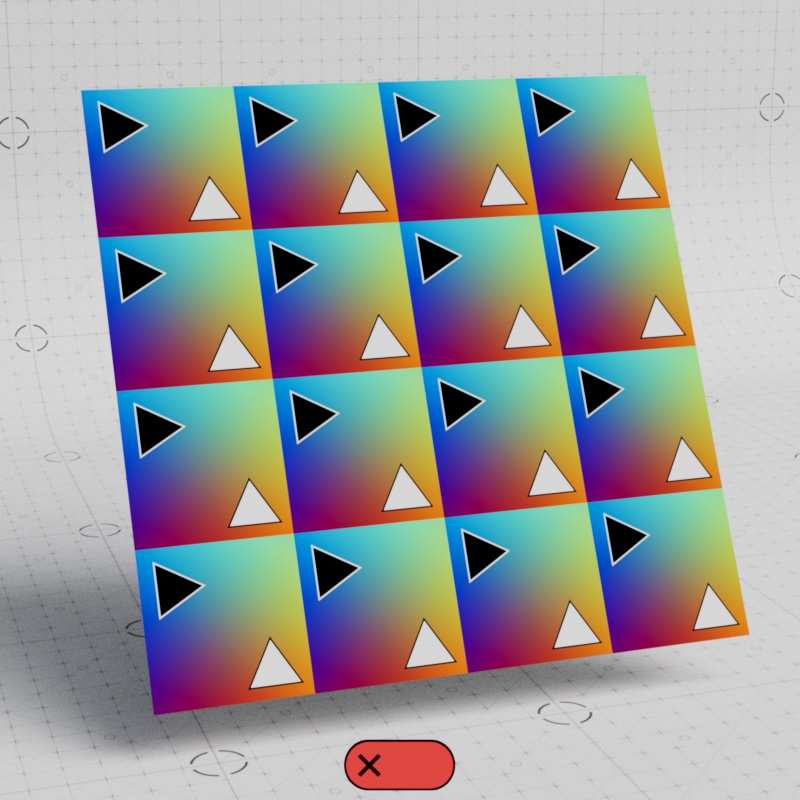
Flip U
Square Tiling only
When enabled, the texture is flipped along the U axis (horizontal).
|
|
| Flip U: Disabled | Enabled |
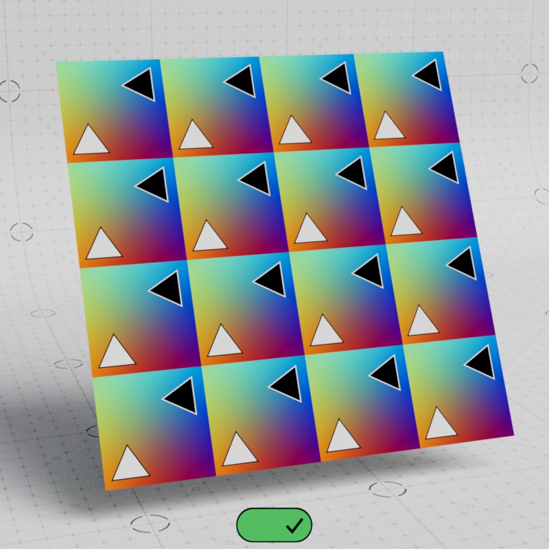
Flip V
Square Tiling only
When enabled, the texture is flipped along the V axis (vertical).

|

|
| Flip V: Disabled | Enabled |
Tile Blend
Hex Tiling only
Controls how much blending occurs between hex tiles. Higher values result in more blending.
| Hex Tile Blend: 0 - 1 |
Blend Curve
Hex Tiling only
Controls the power curve of the hex tile blend. Higher values tighten the blend while lower values soften it. A value of 0.5 results in a linear blend.
| Hex Tile Blend Curve: 0 - 1 |
Blend Noise
Hex Tiling only
Distorts the hex tile borders with a noise. Adding noise helps break up repetition that can be revealed in the hex tile pattern itself. Higher values add more distortion to the border while a value of 0 disables the effect.
| Hex Tile Blend Noise: 0 - 1 |
Noise Scale
Hex Tiling only
Controls the scale of the hex tile border noise. Higher values result in a noise with larger shapes while lower values result in a noise with smaller shapes.
A large noise tends to work well with textures with large broad features while a smaller noise might work better with a texture that has lots of fine detail.
| Hex Tile Noise Scale: 0.05 - 0.5 |
Random Seed
Hex Tiling only
Changes the seed used to drive hex tiling randomization.
| Changing the Hex Tile Random Seed |
Random Offset
Hex Tiling only
Controls how far the texture can be randomly offset in the X and Y direction from its starting position inside each hex tile.
Higher values move the texture more inside each hex tile, the hex tile repeats automatically so it can never be pushed outside of range. A value of 0 results in no offset where all textures are centered within each hex tile.
| Random Offset: 0 - 1 |
Random Rotate
Hex Tiling only
Controls how far the texture can be randomly rotated inside each hex tile in degrees.
Note, the rotation value works both clockwise and counter clockwise. Meaning a value of 20 gives it a maximum rotation range of 40°.
| Random Rotate: 0 - 45 Rotate Mode: Range |
Rotate Mode
Hex Tiling only
Controls how the Random Rotate parameter works from the following options:
- Range: (default) The textures inside each hex tile are rotated smoothly from 0 up to the maximum rotation range.
- For example, a Random Rotate of 5 results in random float values from -5 to +5 and all the values in between.
- Stepped: The textures inside each hex tile are rotated in increments of the Random Rotation.
- For example, a Random Rotate of 90 results in 0, 90, 180, 270, 360 etc.
Range rotation works great for organic textures that require a truly random look while stepped rotation works well for textures that have an inherent rigidity and orientation.
|
|
| Rotate Mode: Range Random Rotate: 45 |
Stepped 45 |
Scale
Hex Tiling only
Controls the uniform scale of the textures.
Higher values scale the texture up while lower values scale the texture down. A scale of 1 (default) results in the same scale as a texture used in "Square" tiling mode.
| Scale: 0.1 - 2 |
0.5 - 2 |
Random Scale
Hex Tiling only
Controls the random scale of the textures in each hex tile.
Note, this parameter scales textures both up and down. So a value of 1 results in textures that are both smaller and larger while a value of 0 results in no scale change.
| Random Scale: 0 - 1 |
0 - 1 |
Random Flip
Hex Tiling only
Randomly flips the texture in U, V, U+V, directions when enabled for increased variation.
|
|
| Random Flip: Disabled (default) |
Enabled |