Distorter
Overview
The Distorter shader is a utility node that can be used to warp and distort one texture based on another texture. This is accomplished by offsetting the original UV coordinates with values derived from a distortion texture.
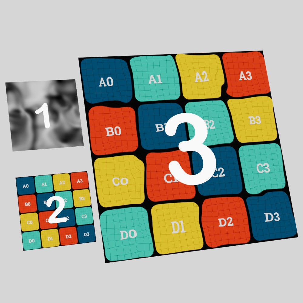
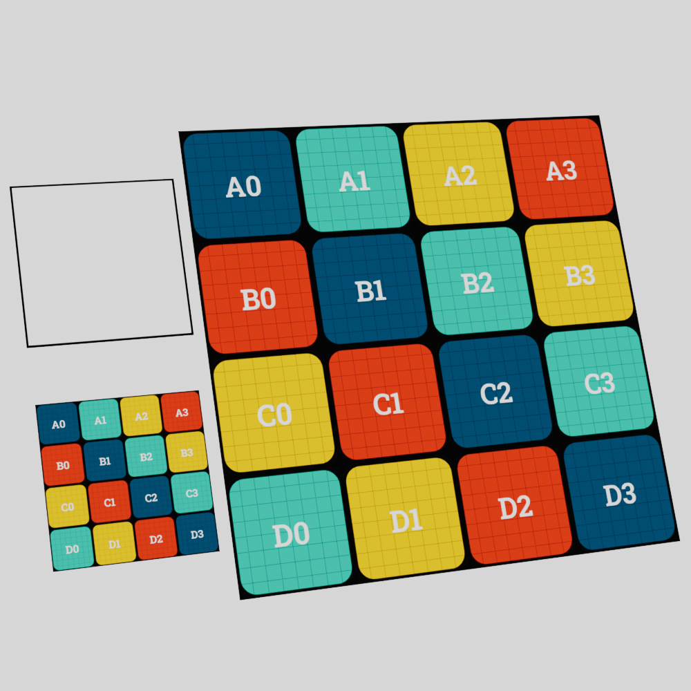
On this page you will see a 3 plane setup for many of the example images, each plane is used to illustrate the following elements:
-
Distorter Texture: This is the texture used to distort the source texture.
-
Source Texture: This is the texture that will be distorted, presented here in its undistorted original form.
-
Result: This is the final result of the source texture distorted by the distorter texture.
|
Examples
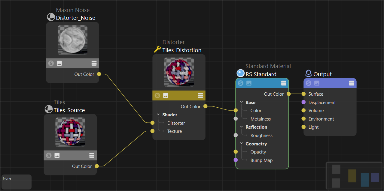
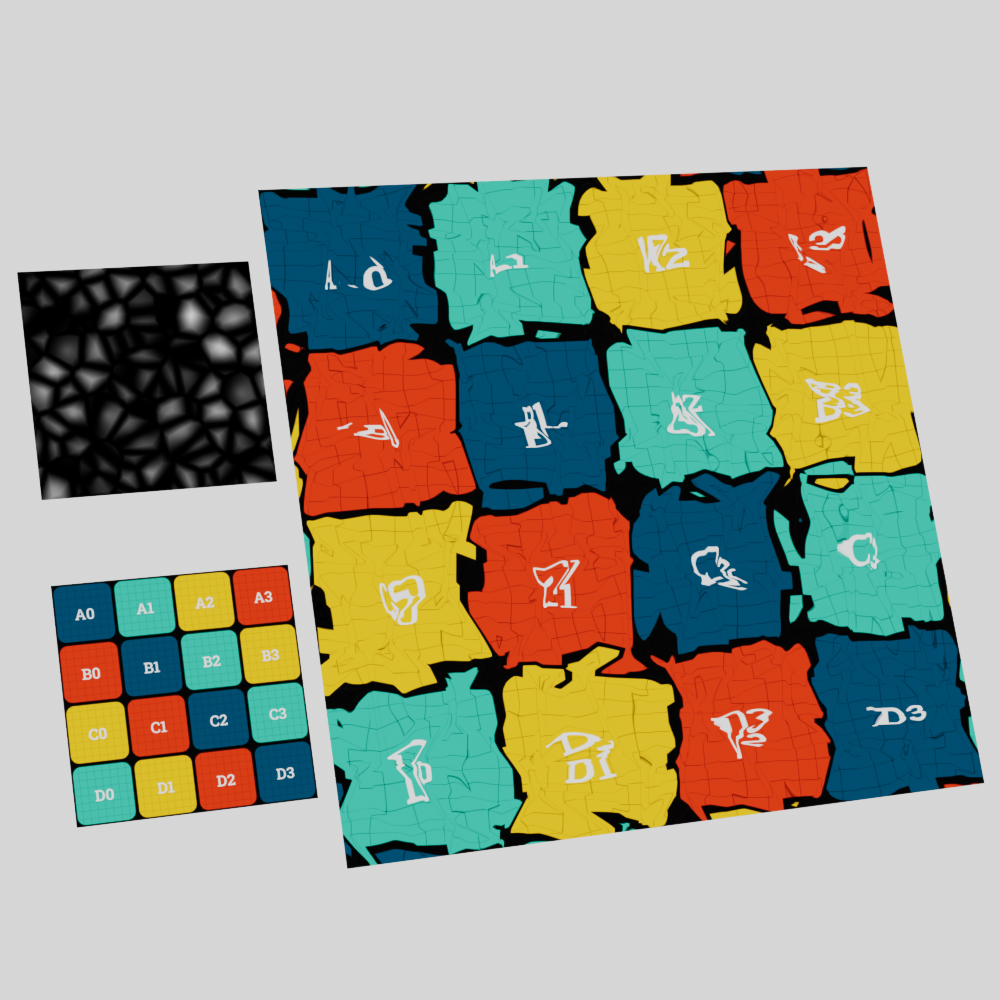
To use a Distorter node start by connecting a source image to the "texture" input as pictured below, this is used as the beauty texture you want to distort. Next connect a texture to the "distorter" input, this is used to drive the intensity of the distortion applied to the source texture. The distorter node itself can then be connected to a color input on a shader. For many of the example images on this page a UV test image was created using the utility at uvchecker.vinzi.xyz.
|
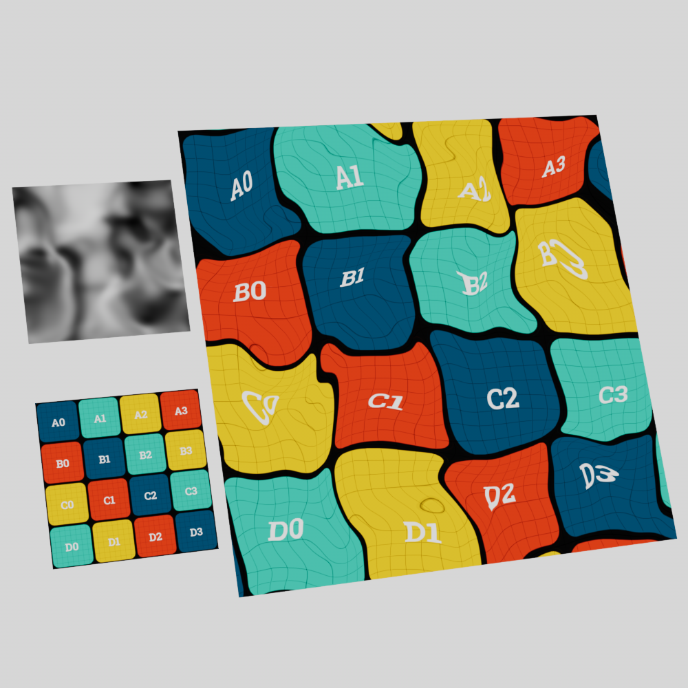
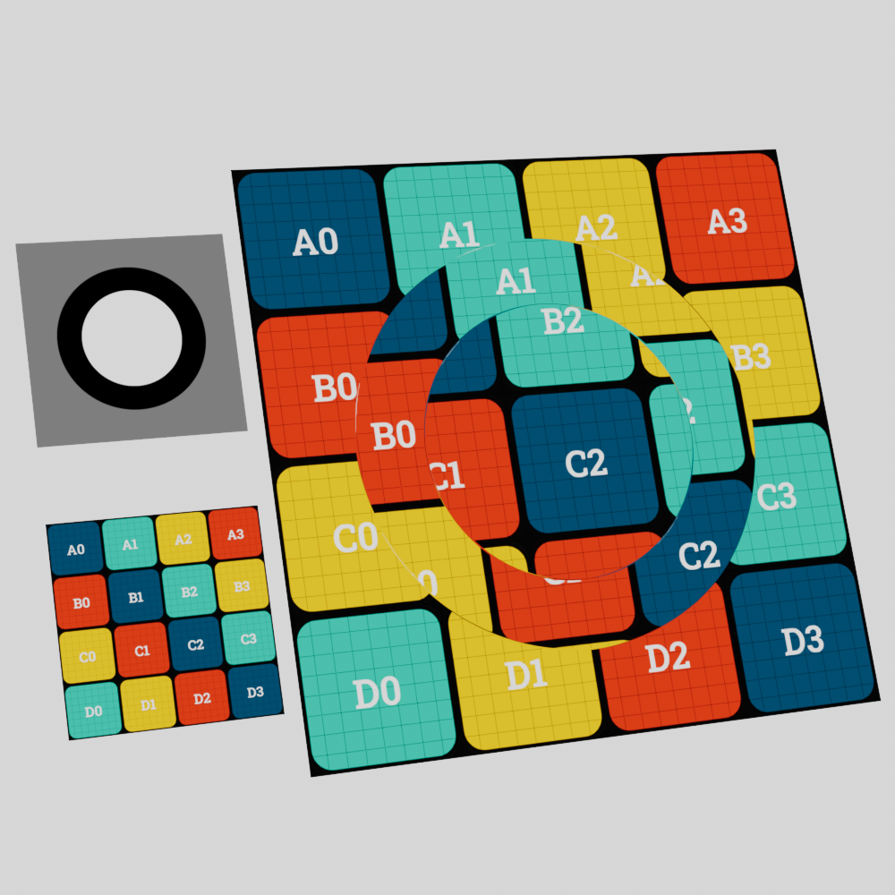
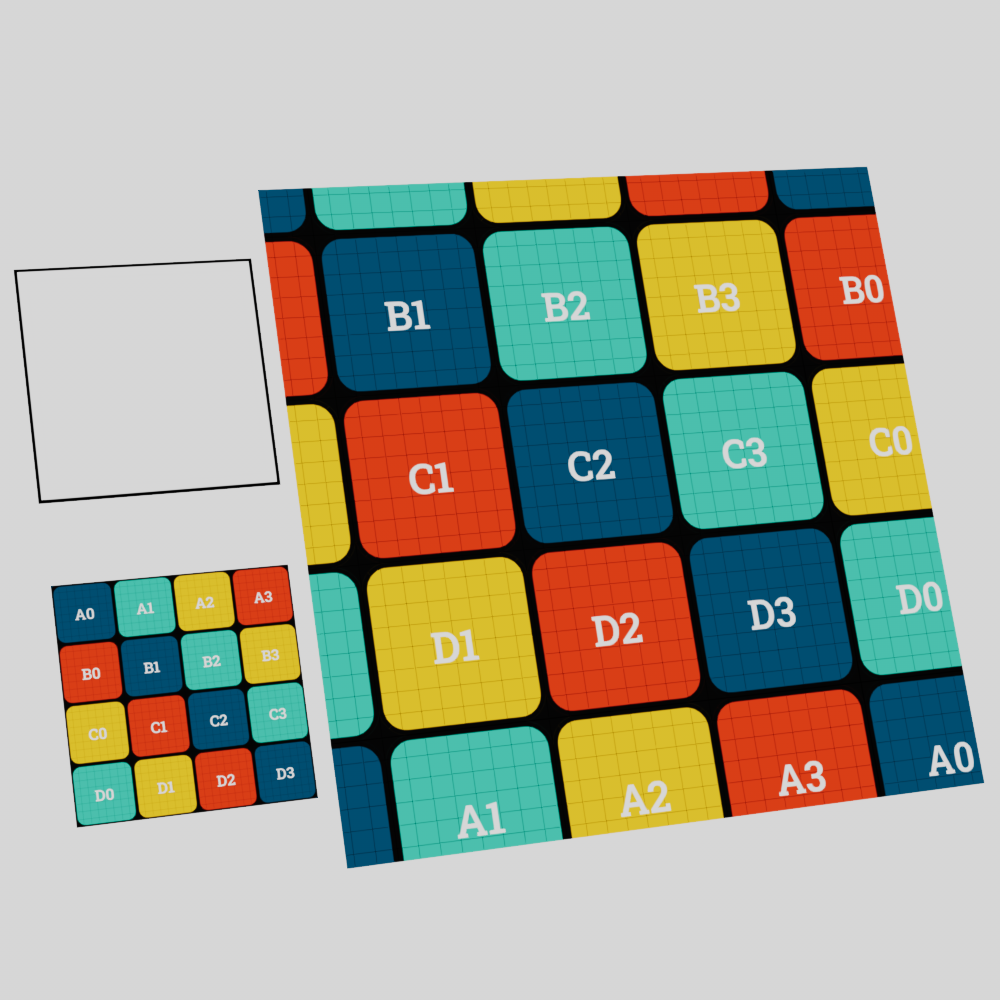
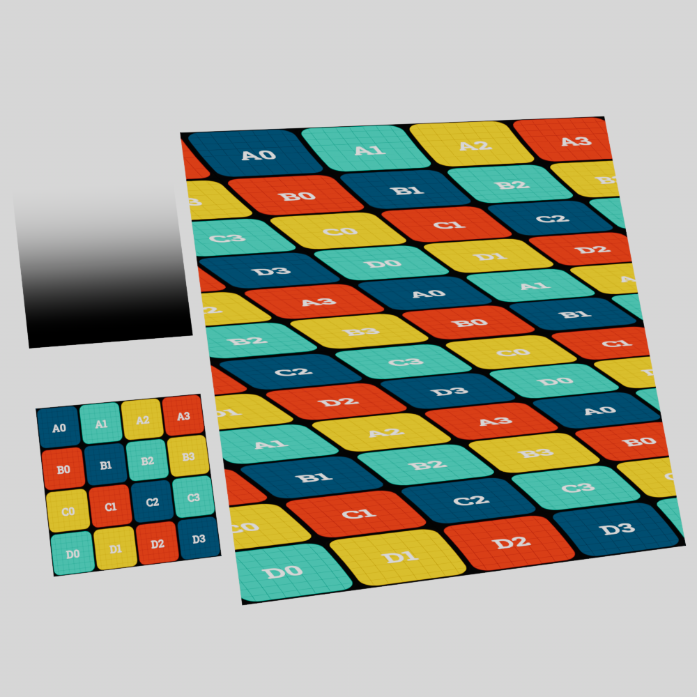
The distortion behavior is dependent on the type of distortion used. The "directional" type works by adding the values found in the distorter texture to the original UV coordinates resulting in an offset texture. Similarly, the "bidirectional" type adds the distorter texture values to the original UV coordinates but then subtracts this sum by 0.5. With both types, higher values result in more distortion while lower values result in less distortion.
|
|
| Type: Directional | Bidirectional |
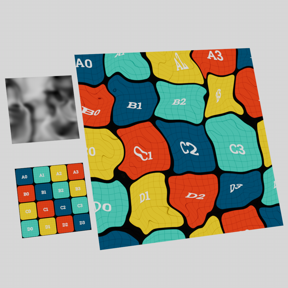
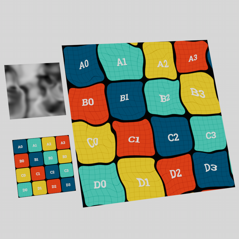
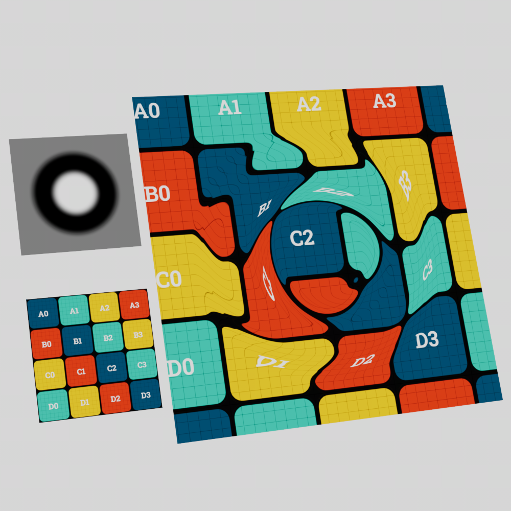
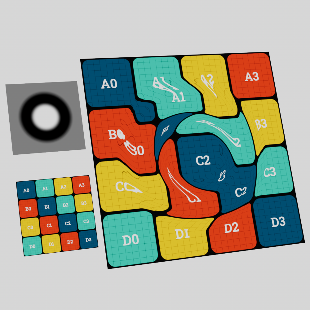
The "flow field" type behaves very differently, instead of higher values simply resulting in more distortion the only time a flow field recognizes distortion is when the values change from one area of the distorter texture to the next. This works by sampling multiple points of the distortion texture in UV space to find the distortion intensity based on the average difference between points. In the example image below note how the distortion of the flow field is entirely concentrated around the transition between each color change, where as the directional and bidirectional types are distorted across the entire area of each colored section. No distortion occurs in the black portion of the directional example (since black = 0) or the grey portion of the bidirectional example (since the 0.5 grey value is perfectly canceled out by the subtraction of 0.5).
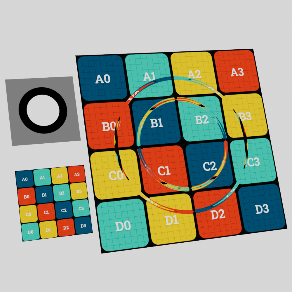
|
|
|
| Type: Flow Field | Directional | Bidirectional |
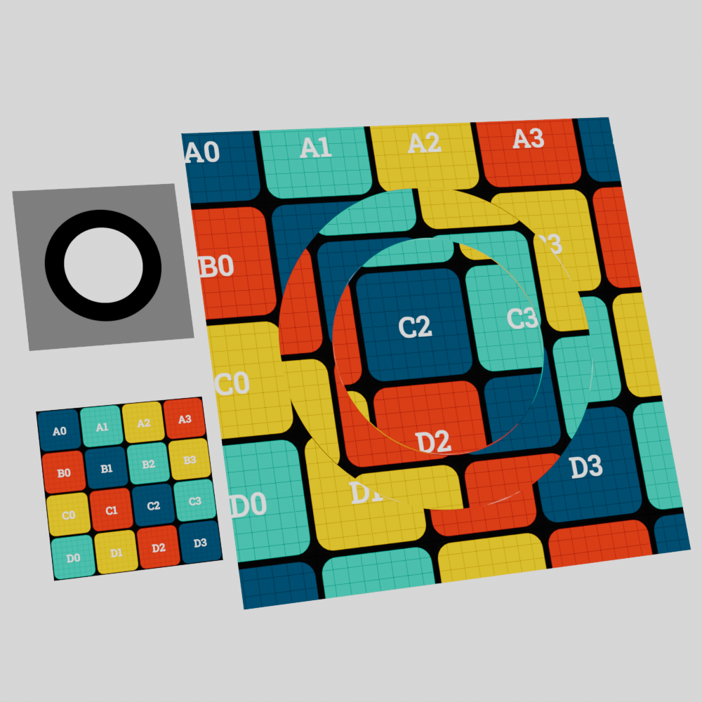
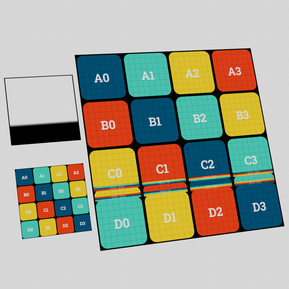
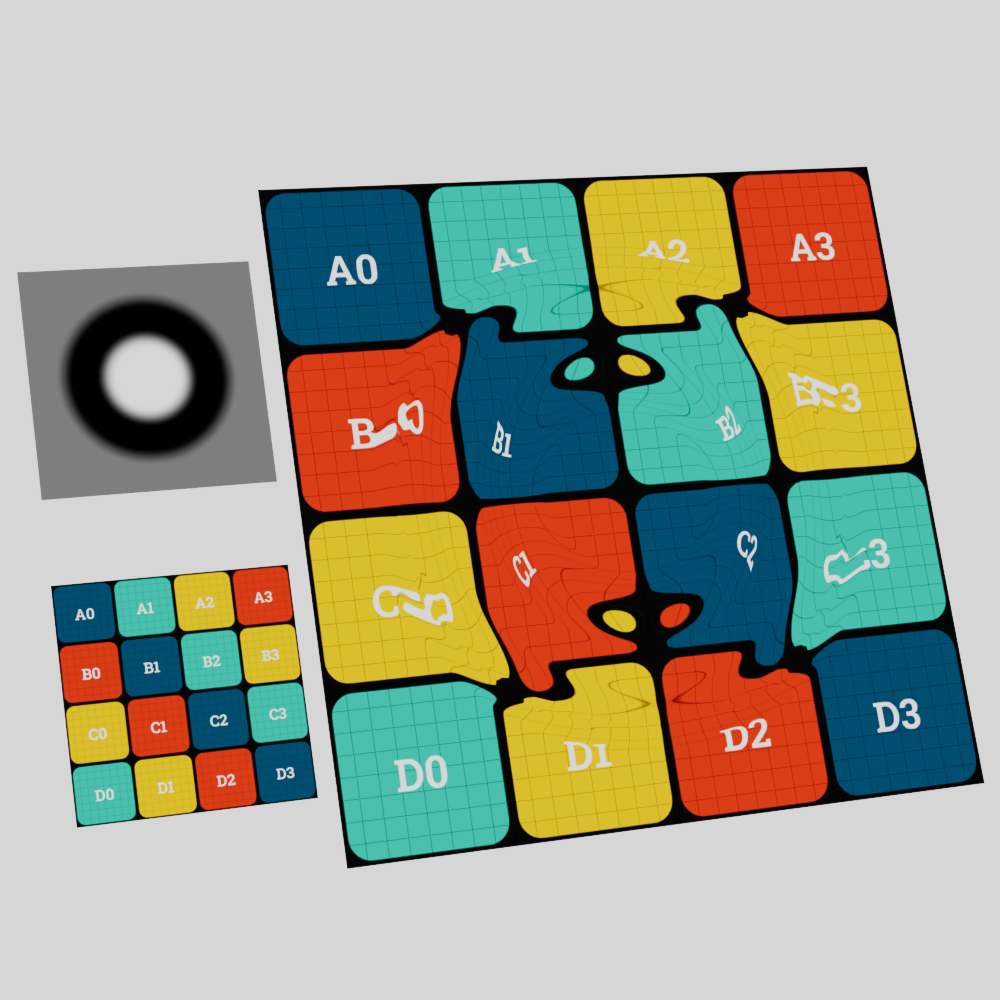
To take this to an extreme, a completely white texture used with the directional and bidirectional types will result in even distortion across the entire texture space but does not result in any distortion when used with a flow field since there is no difference to be found.
|
|
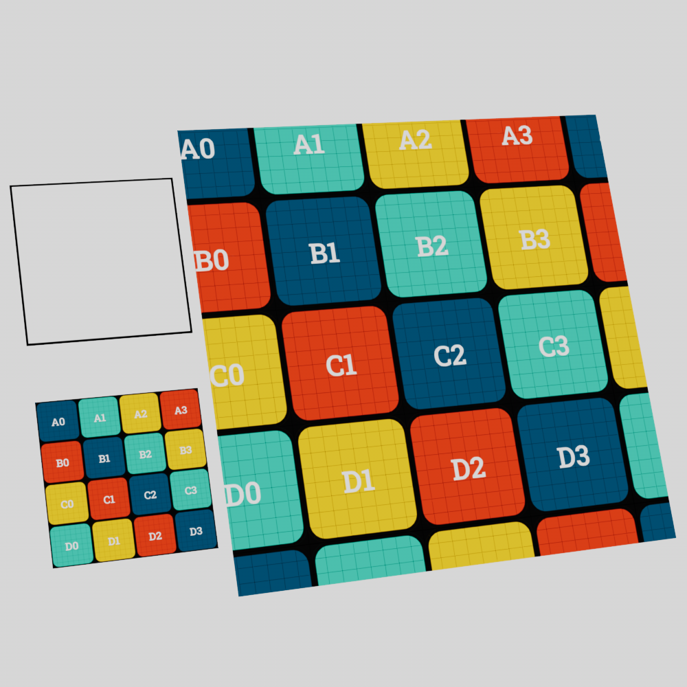
|
| Type: Flow Field | Directional | Bidirectional |
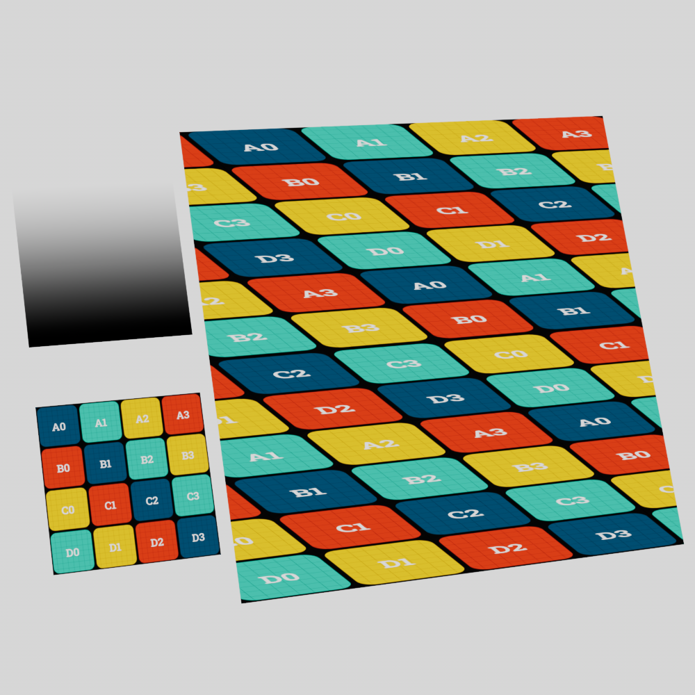
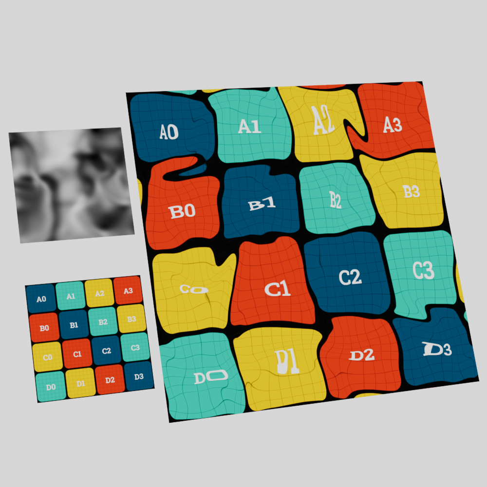
A texture that transitions from black to white results in distortion wherever that transition occurs. The more abrupt the transition the greater the distortion, while a more gradual transition results in less the distortion. In the example images below the same distortion intensity was used for all three examples, the only thing that was changed was how quickly the transition from black to white occurs.
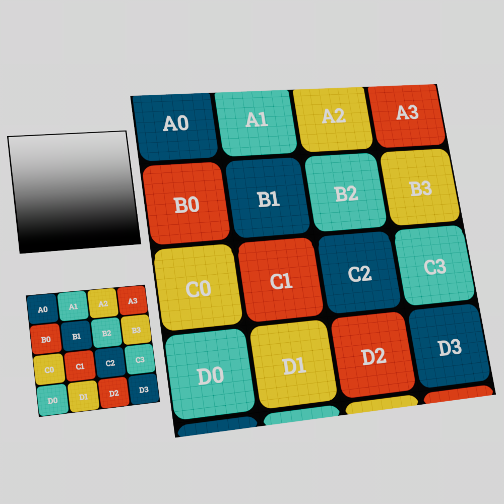
|
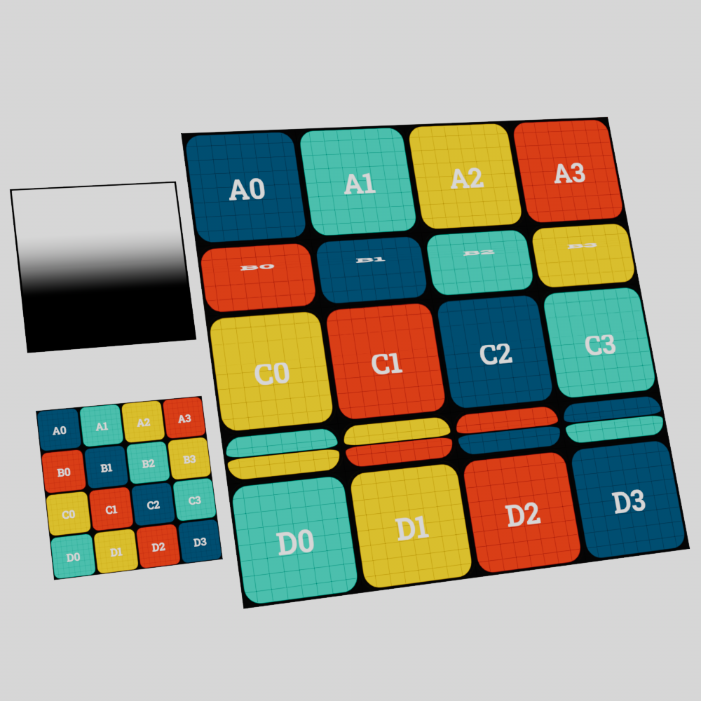
|
|
| Distorter Transition: Gradual Type: Flow Field Distortion Amount: 2 |
Medium | Abrupt |
Parameters
|
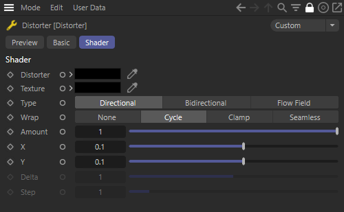
Distorter
The distorter input uses a shader or texture to drive distortion of the source texture. An example of common distorter inputs are noises, color ramps, or other textures.

|
|
|
|
| Distorter: VL Noise | Voronoi 3 Noise | Linear Ramp |
Cubic Ramp |
Texture
The source texture input gets distorted by the distorter, this can be considered the beauty input as the output of a distorter node will be the distorted version of this texture.
|
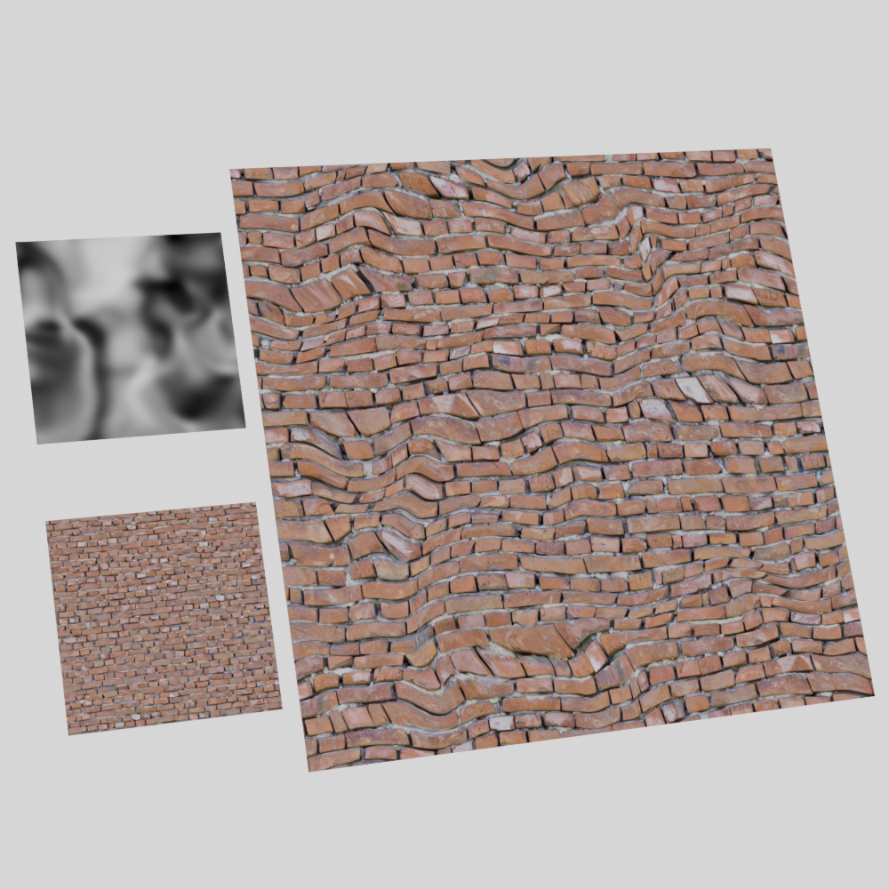
|
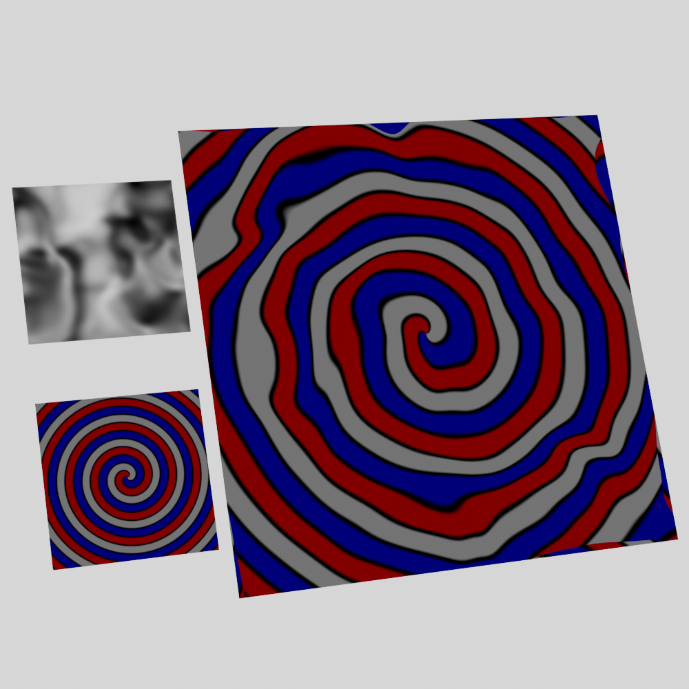
|
| Texture: UV Testing Texture | Brick Texture | Tiles Spiral Texture |
Type
Controls the type of distortion that occurs with the following options:
-
Directional: The value of the distorter input is added to the current UV coordinate. Here black (0) results in no distortion and white (1) results in full distortion. Red and green color channels can be used to control X and Y distortion in isolation.
-
Bidirectional: The value of the distorter input is added to the current UV coordinate and then 0.5 is subtracted. Here black (0) results in negative distortion, grey (0.5) results in no distortion, and white (1) results in positive distortion.
-
Flow Field: Flow Field distortion is based off of the difference in neighboring values found in the distorter input. The distorter input is sampled at multiple points in UV space and the average difference is found between them - larger and more abrupt differences result in more intense distortion while gradual changes result in less distortion. The distance between the sampled points is controlled by the Step parameter.
|
|
|
|
| Type: Directional | ||
|
|
|
|
| Type: Bidirectional | ||
|
|
|
| Type: Flow Field | ||
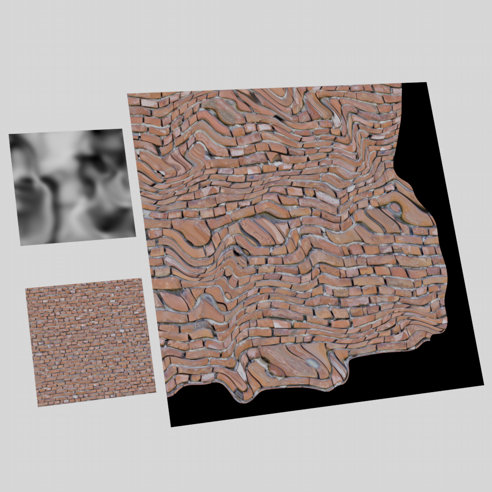
Wrap
Controls what happens when distorted UVs leave the 0-1 range from the following options:
-
None: Uses the texture wrapping method already defined on the source texture itself.
-
Cycle: Overrides the texture wrapping method on the source texture and repeats the texture continuously.
-
Clamp: Overrides the texture wrapping method on the source texture and stretches the texture indefinitely based on the delta value.
-
Seamless: Overrides the texture wrapping method on the source texture and repeats the texture by continually mirroring the texture.
| Distorter Wrap: None Source Texture Wrap: Disabled Distortion Amount: 0 to 3 |
Cycle | Clamp | Seamless |
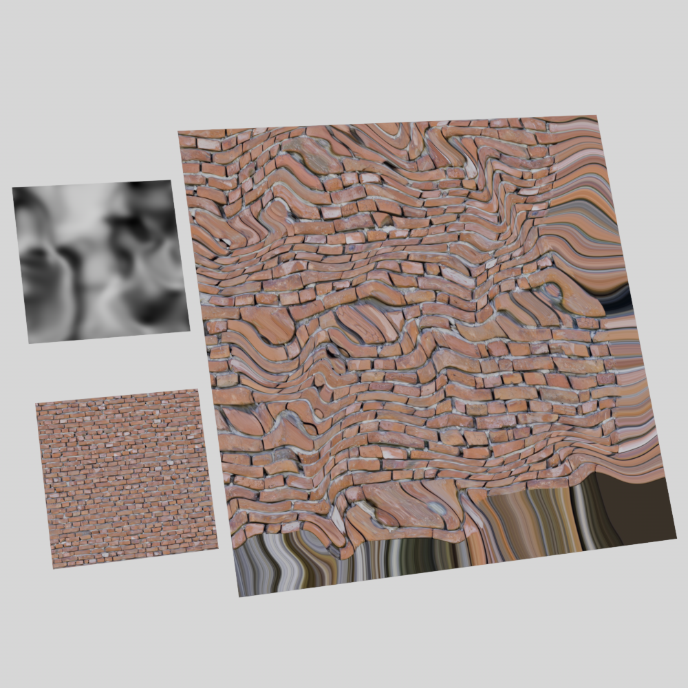
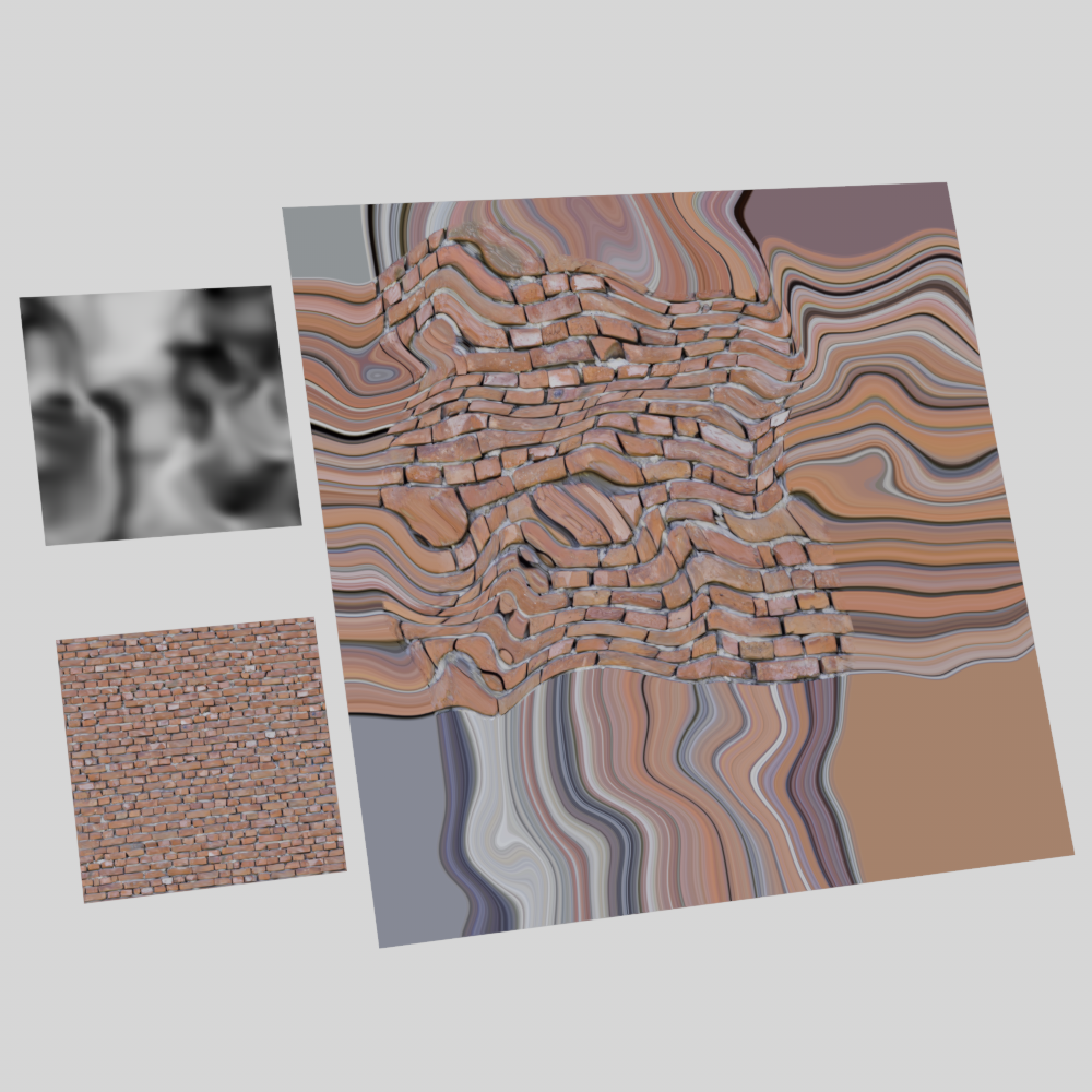
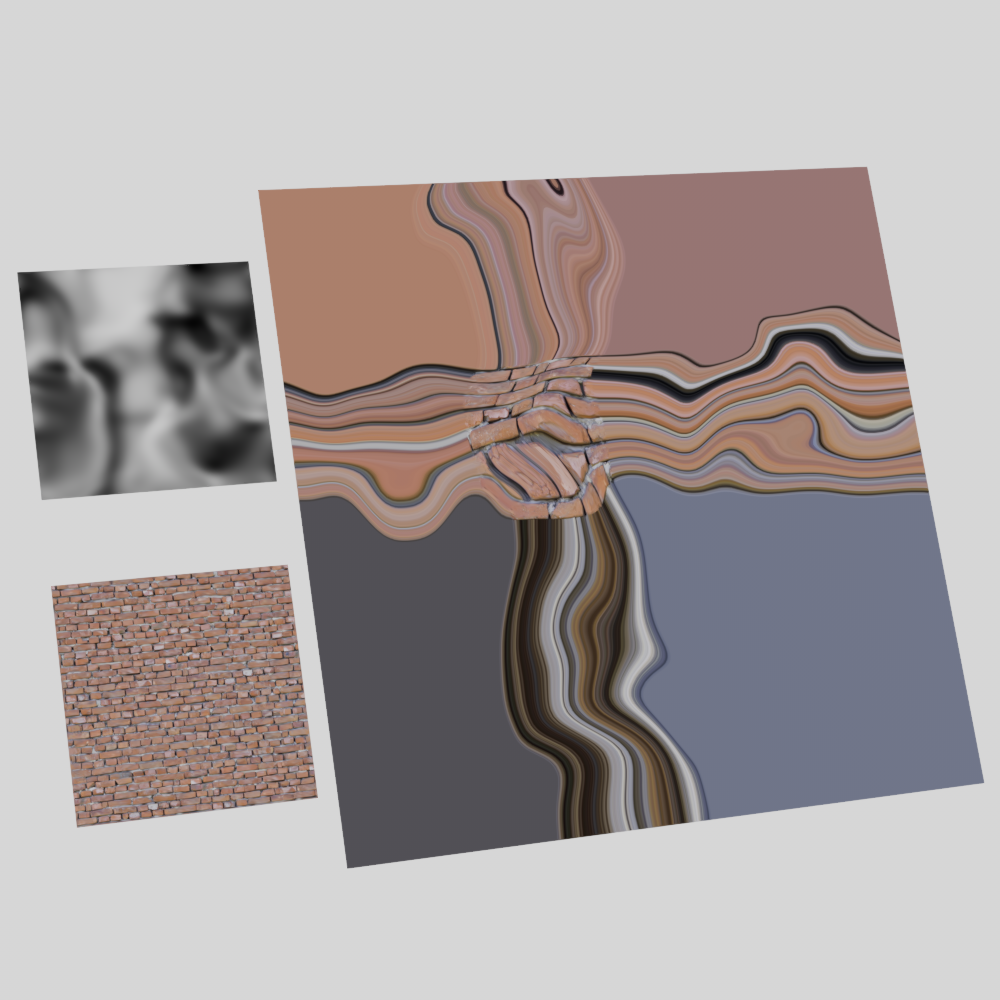
Amount
Scales the overall intensity of the distortion.
| Amount: -2 to 2 Distortion Type: Directional |
Bidirectional |
Flow Field |
X
Scales the intensity of the distortion in the U direction. For directional distortion the red channel can be used to control X distortion in isolation.
| X Intensity: -2 to 2 Y & Z Intensity: 0 Distortion Type: Directional |
Bidirectional |
Flow Field |
Directional |
Y
Scales the intensity of the distortion in the V direction. For directional distortion the green channel can be used to control Y distortion in isolation.
| Y Intensity: -2 to 2 X & Z Intensity: 0 Distortion Type: Directional |
Bidirectional |
Flow Field |
Directional |
Z
Z distortion requires a 3D source texture, like a Maxon noise in world or object space. Z distortion does not work when the source texture only operates in 2D space with UV coordinates as seen in the example image below.
Scales the intensity of the distortion in the Z direction. For directional distortion the blue channel can be used to control Z distortion in isolation.
| Z Intensity: -2 to 2 X & Y Intensity: 0 Distortion Type: Directional |
Bidirectional |
Flow Field |
Directional |
Directional |
When using a 3D source texture the distortion direction is dependent on the orientation of the object in the scene.
| X Intensity: -2 to 2 Y Intensity: 0 Z Intensity: 0 Distortion Type: Directional |
X Intensity: 0 Y Intensity: -2 to 2 Z Intensity: 0 |
X Intensity: 0 Y Intensity: 0 Z Intensity: -2 to 2 |
Delta
Only compatible with Clamp wrap type.
Controls how the texture clamping is handled when the texture leaves the 0-1 UV range. Higher values increase the clamping inset on the texture while lower values decrease the inset.
|
|
|
|
| Delta: 1 Clamp: Wrap |
5 | 7 | N / A None |
Step
Only compatible with Flow Field distortion type.
Controls the step size for the sampled points which is used for evaluating the flow direction and intensity. Higher step values increase the distance between each point which tends to increase the likelihood for more intense distortion, while very low values result in little to no distortion. When used with a 2D source texture points are sampled along UV coordinates. When used with a 3D source texture points are sampled along the tangent/bitangent direction.
| Step: 0-3 Amount: 5 |