SSS (Subsurface Scattering)
This shader is deprecated! Please use the Standard Material instead, it has greatly improved subsurface scattering capabilities.
Introduction
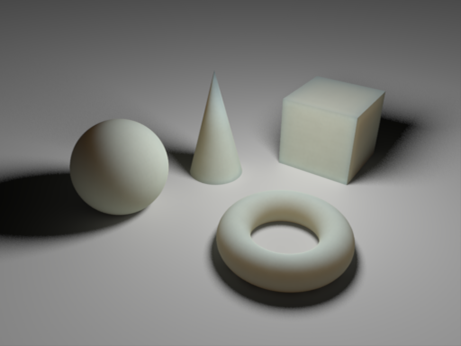
When light hits certain types of translucent surfaces, it enters the medium, gets scattered within it and then a percentage of it exits it. The result is the familiar soft lighting effect of materials such as wax, milk, thin plastic or human skin. That lighting effect is called "Subsurface Scattering", here abbreviated as "SSS".
Subsurface Scattering
Redshift supports a fast point-based SSS implementation through the "Redshift Subsurface Scattering" shader node. Just like other point-based techniques (such as Irradiance Caching), part of the computation happens in a separate pass and the points are used for shading during the final rendering pass.

Because subsurface scattering can be a multi-pass technique, apart from the shader parameters, it also has a few global options. These are explained below.
Global Options
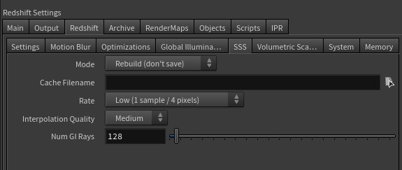
Mode/Filename
- When "Mode" is set to "Rebuild (don't save)", Redshift will compute new subsurface scattering points from scratch (for each frame) but will not save them to disk.
- When "Mode" is set to "Rebuild (prepass only)", Redshift will compute new subsurface scattering points from scratch (for each frame) and will save them to the user-specified file. The final rendering pass will be skipped.
- When "Mode" is set to "Rebuild", Redshift will compute new subsurface scattering points from scratch (for each frame) and will save them to the user-specified file.
- When "Mode" is set to "Load", the computation stage is skipped and the data is loaded from the user-specified file.
Subsurface scattering data is view-dependant which means that it has to be re-generated when either the camera or any objects move. It also has to be regenerated if lights change (position or intensity) and if materials are adjusted. However, there are a few settings that do not affect the subsurface scattering points:
- All antialiasing settings
- Any parameter that has to do with "number of samples". For example "number of glossy rays", "number of area light samples", "depth of field num samples"
If you are making any last-minute adjustments to your frame and tweaking these kinds of parameters you can save some time by re-using the irradiance cache you computed last time.
Rate
This parameter controls the spacing of the SSS points. Similar to antialiasing, the more samples-per-pixel you use the more points will be created. More points can help catch small details but they also take longer to compute and occupy more memory. It is recommended that, if you get visual artifacts, you try a setting of "Medium (1 sample per pixel)" first and then raise it to "High (4 samples per pixel)".
Interpolation Quality
During the final rendering stage, the SSS points are used to produce the final lighting at each pixel. This parameter controls the quality of this process. The higher the setting, the more points are used and the smaller the chance of any interpolation artifacts appearing on the surfaces of objects. Higher settings, though, also mean longer rendering. We recommend leaving this setting to its default "Low" value and only use "Medium" or "High" if you observe SSS artifacts that look like 'lighting rings' or excessive flickering in animations.
Num GI Rays
If Global Illumination is enabled, GI lighting will also be computed for each SSS point. This means that and bounced lighting will also be scattered through any objects using a subsurface scattering shader. The "Num GI Rays" is similar to the Brute-Force GI or Irradiance Cache GI "num rays" settings.
Since subsurface scattering is a soft effect, it can often work with relatively few GI rays whereas GI on hard surfaces might require several hundred (or even thousands) rays. It is, therefore, recommended that you start with fairly low numbers such as the default 128 and raise this only if you get persistent lighting artifacts on subsurface scattering surfaces.
SSS Shader General Parameters
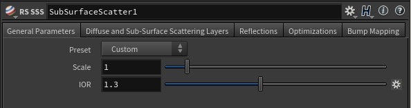
Preset
The "Preset" list contains settings for a few different types of materials. You might have seen the same list on other renderers. These settings originate from the original subsurface scattering paper "A Practical Model For Subsurface Light Transport" by Henrik Wann Jensen. The SSS implementation of Redshift is based on that work.
If you are new to subsurface scattering, it is recommended that you use the preset list as a starting point as it can help you understand the effect of the "sub-surface color" and "scatter color" parameters.
Scale
The scale controls how soft or hard the SSS effect will be. Higher numbers make the effect softer. This value is multiplied by the "Scatter Radius" parameter explained below.
IOR
The index of refraction used to calculate the strength of the Fresnel effect. Often, the IOR of water (which is approximately 1.3) is sufficient for most subsurface scattering effects.
Diffuse and Sub-Surface Scattering Layers
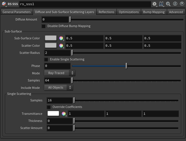
Diffuse Amount
This parameter controls how much of the SSS effect you get. A value of 0.0 means that you'll only get subsurface scattering. On the other hand, a value of 1.0 will make this surface behave as a perfectly diffuse surface without any SSS. This parameter is useful for materials that need a weaker SSS effect.
Sub-Surface
Mode
- Point-Based
- Ray-Traced
You can use either point-based or ray-traced multiple sub-surface scattering in Redshift and both have their own advantages and disadvantages. In quite a few cases the techniques should look similar to each other but there are situations where the differences will be readily apparent, this is primarily due to the normalization of light that occurs when using point-based mode. Ray-traced mode does not normalize the light which can lead to differences that are most notable on thin objects or objects with more surface detail.
If your scene is setup to use point-based SSS shaders and you render in progressive mode it will automatically use ray-traced SSS during progressive renders. This way you can actually see the SSS effect in progressive mode (and not just the diffuse texture) and tweak settings interactively - while still using point-based for the final (bucket) rendering.
Please note that due to the differences in the two modes that the final result can differ when comparing progressive ray-traced SSS to the bucket rendered point-based SSS.
Point-Based
-
Faster and smoother
-
Less detailed / accurate
-
Does not work in progressive mode
-
Requires a "prepass" stage
-
Higher chance of flickering in difficult lighting situations.
-
Not possible to isolate SSS effect on a particular object which can result in unnecessary "light bleeding" artifacts.
Ray-Traced
-
Slower and noisier
-
More detailed / accurate
-
Works in progressive mode
-
The higher the scatter radius the more samples are needed for clean results.
-
Possible to isolate SSS effect between objects or have it affect all objects. Please see here for more info.
Samples
This controls the number of samples cast for Multiple Sub-Surface Scattering rays. Higher numbers will reduce noise issues but will take longer to render.
Ray-Traced only
Include Mode
- All Objects : All other objects participate in the SSS effect.
- Only Self : Contain the SSS effect in the same object only.
Ray-Traced only
Sub-Surface Color
This color controls what happens to light when it enters the surface for the first time. When light reaches this surface, it will immediately get tinted by the "Sub-surface Color."
Scatter Color
This color controls what happens to light as it gets scattered within the surface, it will get tinted according to "Scatter Color" and according to how deep it travelled.
Scatter Radius
This parameter is scene-scale related. It controls how deep light can travel within this surface. If the value is high, light can go deeper which creates a softer effect. Smaller values, on the other hand, mean that the light reaches extinction early which creates a harder effect.
This value is multiplied by the "Scale" parameter.
Single Scattering
Enable
This enables or disables single scattering.
Phase
This describes the anisotropy of the scattering effect, for forward and back scattering. Forward scattering requires values between 0 and 1, which means rays will scatter away from the light source. Back scattering requires values between -1 and 0 which means rays will scatter back towards the light source.
Samples
This is the maximum number of samples shot for single scattering rays. More samples will mean less noisy looking single scattering, but can affect rendering performance.
Override Coefficients
By default, when single scattering is enabled, Redshift will compute the single scattering absorption and scattering coefficients for you, based on the sub-surface scattering properties of this material. Enabling this option allows you to override these coefficients using the parameters below.
Transmittance
Describes the sub-surface attenuation color. A color of black means full light absorption, yielding a solid material, while a color of white means light rays will pass right through without being absorbed. Dark colors can be used to describe denser materials.
Thickness
This acts as a scale of the absorption effect, with a value of 0.0 meaning no absorption and larger values meaning stronger absorption and thus denser-looking materials.
Scatter Amount
Acts as a scale of the scattering effect, with a value of 0.0 meaning no scattering and larger values meaning more scattering and thus denser-looking materials.
Reflections
The Subsurface scattering shading node also has the capability of adding a reflective/specular layer on top of the subsurface scattering one. This is useful for a multitude of materials such as milk which has subsurface scattering properties but is also reflective.
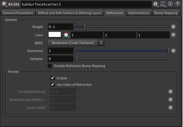
General
Weight
This parameter controls the amount of reflection. 0 means "no reflection". 1 means "strong reflections". In-between numbers will produce weaker-than-perfect reflections.
Color
This parameter allows you to tint the reflections. Setting this to black will make reflections invisible.
BRDF
Allows you to choose the technique for simulating physically correct rough reflections. Beckmann is generally considered the standard for a good range of materials, but GGX has a wide specular tail, which is good for chrome materials.
- Ashikhmin-Shirley (legacy)
- Beckmann (Cook-Torrance)
- GGX
- Ashikhmin-Shirley
The legacy BRDF option uses a non-linear looking glossiness fall-off and exists to maintain compatibility with 1.0 materials.
Glossiness
High glossiness means sharp reflections. Lower numbers will make the reflections blurrier.
Samples
Blurry reflections (when "Glossiness" is less than 1.0) will need multiple samples to get a clean "grain-free" result. Higher numbers will reduce any potential grain issues but will take longer to render and vice-versa.
Fresnel
Enable
This enables Fresnel reflectivity weighting, reflection based on the orientation of the camera to the surface.
Use Index of Refraction
When this option is enabled, the IOR value under General Parameters will be used to compute the perpendicular and facing reflection weights. Surfaces with high IOR will have stronger reflections.
When not enabled, the parameters below will be used instead.
Facing Reflectivity
This controls the strength of reflections when viewed head on, 0 degree angle from the surface. The values range between 0.0 and 1.0. Typically, metals will have a high setting, with a perfect mirror being 1.0. Most materials with reflective coats, however, should have relatively low values, which is why the default is 0.2.
Perpendicular Reflectivity
This controls the strength of reflections when viewed at a 90 angle from the surface. In keeping with the Fresnel effect, this should always bet set to 1.0 so that reflections will be stronger when viewed at shallow angles.
If the Facing and Perpendicular values are the same, then the Fresnel effect will be disabled and there will be equal reflection, regardless of viewing angle.
Curve Falloff
This controls how the facing and perpendicular reflected strength transitions between one and the other. Higher values produce a 'tighter' transition.
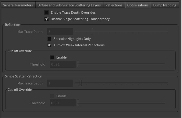
Optimization
Specular Highlights Only
When this parameter is enabled, only reflections from lights will be computed. I.e. no other object in the scene will show through the reflections. This is faster than computing full reflections and in some cases it might be desirable if reflections look "too busy." However, it will also introduce visual inconsistencies especially if other materials in the same scene are configured to use full reflections. In these cases, this parameter should be enabled.
Enable Trace Depth Overrides
This enables the Max Reflection Trace Depth parameter. When not enabled, the global trace depth will be used.
Max Trace Depth
This parameter controls the trace depth for reflection rays shot from this material. If the reflections of a material are not very defined (meaning: they are blurry because of the glossiness parameter or have a low weight), then multiple reflection bounces can be a waste of rendering time. This parameter allows the user to reduce the trace depth and speed up rendering.
Cut-off Override Enable
This parameter allows you to override the global cut-off setting for reflections.
Cut-off Override Threshold
When the reflections of a material are very dark (because of low "Weight" or "Color" values) they contribute very little to the final image. This parameter defines what is considered "very dark" at which point no more reflection rays will be shot - which will speed up rendering. Scenes containing very strong lights might need this parameter set to very low values such as 0.0001 in order to avoid early termination of tracing which can produce a grain-like effect.
Bump
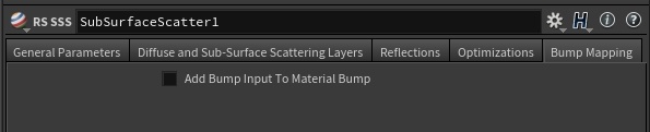
Add Bump Input to Material Bump
This is a legacy option which can have a bump mapping node connected straight to the material. When this parameter is enabled, any bump mapping node results connected to this shader will also be added to the bump mapping results of the material.
Bump Input
Connect your bump map here.
Sub-Surface Scattering in Detail
SSS Rate in Detail
One of the most important SSS quality factors is the "Rate" parameter. The SSS rate parameter looks similar to the antialiasing min/max rates. Using the "Low" setting translates into fewer points, less memory and faster SSS generation times. On the negative side, it also means that small details might be missed! Missed geometry is an undersampling artifact - very similar to the aliasing artifact that happens when a scene is not using high enough antialiasing settings.
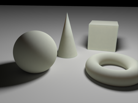
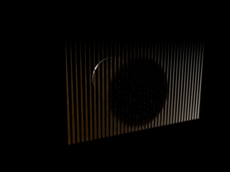
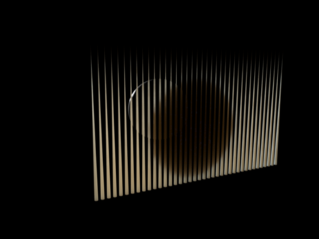
To demonstrate the effect of the different rates, we use the following scene which contains a set of very thin cones shadowed by a sphere. The cones are assigned an SSS material with a very small "Scatter Radius". We have also disabled all GI. The reason we use a small radius and no GI is to ensure that the points have enough SSS contrast in them to better demonstrate the potential issues with the rate setting. Generally speaking, if the SSS radius is large (for a more 'waxy' look) or if the lighting has less contrast (because of GI), the issue is much less apparent.
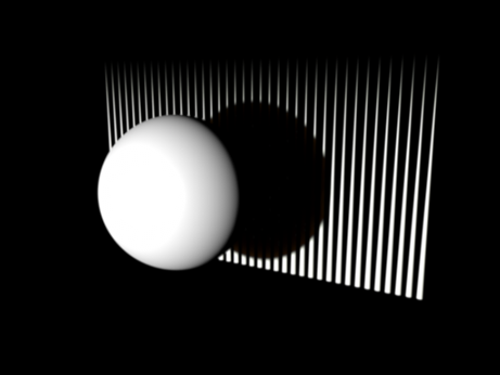
The scene setup
|
|
|
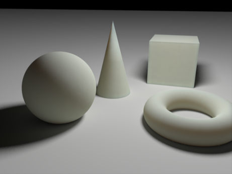
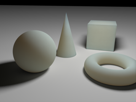
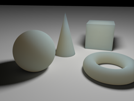
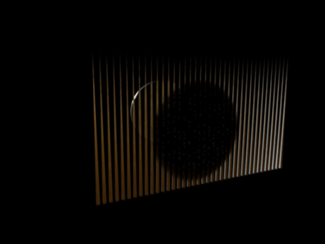
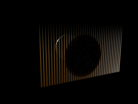
| The scene rendered from behind the cones rendered with the "Low" rate. Compared to the next scenes, it is a bit darker and suffers from 'splotches' | Now rendered with the "Medium" rate. The cones look brighter (this is a more correct result) but there are still splotches in the thinner parts of the geometry (the tips of the cones). | Rendered with a "High" rate. The splotches are improved – especially near the tips of the cones. |
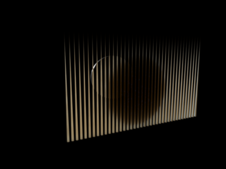
Like mentioned above, if the radius was larger there would be less of an issue even at low rates. This is shown below. Please note that the scene is now brighter overall because light is allowed to travel unobstructed within the objects.
|
|
|
|
|
|

|
| Rate set to "Low". While not perfect (slightly darker than it should be), it's visually more acceptable than the scene using the narrower radius. | Rate set to "Medium". Very slight artifacts on the tips of the cones. | Rate set to "High". No immediately visible artifacts. |
Sub-Surface Color And Scatter Color in Detail
On the shader side of things, the most important parameters for defining the SSS look are the two colors (sub-surface and scatter) and the scatter radius.
When light hits an SSS material, part of it immediately bounces away. The remaining light enters the object, scatters inside it and then exits at some point. The "subsurface" color controls the parts of the light will immediately bounce away while "scatter" color is a tint for the remaining light that will scatter inside the object.
To demonstrate what the previous sentence means, let's take a look at the pictures below. The scene is lit using a purely white light source. Also, all spheres have a "scatter" color set to white. This means that any light entering the object will by tinted by white, i.e. it won't get tinted at all. The sphere "subsurface" colors are set to be red (0.95, 0.5, 0.5), green (0.5, 0.95, 0.5), blue (0.5, 0.5, 0.95) and white (0.95, 0.95, 0.95). Notice that we have intentionally left some gray in all the colors (hence the 0.5 values in there). Also note that we avoid maxing out any of the RGB color channels which is why we use 0.9 instead of 1.0.
Even though using perfectly primary colors is legal, it can make it really hard to get predictable and adjustable results.
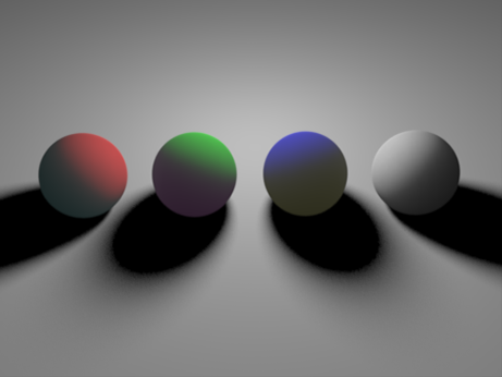
Spheres set to Red, Green, Blue and White "subsurface" colors. All use a "scatter" color of white (0.95, 0.95, 0.95)
The fact that there is cyan, magenta and yellow on the dark side of the first three spheres might seem puzzling at first but there's an explanation. The first sphere used a red sub-surface color which means that a percentage of red light was bounced away. If you remove red from white, the remaining color becomes cyan (the more red you remove). Similarly for the green sphere, green light was removed so magenta was left.
Now let's look at the opposite case, where all "subsurface" colors are set to white and the "scatter" colors are tinted:
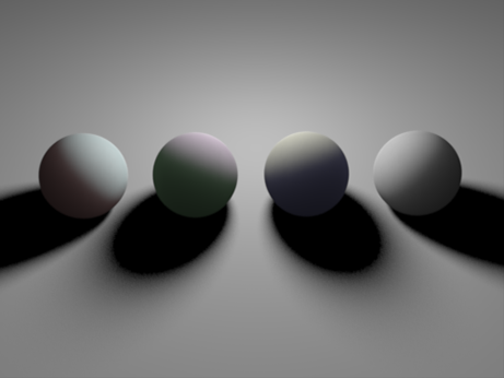
Surface colors all set to white. "Subsurface" colors were set to Red, Green, Blue and White.
Even though the result is much dimmer here, you can tell that the exiting color on the first sphere is Red, on the second is green and the third is blue. However, another puzzling thing is happening here: the first sphere appears to have a bright cyan hue, the second is bright magenta and the third is yellow! The reason for this is similar to the reason given above: when light enters the object, parts of it travel very little and come back off white others continue forward. The parts that travel a lot become "scatter" color, while the parts that exit very close to point of entering become what remains of that "scattering" color.
Some of the details above are not super-important when you use the SSS node but it sometimes help to understand why you might get colors other than the two colors that you specified.
If these tinting effects are undesirable you can 'cancel' them by adjusting the colors. For example, on the first image on the red sphere: If you don't want cyan to come through the other side of the sphere, you can try making "scatter" color red. This will 'tint' the exiting light red which will diminish the cyan hue.
This was done on the first three spheres below. The result looks very saturated because we have used "scatter" colors such as (0.95, 0.0, 0.0) and (0.0, 0.95, 0.0). I.e. we have completely cut-off all color except for red. If this effect is not needed, you can try leaving a bit of color on the other channels and reclaim some gray.
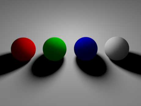
"Scatter" colors adjusted so that no unexpected colors appear on the dark side of spheres
Scatter Radius in Detail
The other parameter that controls the SSS look is the scatter radius. That value is multiplied by the "Scale" value on the "General Parameters" and defines how deep light can travel into the object. The larger this value, the more 'waxy' the effect will look like. This parameter should be set in world units. To give you an impression of the scene scale, the sphere has a radius of 1.0.
The examples below demonstrate the effect of this parameter:
|
|
|
|
Scatter Radius 0.5 |
Scatter Radius 1.0 |
|
|
|
|
Scatter Radius 4.0 |
Scatter Radius 8.0 |