Distance
Overview
| Paper textures from ambientcg.com |
The Distance shader measures the distance to the nearest object and that measurement can be used to drive creative shader effects in the scene. The Distance shader can be textured and Trace Sets even let you specify which objects are included in the distance calculation and which are not, providing a high level of control.
The Distance shader is currently not compatible with bump mapping.
Distance Catchers and Distance Targets
On this page an object with a distance shader applied to it is called a "distance catcher," you can think of this like a shadow catcher, it is an object that the distance effect is recorded onto. On the other hand, the objects that have their distance measured are called "distance targets" — like an object included in the trace set.
How it works
The Distance shader uses Redshift's ambient occlusion (AO) kernel to shoot probe rays from all across the surface of a distance catching object out into the scene. When a probe ray intersects with a valid distance target the distance to that object is stored in the location from where the probe ray originated. After enough rays are shot a general estimate of the distance to the nearest distance target is gathered for the entire distance catching surface, resulting in a black and white map that visualizes this information.
Face Normals
When Interior Controls are enabled, the direction of a distance target's surface normals are used to differentiate between the interior and exterior of an object — back faces are considered the inside of a mesh.
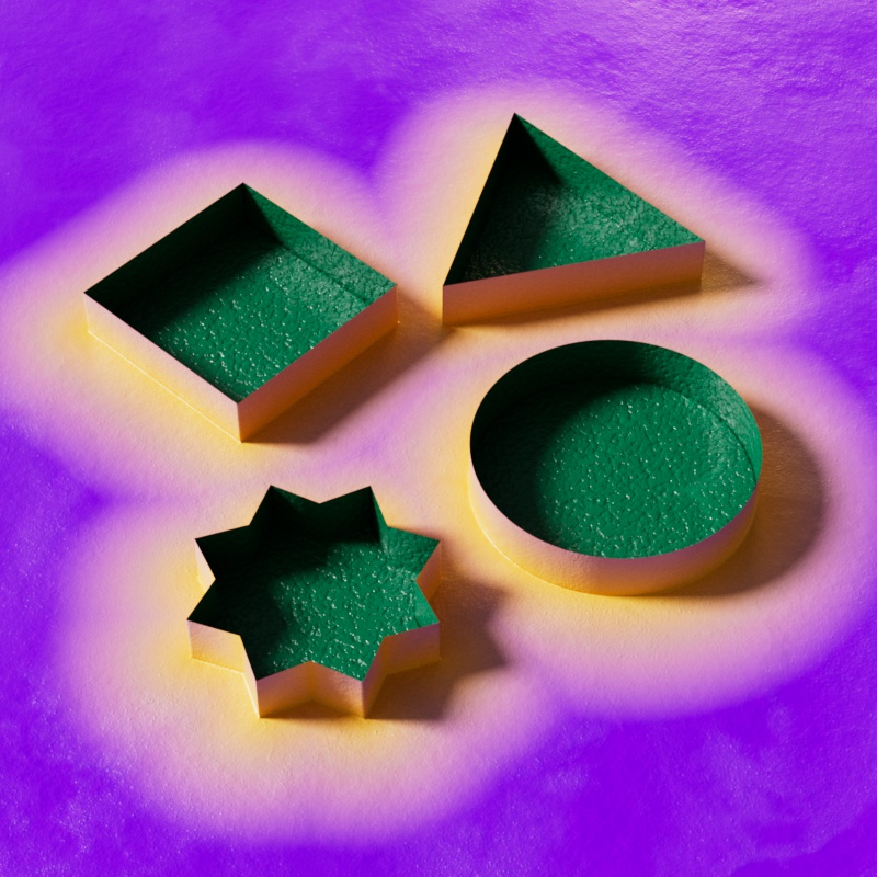
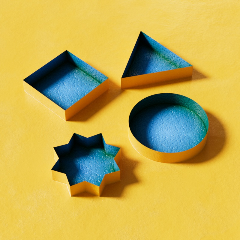
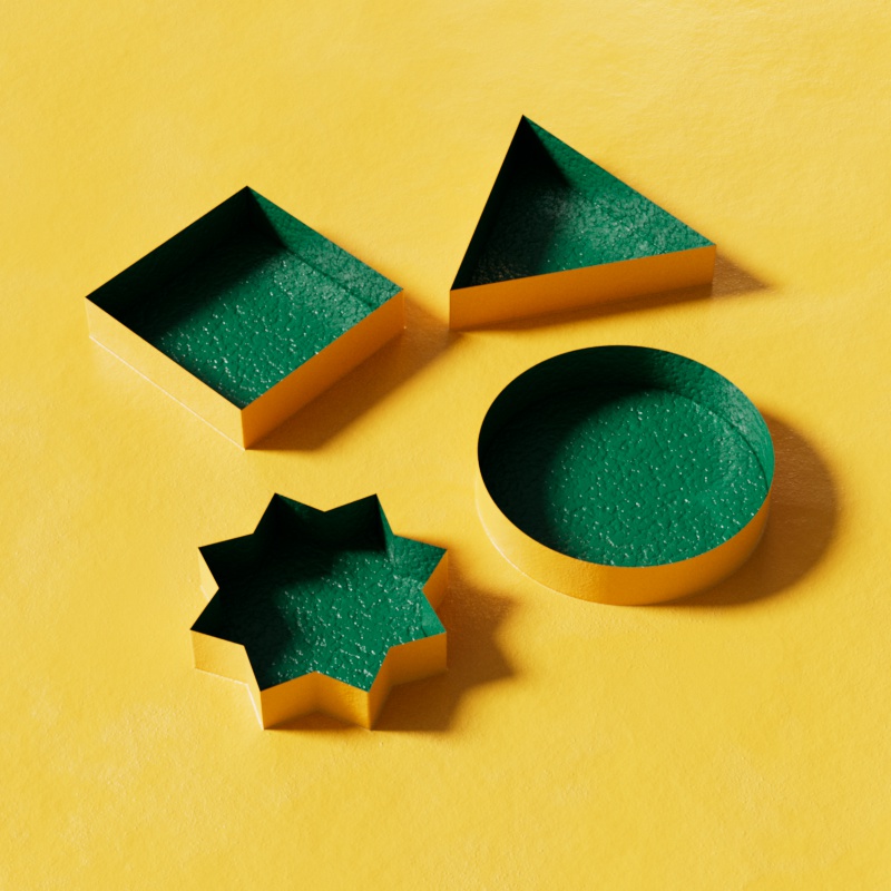
In the example below a single plane spins above a ground plane, both objects have the same distance shader applied to them. Since the plane has no thickness one side of it is considered the exterior and one side is considered the interior. The side that is considered the exterior is the front facing side of the plane, this is indicated with the white spike that is sticking out of one side of the plane. The distance shader in this example uses yellow for the General (Exterior) Near Color and green for the Interior Near Color. Purple is used for both the General and Interior Far Colors so that it fades out to the same color for exterior and interior faces.
Take note of two key things:
-
The ground plane catches distance from the rotating plane and the Interior color (green) stays locked on the back facing side of the plane while the Exterior color (yellow) stays locked on the front facing side.
-
The rotating plane catches distance from the ground plane and it only exhibits the exterior color (yellow) because it is only catching distance from the front faces of the ground plane which are facing upwards.
| Interior vs Exterior Distance Shading |
Geometry matters
The Distance shaders can measure most visible geometry in a scene but it cannot detect volumes, splines, particles, or null objects. Of course, you can always create proxy geometry for volumes, extrude geometry along a spline, generate objects for each particle, or parent geometry to a null object — all of these are sufficient workarounds for the Distance shader. The Distance shader can measure distance to objects that are not visible as long as they continue to be visible to AO rays, for more information, see the "Invisible Objects" section in the Examples area on this page.
Since the distance effect is based on the shape of the geometry make sure your objects have enough subdivisions to support the look you want to achieve.
| Subdivided sphere |
Examples
Colorization and textured distance
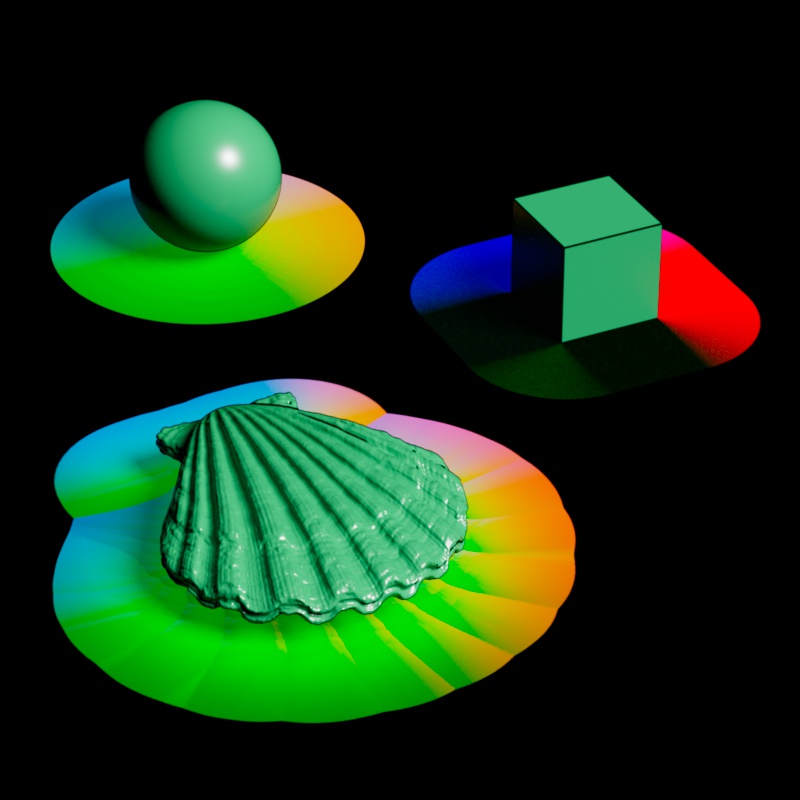
The most common output for the distance effect is its OutColor, using the default settings produces a simple black to white color gradient that is perfect for masks and driving other effects with a ramp. To colorize the distance effect all you need to understand is how a black and white gradient maps to a custom ramp.
Think of the black and white distance output like a black and white horizontal ramp, the darkest parts map to the left side of the ramp, the midtones map to the middle area, and the brightest parts map to the right side. In the example below, note how the black and white ramp at the bottom matches up directly to the colorized ramps and the subsequent colorization of the distance effect.
| Distance colorization |
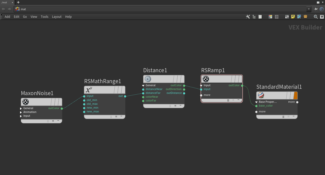
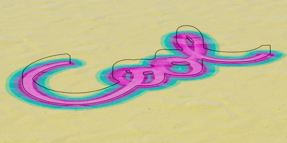
It's also easy to vary the distance effect by driving the near or far distance input with a texture, in the example below an animated Maxon noise is used.
| Textured distance |
Colorization is accomplished simply by driving a ramp with the distance shader's OutColor, while textured distance effects are most easily handled by taking a texture (in this example a Maxon noise) and using something like a change range to control the minimum and maximum distance values. Both of these setups are demonstrated in the image below.
|
Invisible Objects
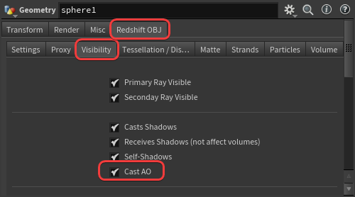
Because the Distance shader uses the AO kernel to measure distance it can detect objects even if they are invisible. As long as an object has "Casts AO" enabled in its Visibility settings then it can be included in the distance measurement even if "Primary Visibility" and all other visibility options are disabled. On the other hand, disabling "Casts AO" is a nice way to ensure that an object is never included in the distance process.
|
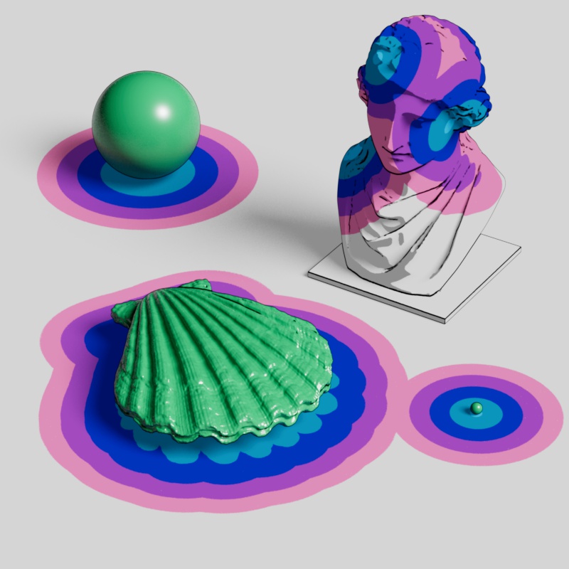
With this in mind, you can create cool effects and essentially paint on distance catchers with invisible objects. In many of the example images on this page, a statue is painted by 4 invisible spheres as revealed below.
|
|

|
|
| Write-On effect | Write-On hidden geo | Painting a statue | Statue spheres |
Height
The distance shader can capture a height map style effect on objects with deep peaks and valleys. This can be accomplished by enabling the Include Backside option, having the distance catcher exclude itself, and using a distance target with a very consistent surface location — like the ground plane in the example below.

|
| Height from the ground plane |
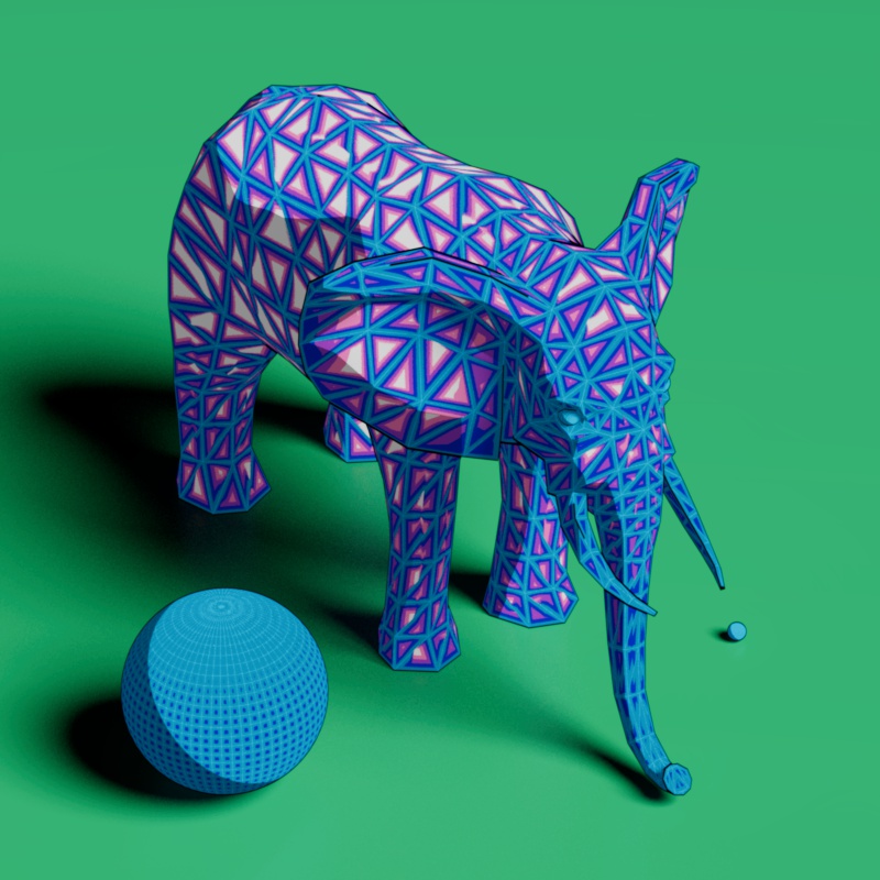
Wireframe
A wireframe style effect can be created when using a very short far distance while a distance catcher is set to a mode that allows it to detect itself. Include Backside should also be enabled, in most situations, for best results.
|
| Short maximum distance |
Parameters
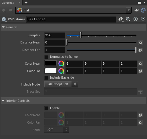
|
General
Samples
Sets the number of samples used to calculate the distance. Higher values result in higher quality and more accurate distance calculations but it takes longer to render. Lower values are less accurate but they are faster to calculate, finding the right balance is highly dependent on the scale and complexity of objects in the scene, how far the maximum distance is set, and the visual style of the distance output.
High sampling counts in the thousands are not uncommon for the distance shader, do not hesitate to increase the sample count to 2000 or higher depending on your scene and the effect you are after. Note that this will affect IPR feedback.
Large objects are more likely to be hit by samples while small objects are less likely to be hit, meaning it takes fewer samples to adequately resolve a distance calculation for large objects compared to small ones. In the example below, note how the small spheres take many more samples before the distance effect looks clean. Similarly, the stepped color gradient requires more samples to look nice and sharp where as the smooth color gradient is more forgiving with fewer samples.
| Distance Samples: 1 - 1000 |
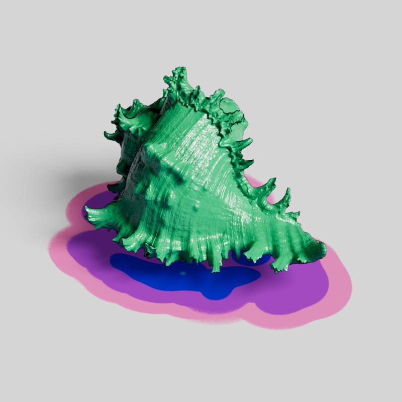
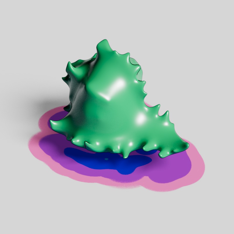
The same holds true for large objects with small details, the overall size and shape of an object is easier to catch with fewer samples than small surface details. If it's not important to catch each detail you can create a simplified proxy object used for distance calculation, this will reduce the number of samples needed to produce a clean result. You have two options to control if an object is included in distance calculation, by using the trace set functionality built into the distance shader or stopping an object from contributing to AO calculation. Since distance is calculated using Redshift's AO kernel all you need to do is disable "Casts AO" in the high detail Object's Visibility setting and it will never be considered a distance target — regardless of whether it is included in the distance trace set.
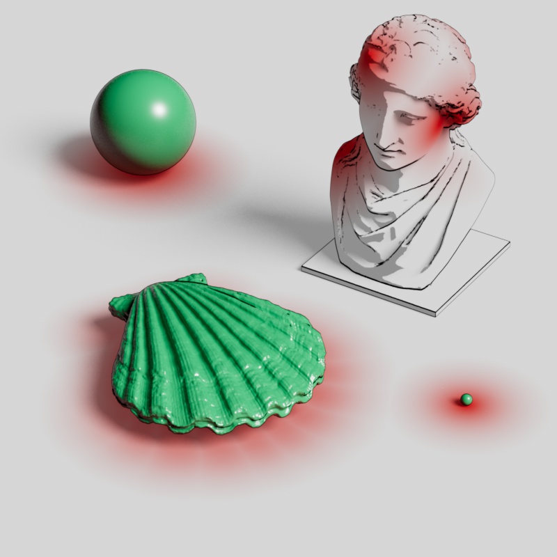
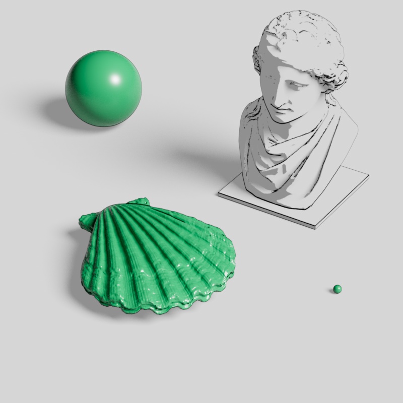
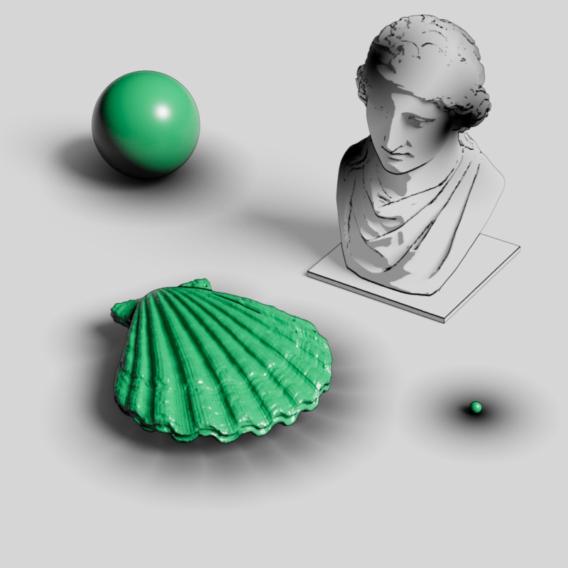
In the example below, a detailed shell model is demonstrated with and without a proxy object for distance calculation. Each example uses the same number of samples, but when the proxy object is used the results are cleaner while sacrificing some accuracy in capturing all of the small geometric details. Notice how the distance effect beneath the shell is less defined and noisier than when the distance proxy is used while the overall shape remains very similar.

|
|
|
| Detailed object without distance proxy | Detailed object with distance proxy | Distance proxy preview |
Distance Near
Scene Units
Controls how far in scene units each sample is clamped after the starting distance (0) for each probe ray, in other words this marks the beginning of the distance effect. When set to 0 the distance transition starts immediately, however when using a value greater than 0 the distance output is clamped until the near distance is reached. This compresses the transition as it is pushed closer to the far distance clamp. The near distance can also be textured.
In the examples below, the near distance is increased from 0 to 50 or 99 scene units while the far distance is always left at 100. As Distance Near increases the color ramp is pushed closer to Distance Far at 100 scene units and the area from 0 units up to the near distance is clamped to the light blue color on the ramp. In the cylinder example, there are two rings of black spheres provided for reference, the ring closest to the cylinder is 50 units away from the edge of the cylinder while the other is 100 units away. One example has the near distance set to 50 and the other set to 99, as you can see, this perfectly matches up with expected distance illustrated by the rings.
| Distance Near: 0 - 50 Distance Far: 0 - 100 |
0 - 99 |
Distance Far
Scene Units
Controls how far in scene units the distance is measured before the result is clamped, in other words this marks the end of the distance effect. Higher values result in a larger effect while lower values compress it closer to the near distance. More samples are required as the distance is increased.
In the first example below, note how there is more noise around the small sphere as the distance is increased. In the cylinder example, there are two rings of black spheres provided for reference, the ring closest to the cylinder is 50 units away from the edge of the cylinder while the other is 100 units away. The far distance can also be textured for fun effects, in the example below an animated Maxon noise drives a change range from 20 to 50 units which is connected to the Distance Far input.
| Distance Far: 0 - 100 Distance Near: 0 |
0 - 100 | Animated noise texture controlled by change range |
Normalize to Range
Only affects the OutDistance scalar output.
When enabled, the OutDistance range is normalized to a 0 to 1 range. When disabled, the OutDistance range is always output in raw meters.
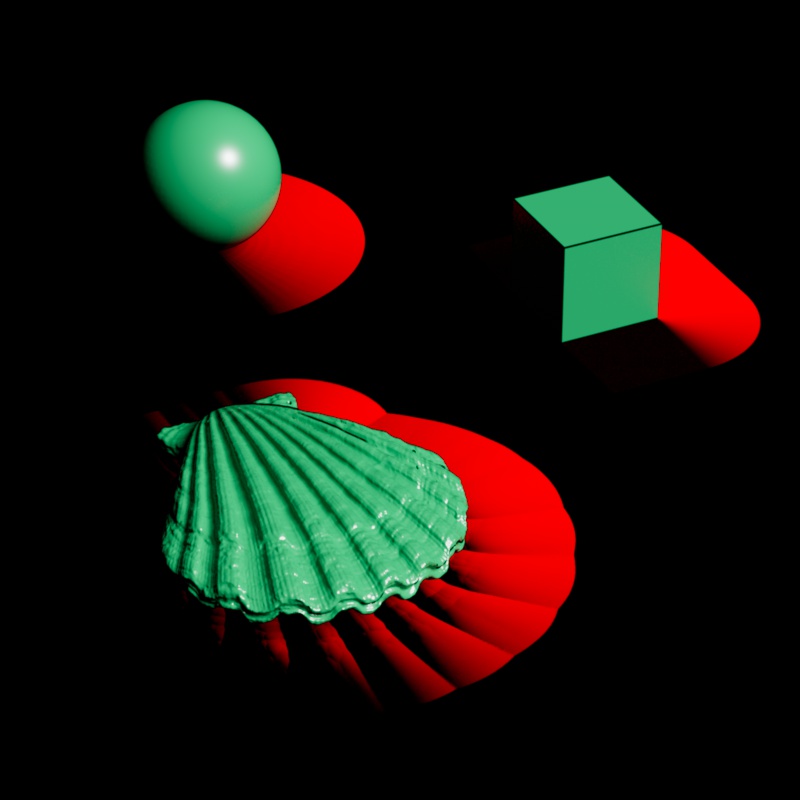
Color Near
Controls the color used for exterior distance targets from 0 scene units up to the Distance Near value. After the near distance is reached the near color begins to blend in more of the far color.
When Interior Controls are enabled, this controls the near color for exterior faces.

|
|
|

|
| Color Near: Black Color Far: White |
Red | White | Textured |
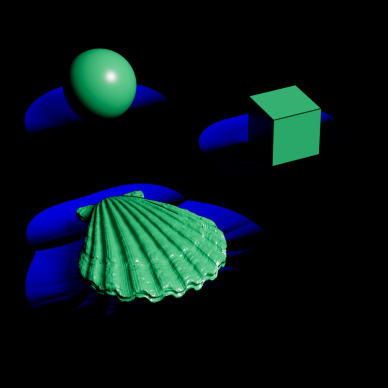
Color Far
Controls the color used for exterior distance targets from the Distance Far value and beyond. When the distance is closer than the far distance, the far color blends in more of the near color.
When Interior Controls are enabled, this controls the far color for exterior faces.
|

|
|

|
| Color Far: White Black |
Red | Black | Textured |
Include Backside
When enabled, objects on the backside (opposite the surface normal) are included in the distance calculation. When disabled, by default, objects on the backside are ignored — this means once an object intersects with a distance catcher any part of a distance target on the inside becomes invisible to the distance shader.
Notice, in the example below, that when Include Backside is enabled the shell can be seen smoothly approaching the surface of the plane before it breaks through the surface. However, when disabled, the distance effect appears abruptly as soon as any part of the shell rises above the surface and when it is entirely under the surface there is no effect at all.
| Include Backside: Disabled (default) | Enabled |
Include Mode
Controls which objects are considered distance targets
-
All Except Self: Includes all objects in the scene but distance catchers do not consider themselves distance targets. Note, separate distance catchers will still detect each other.
-
Only Self: Distance catchers only consider themselves as distance targets, this can be useful for objects only detecting their own geometric features. With this mode, Include Backside should generally be enabled.
-
All: All objects are considered distance targets, distance catchers also include themselves.
-
Trace Set: The Trace Set exclusively controls which objects are considered distance targets, individual objects can be included or excluded. This mode offers the most customization.
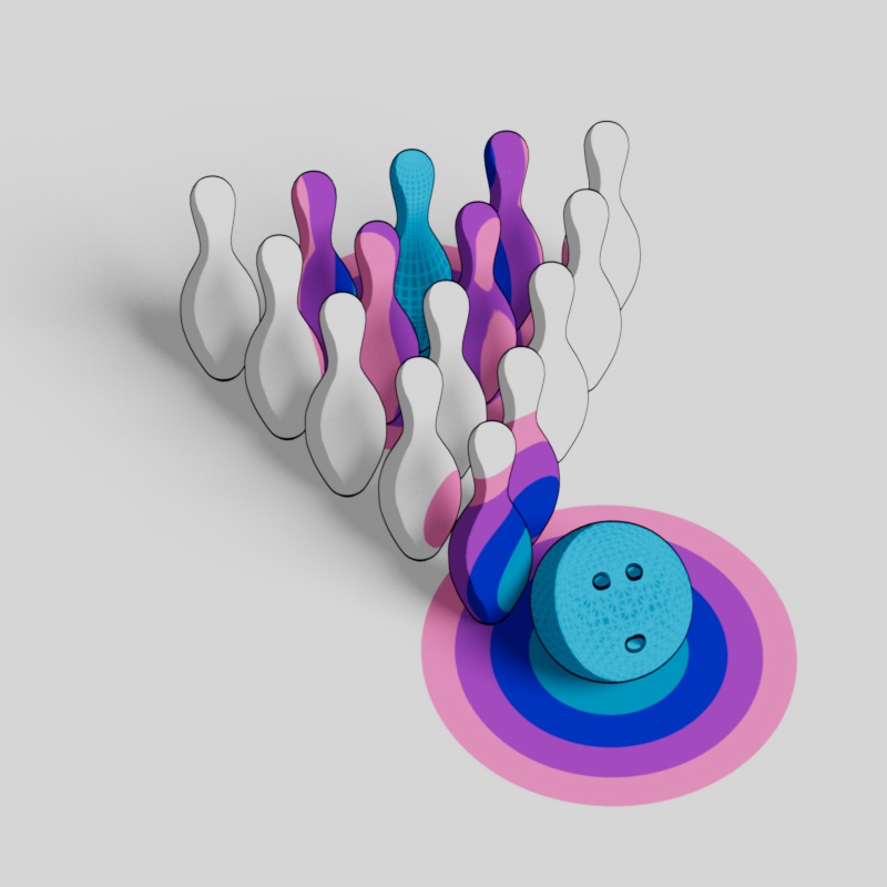
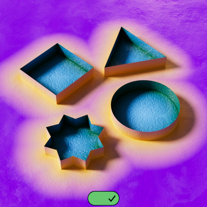
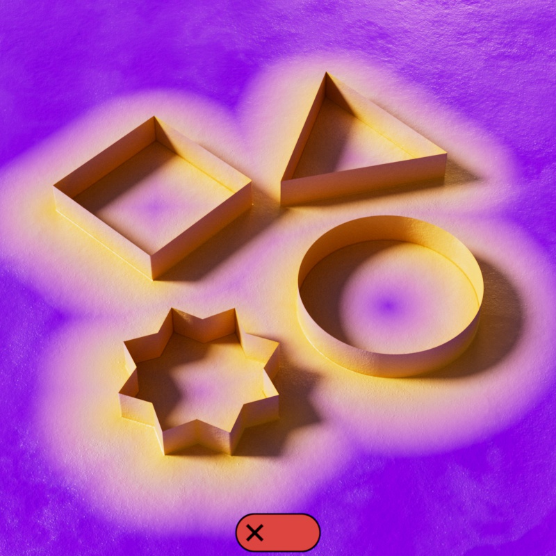
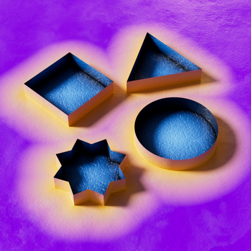
In the examples below, all objects are distance catchers, every object in the scene (including the ground plane) uses the same material and Include Backside is enabled. Note that when the objects consider themselves distance targets they turn bright blue and a wireframe effect becomes visible as they detect their own geometric shape — this takes priority over detecting any other object because nothing in the scene is closer than the points on the object itself. In the Trace Set example, only the bowling ball and the back middle bowling pin are included in the Trace Set making them the only 2 valid distance targets in the scene.

|

|

|
|
| Include Mode: All Except Self | Only Self | All | Trace Set |
Trace Set Mode
Only applicable when Include Mode is set to Trace Set.
Controls how the objects listed in the Trace Set are used in the distance calculation. When set to exclude, all objects are considered distance targets except the objects in the Trace Set. When set to include, only objects in the Trace Set are considered distance targets — all others are ignored.
In the example below, the two shell models are the only objects listed in the Trace Set. When set to Include, the shells are the only objects that affect the distance shader. When set to exclude, only the spheres affect the distance shader.

|

|
| Trace Set: Include Trace Set: 2 Shell objects |
Exclude |
Trace Set
Only applicable when Include Mode is set to Trace Set.
Objects can be added here to control which objects are affected by the Trace Set Mode, whether these objects are included or excluded in the distance calculation is dependent on the Trace Set Mode.
Interior Controls
Enable
When enabled, the inside of a mesh is distinguished from the outside. The inside of a mesh is determined by the direction of the surface normals, backfaces are considered the inside of a mesh.
-
Color Output - The interior is rendered using the Interior Color Near and Far controls and the exterior uses the General Color Near and Far controls.
-
Out Distance Output - Interior distances use negative values while exterior distances use positive values.
When disabled — by default, there is no difference between the inside and outside of a mesh — all sides are rendered as if they are exterior.
-
Color Output - The interior and exterior are both rendered using the General Color Near and Far controls.
-
Out Distance Output - Interior and exterior distances both use positive values.
|
|
| Interior Controls: Enabled | Disabled |
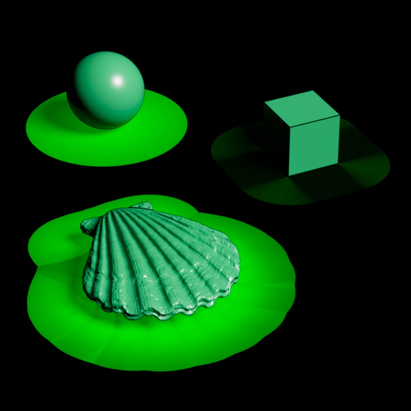
Color Near
Controls the color used for interior distance targets from 0 scene units up to the Interior Distance Near value. After the near distance is reached the near color begins to blend in more of the far color.

|
|
|
| Interior Color Near: Dark Green | Black | Red |
Color Far
Controls the color used for interior distance targets from the Interior Distance Far value and beyond. When the distance is closer than the far distance, the far color blends in more of the near color.
|
|
|
| Interior Far Color: Light Blue | Light Green | White |
Solid
Controls if the Color output blends between the near and far colors or if they are rendered as one solid color.
-
Off (Default) - The colors on the inside are blended between the Interior Color Near and Far and the colors on the outside are blended between the General Color Near and Far.
-
Inside - The colors on the inside are solid using the Interior Near Color while the colors on the outside as blended between the General Color Near and Far.
-
Outside - The colors on the inside are blended between the Interior Color Near and Far while the colors on the outside are solid using the General Color Near.
-
Both - The colors on the inside are solid using the Interior Color Near and the colors on the outside are solid using the General Color Near. This can be used for as an easy way to create a black and white mask to differentiate between the interior and exterior.

|
|
|
|
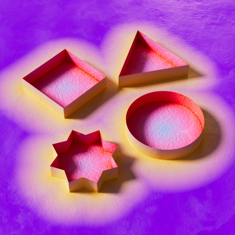
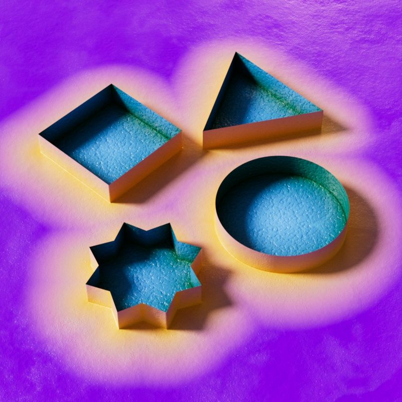
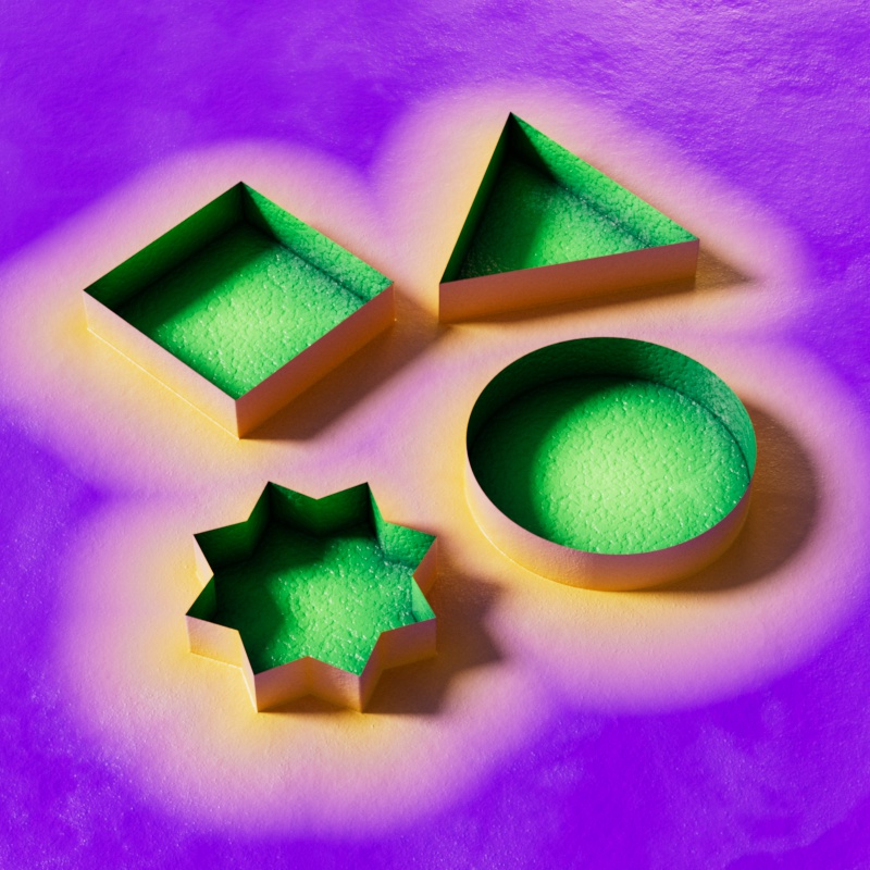
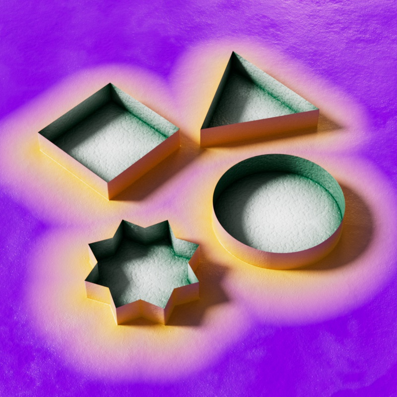
| Solid: Off General Color Near: Yellow General Color Far: Purple Interior Color Near: Green Interior Color Far: Light Blue |
Inside | Outside | Both |
Outputs
outColor
Provides a normalized output which is a blended result of the near and far colors based on distance. This is the most common output and can be used to drive a ramp and other shaders for creative effects and masks.
outDirection
Provides a vector output indicating the direction to the closest object. Each axis corresponds to a color channel, red = X, green = Y, and blue = Z. This can be used like a mask to control effects in a specific direction.
The vector output is both positive and negative, corresponding to the opposing sides of each axis, since negative values appear black in the frame buffer you will only see.
|
|

|
|
| Raw Output: RGB = XYZ | R = X | G = Y | B = Z |
To reveal both sides of an axis, an Abs (absolute) math node can be used to convert the output to all positive values.

|

|
|

|
| Raw Output + Abs: RGB = XYZ | R = X | G = Y | B = Z |
outDistance
Provides a scalar output in meters indicating the distance to the closest object. This output can be normalized by enabling the "Normalize to Range" option.
When you enable Interior Controls, exterior distances use positive values and interior distances use negative values.