THIS SHADER IS DEPRECATED!! PLEASE USE THE REDSHIFT MATERIAL SHADER INSTEAD!
Table Of Contents
- Introduction
- Diffuse
- Reflection
- Primary / Secondary Reflection
- Fresnel (Primary / Secondary)
- Common Reflection Parameters
- Anisotropy
- Refraction
- Ambient Occlusion
- Optimizations
- Miscellaneous
Introduction
The architectural material is an 'uber shader' that attempts to cover the most commonly used material features in order to make a wide range of different material types, while maintaining energy conservation and having a 'physically correct' BSDF.
It has built in support for Ambient Occlusion ( see Ambient Occlusion documentation for a super-set of this shader's implementation), Diffuse Roughness, two Specular/Glossy reflections, Transparency/Refraction, depth-based fogging effects and localized, but familiar optimization options (see Optimization Options for detailed information on global cut-off).
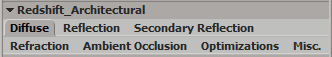
Diffuse
The architectural material is affected by both direct and indirect lighting. This tab controls the diffuse properties of the lighting model.
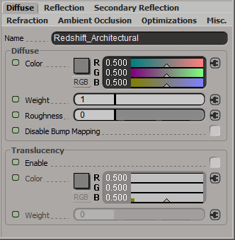
Color
This defines the color of the surface when reflecting diffuse direct lighting or indirect global illumination and essentially a tint. Setting this to black means no diffuse lighting.
Weight
This scales the overall amount of diffuse lighting, with zero meaning no diffuse and one meaning maximum diffuse.
Roughness
This controls the 'roughness' of the diffuse lighting and is useful for simulating matte/dirty surfaces. We implement the Oren-Nayar shading model to emulate rough surface micro-facets. A roughness of 0.0 is equivalent to a perfectly smooth surface, or traditional Lambert shading.
Disable Diffuse Bump Mapping
This option allows you to switch to using the default un-bumped surface normals for direct and indirect diffuse lighting calculations.
Translucency
Enable
This enables double-sided lighting, useful for materials such as leaves.
Color
This defines the color of the surface when reflecting translucent diffuse direct lighting, i.e. light that has travelled through the surface first. For more realistic translucency, see the Sub Surface Scattering shader doc.
Weight
This scales the overall amount of diffuse translucent lighting.
Diffuse in Detail
|
|
|
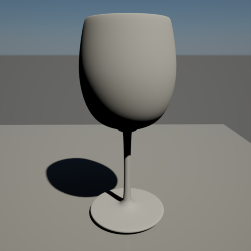
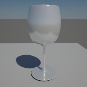
| This demonstrates diffuse light reflection, with no roughness ('Roughness' of 0.0) and a diffuse tint of (0.8, 0.8, 0.8). No Global Illumination is enabled. |
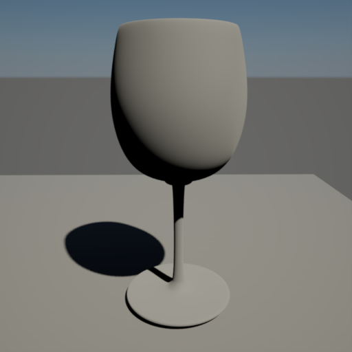
Now 'Roughness' is set to 1.0. |
Reflection
At its simplest, when light interacts with a surface, some of it is scattered under the surface and exits (
not covered here, see Sub Surface Scattering shader), some of it is transmitted (
specular/glossy refraction) and some of it is reflected (
diffuse/specular/glossy). This tab controls how light is to be transmitted and reflected.
In order to be physically correct, this shader attempts to preserve energy, whereby the amount of diffuse, reflection and refraction from the surface is automatically balanced such that
Diffuse + Reflection + Refraction <= 1.0
An example of this kind of preservation is to take a perfectly reflective mirror, where it doesn't matter how transparent or diffuse you may have set the parameters, the strong reflection will always win. In essence the rule is:
- Incoming energy is first reflected.
- Any leftover energy that was not reflected (e.g. if the surface is not perfectly reflected or has Fresnel) is transmitted (refracted).
- Any leftover energy that was neither reflected nor transmitted contributes to the diffuse.
In other words, Reflection and Refraction will always win over Diffuse.
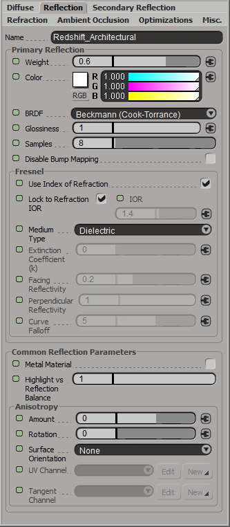
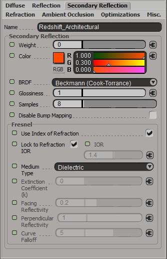
Primary / Secondary Reflection
Weight
This parameter controls the amount of reflection. Zero means "no reflection". One means "maximum reflection". Note that a weight and color of 1.0 does not necessarily guarantee a completely reflective object, unless Fresnel rules permit.
Color
This controls the tint of specular/glossy reflections and traditional specular "highlights". Setting this to black means light will not be reflected and thus disables the effect.
BRDF
Allows you to choose the technique for simulating physically correct rough reflections. Beckmann is generally considered the standard for a good range of materials, but GGX has a wide specular tail, which is good for chrome materials.
- Ashikhmin-Shirley (legacy)
- Beckmann (Cook-Torrance)
- GGX
- Ashikhmin-Shirley
The legacy BRDF option uses a non-linear looking glossiness fall-off and exists to maintain compatibility with 1.0 materials.
Glossiness
High glossiness means sharp or 'specular' reflections. Lower numbers will make the reflections blurrier and 'rougher', with 0.0 yielding an almost diffuse look.
Samples
Blurry reflections (when "Glossiness" is less than 1.0) will need multiple samples to get a clean "grain-free" result. Higher numbers will reduce any potential grain issues but will take longer to render and vice-versa.
Disable Prim. Refl. Bump Mapping
This option allows you to switch to using the default un-bumped surface normals for direct and indirect reflection rays.
Reflections in Detail
|
|
|
|
| This example of specular Fresnel reflection, with a 'Facing Reflectivity' strength of 0.2 and a 'Glossiness' of 1.0, which gives us a shiny plastic look. | This example shows specular mirror reflection, with a Facing Reflectivity strength of 1.0 and a Glossiness of 1.0, which gives us perfect specular reflection. Note how the reflection has 'taken away' all the diffuse lighting, this is because we are preserving energy, meaning we do not reflect more light than we receive. | The example now shows glossy Fresnel reflection, with a Facing Reflectivity strength on 0.5 and a Glossiness of 0.6, which gives the reflected surface a certain amount of roughness. As with transparency, here we use 64 samples to get good looking results. |
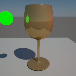
Below are examples of how 'specular highlights' look for different kind of lights and different kinds of glossiness. In all examples we have a green area light and a red point light.
|
|
|
|
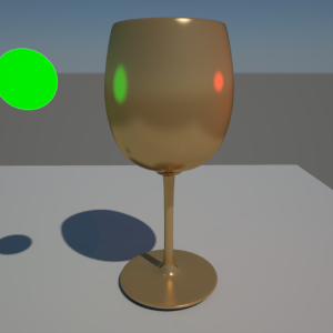
| This example has perfect specular reflection 'Glossiness' of 1.0. Both lights contribute a small amount of diffuse, but see how the point light specular reflection is not visible? This is because it is infinitesimally small. | This example has a 'Glossiness' setting of 0.5, simulating a rougher surface. Now we can see the point light and the reflections look more blurry. |
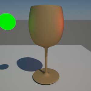
This example has a 'Glossiness' setting of 0.0. This is 'maximum roughness', so the reflections now look almost diffuse. |
Fresnel (Primary / Secondary)
In nature reflections appear strongest when viewed at shallow angles. The Fresnel equation attempts to simulate this effect. What this means is that you will see the diffuse, reflection and refraction balance change, depending on the viewing angle between the surface and the camera.
Use Index of Refraction
This is the default, because in nature, the Index of Refraction of a dielectric material determines how strong or weak the Fresnel effect is at different viewing angles. If you un-check this, because you want to control the refraction effect separately from the reflection strength, then you can bypass the Fresnel equation with the options presented below the Extinction Coefficient.
Lock to Refraction IOR
This means use the refraction IOR to compute the Fresnel reflection. This is the default, because ideally the reflection and refraction IOR should be the same for dielectric materials.
IOR
Alternative reflection IOR for Fresnel calculation when the 'Lock to Refraction IOR' option is disabled.
Medium Type
This allows you to specify what kind of medium the material is, which determines how the Fresnel reflectance amount is calculated. There are two types:
- Dielectric (typically transparent materials, such as glass, water)
- Conductor (typically solid, metal materials)
Extinction Coefficient (k)
This parameter is required for 'Conductor' materials.
Facing Reflectivity
This controls the strength of reflections when viewed head on, 0 degree angle from the surface. The values range between 0.0 and 1.0. Typically, metals will have a high setting, with a perfect mirror being 1.0. Most materials with reflective coats, however, should have relatively low values, which is why the default is 0.2.
Perpendicular Reflectivity
This controls the strength of reflections when viewed at a 90 angle from the surface. In keeping with the Fresnel effect, this should always bet set to 1.0 so that reflections will be stronger when viewed at shallow angles.
If the Facing and Perpendicular values are the same, then the Fresnel effect will be disabled and there will be equal reflection, regardless of viewing angle.
Curve Falloff
This controls how the facing and perpendicular reflected strength transitions between one and the other. Higher values produce a 'tighter' transition.
Fresnel in Detail
Below are examples of the Fresnel reflection effect.
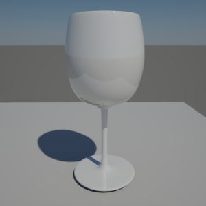
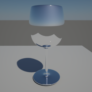
The following examples show the floor surface material at default settings.
|
|
|
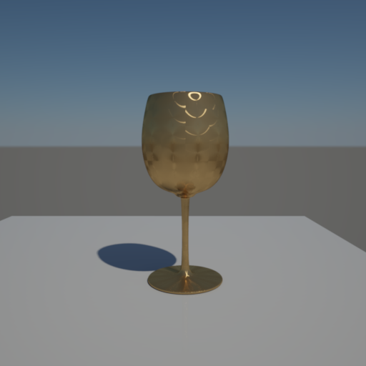
| At a shallow angle, the reflection of the cup and sky is clearly visible. |
Now viewed from a less shallow angle, notice how the Fresnel reflection effect is very weak and the cup and sky are hardly visible. |
Common Reflection Parameters
Metal Material
This tints the reflections with the diffuse color and further brings down the diffuse contribution, which gives reflections a more metallic look.
Highlight vs Reflection Balance
This allows you to control how strong traditional specular highlights are, relative to the ray-traced reflections. Setting this value to 0.0 means no specular highlights will be visible. Setting to 1.0, means fully visible.
Use this control with caution. This should only be used to balance non area light reflections. Area light reflections are calculated using a special technique called Multiple Importance Sampling (MIS) to automatically balance highlights with ray-traced reflections. MIS relies on a setting of 1.0 to work properly. Any other setting means reflected area lights may look too dark at low glossiness, or not visible at all.
Anisotropy
Anisotropy controls the ratio between the 'width' and 'height' of glossy reflections and refractions. It is primarily used for effects such as brushed metal, to simulate the shape and orientation of micro-surface grooves. Visually it has the effect of stretching or contracting reflected highlights.
Amount
This parameter is in the range of -1.0 to 1.0, where 0.0 means no anisotropy ( isotropic reflection/refraction ), negative numbers mean the width of reflections will stretched (u direction), whereas positive numbers mean the height will be stretched (v direction).
Rotation
Use this control to change the orientation of the micro-surface grooves. The values are between 0.0 and 1.0, which represent rotation between 0.0 and 360.0 degrees respectively.
Surface Orientation
In order to apply the anisotropic glossy effect, the shader needs to know the orientation of the surface in u and v directions. There are two ways to specify this:
- From UV Channel ( XSI Only)
- From Tangent Channel
NOTE: 'From UV Channel' means the u and v directions are approximations and will yield faceting, unless the mesh is highly tessellated. If you are mapping a flat surface, this is fine, but it is recommended that you use the 'Tangent Channel' option for curved, or low tessellation surfaces
UV Set
Specifies the UV set to use for anisotropy.
Anisotropy in Detail
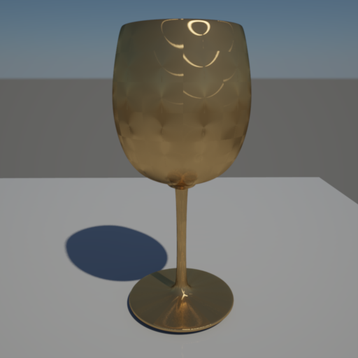
Here is an example of glossy Fresnel reflection, with a 'Diffuse Color' of bronze, the 'Metal Material' checked and a 'pounded metal' texture attached to the Anisotropic Rotation input, with an Anisotropy of -0.8.
Refraction
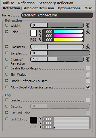
Weight
This parameter controls the amount of refraction. Zero means "no refraction". One means "maximum refraction". Note that a weight and color of 1.0 does not necessarily guarantee a completely transparent object, unless energy preservation and Fresnel rules permit ( see Fresnel section for a description of this behavior ).
Color
This controls the tint of refractions/transparencies. Setting this to black means light does not pass through the surface and thus disables the effect.
Glossiness
High glossiness means sharp or 'specular' refractions. Lower numbers will make the refractions blurrier, yielding a 'frosted' look. Note that this only takes effect if the IOR ( see below ) is a number other than 1.0.
Samples
'Frosted' refractions (when Glossiness is less than 1.0) will need multiple samples to get a clean "grain-free" result. Higher numbers will reduce any potential grain issues but will take longer to render and vice-versa. Note that this only takes effect if the IOR (see below) is a number other than 1.0. A number of 1.0 will yield perfectly specular transmission.
Index of Refraction
This describes how a light ray is bent as it travels from one medium to another. For example, an IOR of 1.0 is correct for a vacuum and roughly close to air at Standard Temperature and Pressure. Water is 1.33, while glass is usually represented by 1.4 (the default). Note that this can also indirectly control Fresnel-based reflection strength ( see Fresnel section for a description of this behavior ).
Disable Refr. Bump Mapping
This option allows you to switch to using the default un-bumped surface normals for indirect refraction/transparency rays.
Thin Walled
This option is useful for modeling materials such as thin glass panes without actually having to model the pane thickness. In this example, you want the IOR to be 1.4 for Fresnel reflections to be realistic, but you don't actually want the ray to bend when it exits the pane, because it wouldn't be noticeable in real life if the pane is thin enough.
Enable Refractive Caustics
When this option is enabled, in conjunction with the global Photon Caustics setting enabled, the object's shadow becomes black and is instead expected to be defined by photon caustics.
In order for this to work as expected, the light must be emitting caustic photons and the object must have caustics casting enabled.
Allow Global Volume Scattering
When Global Volume Scattering is added to the scene, enabling this option allows global fog and light volumes to 'pass through' a refracted medium. However, in real life, an enclosed medium would not be affected by the fog in air. If your model is closed and the normals are correct, un-checking this option will stop global fog and light volumes affecting the enclosed medium.
Refraction in Detail
|
|
|
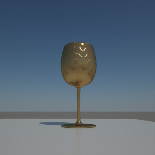
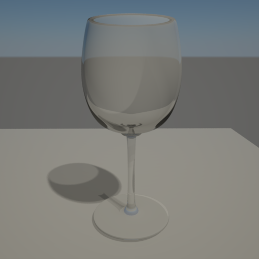
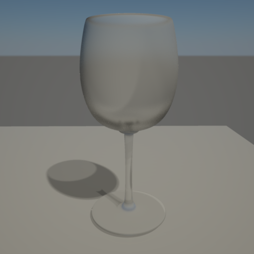
| The image below is an example of refraction, with IOR 1.4, no glossiness (1.0) and a weight of 0.8. As you can see, the light bends as it travels through the glass. Also note the darkness at the base of the glass, this is because we limit how deep our refraction rays can go (see Optimizations tab and Optimizations Options doc). | Below is the same example, but with a 'Glossiness' setting of 0.6 and number of samples set to 64. The lower the glossiness setting, the more 'frosted' the glass looks. Note that the lower the glossiness setting (i.e. the wider the gloss), the more samples you will need to remove noise. |
Fog
Enable
This option enables a 'fogging' effect inside, which is defined by the options below. By default ( when 'Use End Color' is not selected ) this means the object will fog to black, reaching black at the distance specific below.
Distance
When 'Use End Color' is not checked, this defines the distance within the object at which refraction rays will stop and be pure black. When 'Use End Color' is checked, it defines the distance within the object at which the color becomes the 'End Color'. In this case, beyond that distance the fog color attenuates exponentially. Note that a distance of 0.0 means the effect is disabled..
Use End Color
This option enables exponential transmission 'fogging' that is most effective for modeling the thickness of tinted glass, with the 'End Color' being the tint.
End Color
This is the tint that is applied when the 'Distance' is reached inside the object.
Refraction Fog in Detail
Here is a simple fog example. The sphere has fogging enabled, with a 'Distance' of 7.0, 'Use End Color' is false. The sphere has a radius of 4.0, so the refraction rays terminate within the deepest part of the object, while others escape at shallower parts around the edges.
Here we demonstrate the differences between the refraction fog effect used to tint glass and regular refraction tinting.
|
|
|
|
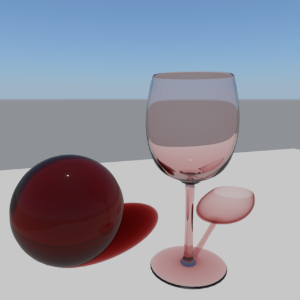
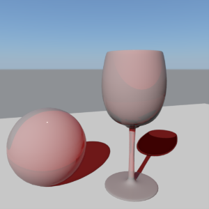
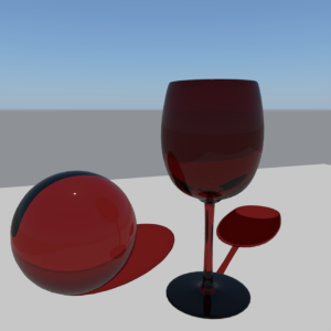
| In the following example refraction fog has been applied to give the illusion of volume for two 'glass' objects. For the solid glass ball on the left, 'Distance' is 1.0, 'Use End Color' is true, 'End Color' is (0.53,0.1,0.1). The 'Refraction Weight' and 'Color' are both set to 1.0. It is recommended that for this effect to work properly, 'Refraction Weight' and 'Color' should always be set to 1.0. A small amount of reflection has also been applied. The glass and shadows appear to have a nice, 'solid' tint to them. | This example has no fogging, but instead we rely on the (0.53, 0.1, 0.1) tint being applied only to the 'Refraction Color'. See how it doesn't look like glass anymore and the illusion of volume has gone? One of the reasons it has started to look more opaque is due to energy conservation kicking in, revealing diffuse lighting. | The example now tries to improve things by knocking out the diffuse contribution ('Diffuse Color' and 'Weight' set to 0.0), but it still doesn't look as realistic as the fall-off effect and is too dark. See the shadows on the floor? The illusion of volume is still not there. |
Ambient Occlusion
Ambient Occlusion (AO) is a subtle, cheap technique that is typically used in place of Global Illumination (GI). When enabled it gives the impression of soft shadows around geometric detail, which can make objects look more natural and 'present' in the scene. Without GI or AO, objects can look like they are 'floating' and not really part of the environment, because of the lack of subtle lighting interaction between objects. Redshift supports two modes for combining the AO result with the rest of the shader, the default being an additive effect that treats the AO result as if it was a diffuse 'indirect light' color that gets added to the lighting results. The second mode is a multiplicative effect that tints the final shader result with the AO result, which can be useful if you want to accentuate the occlusion 'shadows' without adding extra ambient 'light'.
For a more thorough explanation of AO in general, see the Ambient Occlusion shader documentation.
Enable
This enables the ambient occlusion effect.
Combine Mode
This controls how the ambient occlusion result is combined with the rest of the shader results. The options are as follows:
- Add – add to the diffuse indirect lighting contribution
- Multiply – multiply with the final shader result
NOTE: 'Add' mode is best used as a cheap replacement for GI, whereas 'Multiply' mode should be used in conjunction with GI.
Apply To Incandescence
When in 'Multiply' combine mode, AO should be only applied to direct and indirect lighting to be realistic. Enabling this option allows you to apply the multiplied AO to the incandescent color of the material too.
Apply Camera Exposure Compensation
When in 'Add' mode, this adjusts the ambient occlusion result so that camera exposure compensation is factored in. This is useful when you are using lights with physically correct brightness in your scene and photographic exposure is required. If this is not enabled, your ambient occlusion result might appear too dim.
Samples
This controls the number of rays shot. The more samples there are, the smoother the result. Using 32 to 64 samples produces generally good results.
Max Distance
This controls the maximum distance of each ray. The larger the distance, the more likely the ray will hit something and contribute to the overall occlusion effect. Setting a length of 0.0 will use the maximum ray distance of the scene.
Spread
Ambient occlusion works by shooting a number of rays for each pixel. These rays are shot in a hemispherical fashion which produces a smoothly spread out result. The spread parameter makes the rays more concentrated around the pixel's normal which allows the AO effect to be 'tightened'. The lower this value is, the tighter the AO effect.
Falloff
This allows you to control the tightness of the transition between occluded and un-occluded areas, with values less than 1.0 biasing towards un-occluded and values greater than 1.0 toward occluded.
Invert Normal
This option allows you to reverse the occlusion effect, whereby open corners will now receive the occlusion.
Shadow Color
This is the color tint when completely occluded.
Ambient Color
This is the color tint when completely un-occluded.
Ambient Occlusion in Detail
|
|
|
|
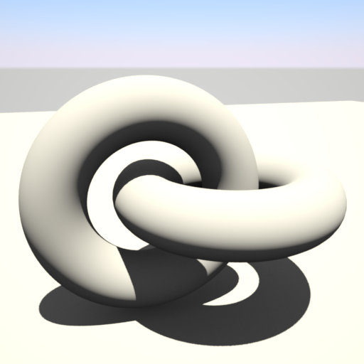
This example shows a scene that is lit by the sun, with a photographic exposure camera shader applied. GI has been disabled. See how with no GI, the shadows are solid black, with no subtle detail. |
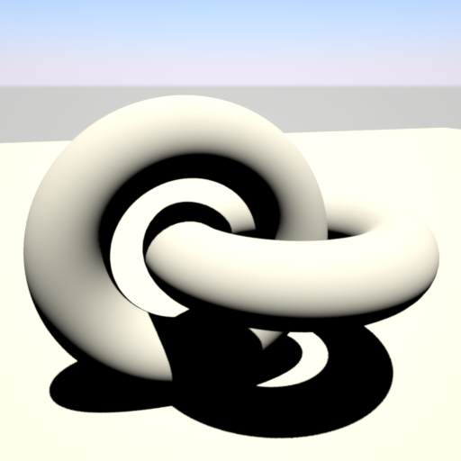
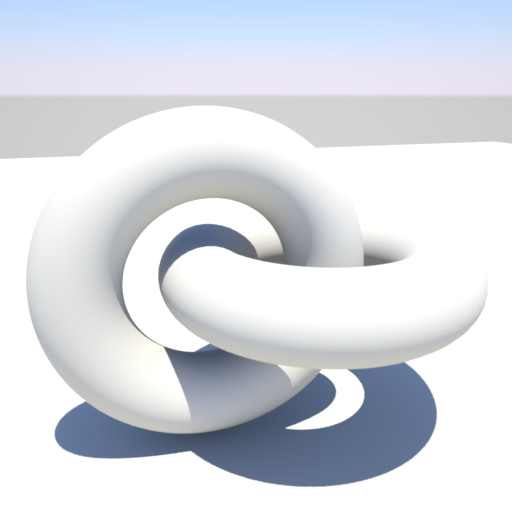
This example shows the AO effect in 'Add' combine mode, with AO set for both the floor and the rings. The material has a 'Max Distance' of 10000.0, 256 'Samples', an 'Ambient Color' of (0.2,0.2,0.2) and a 'Shadow Color' of (0.0,0.0,0.0). You can clearly see the ambient 'indirect light' introduced, with subtle occlusion 'shadow' details. Also notice how the overall lighting is a bit brighter than the previous example. |
|
|
|
|
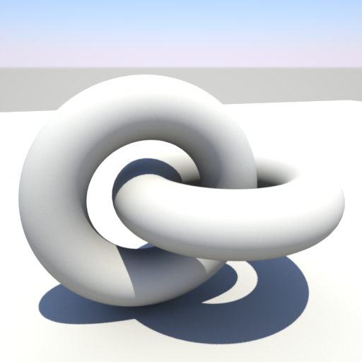
This example shows the same scene, but with GI now enabled and AO disabled. |
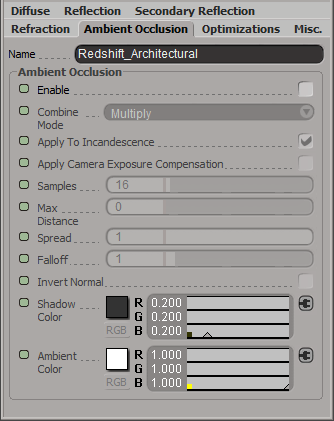
Now we re-enable AO, to accentuate the occlusion 'shadows', but this time in 'Multiply' combine mode because we don't want to add extra brightness. The color values used are the default for 'Multiply' mode: 'Shadow Color' of (0.2, 0.2, 0.2) and an 'Ambient Color' of (1.0, 1.0, 1.0). |
Optimizations
While global optimization defaults are generally adequate for a whole scene, you can control some elements of per material performance with these settings.
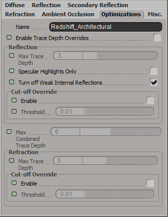
Enable Trace Depth Overrides
This enables the Max Reflection/Refraction Trace Depth parameters.
When not enabled, the global trace depths will be used.
Reflection
Trace Depth
This parameter controls the trace depth for rays shot from the material. If the reflected results are not very defined (they are blurry because of the glossiness parameter or have a low weight), then multiple reflection bounces can be a waste of rendering time. This parameter allows the user to reduce the trace depth and speed up rendering.
Specular Highlights Only
When this parameter is enabled, only reflections from lights will be computed. I.e. no other object in the scene will show through the reflections. This is faster than computing full reflections and in some cases it might be desirable too (if reflections look "too busy"). However, it will also introduce visual inconsistencies especially if other materials in the same scene are configured to use full reflections. In these cases, this parameter should be enabled.
Turn off Weak Internal Reflections
This is a simple, but important performance optimization to prevent rays being 'wasted' inside objects that are both reflective and refractive. Normally, two rays would be spawned for every surface hit inside the object, one for reflection and one for refraction. If you had a sphere, for example, you would have rays bouncing about, trapped inside the sphere until their max trace depth is reached, potentially adding very little to the overall visual quality of the sphere if the reflected amount is 'weak'.
Having this option enabled turns off reflected rays inside the object. Note that this option does not affect refractive rays that are reflected due to Total Internal Reflection. One caveat of using this option is that internal specular reflections will be lost, which is not realistic, but often acceptable. This is enabled by default.
Cut-off Override Enable
This enabled the ability to sepcify a custom reflection cut-off override.
Cut-off Override Threshold
When the reflected results are very dark (because of low "Weight" or "Color" values) they contribute very little to the final image. This parameter defines what is considered "very dark" at which point no more reflection rays will be shot - which will speed up rendering. Scenes containing very strong lights might need this parameter set to very low values such as 0.0001 in order to avoid early termination of tracing which can produce a grain-like effect.
Refraction
Trace Depth
This parameter controls the trace depth for rays shot from the material. If the refracted results are not very defined (they are blurry because of the glossiness parameter or have a low weight), then multiple refraction bounces can be a waste of rendering time. This parameter allows the user to reduce the trace depth and speed up rendering.
Cut-off Override Enable
This enabled the ability to sepcify a custom refraction cut-off override.
Cut-off Override Threshold
When the refracted results are very dark (because of low "Weight" or "Color" values) they contribute very little to the final image. This parameter defines what is considered "very dark" at which point no more refraction rays will be shot - which will speed up rendering. Scenes containing very strong lights might need this parameter set to very low values such as 0.0001 in order to avoid early termination of tracing which can produce a grain-like effect.
Weak Internal Reflection in Detail
|
|
|
|
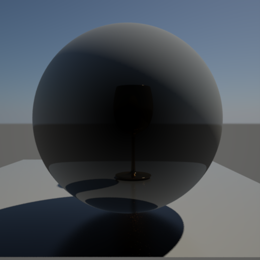
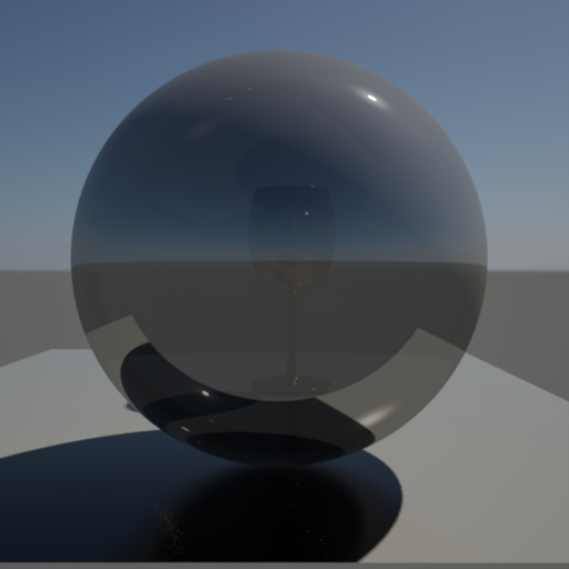
In this example, the sphere is partially reflective and refractive (both weights are 0.3), with a goblet behind the sphere. 'Turn Off Weak Internal Reflections' has NOT been enabled, and you can see some reflected highlights inside the sphere from the multiple bounces. |
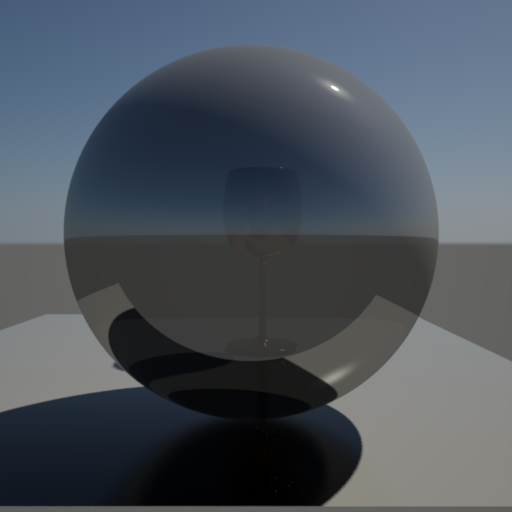
In this example, 'Turn Off Internal Reflections' is now checked. You can see that some internal reflection detail has been lost, particularly the 'hot' details, but it looks almost the same and, more importantly, renders significantly faster. |
Miscellaneous
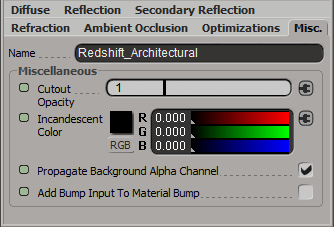
Cutout Opacity
When textured this means that at values of 0.5 and above, the material will be treated as normal, but below that threshold, the material becomes completely transparent. This is useful for cutting out holes in otherwise solid polygons geometry.
Incandescent Color
This color is merely added to the final shaded color result. It is used to make an object glow.
Incandescent Scale
Sets the scale of the incandescent color.
Propogate Background Alpha Channel
This allows blending between the current 'background' alpha channel value in the scene with the approximated opacity of the material, otherwise the alpha channel is replaced with 1.0.
Add Bump Input To Material Bump
This adds the bump map specified below to the shaders material level bump map.
Bump Input
Connect your shader bump map here.