Table Of Contents
Introduction
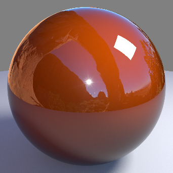
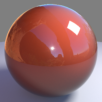
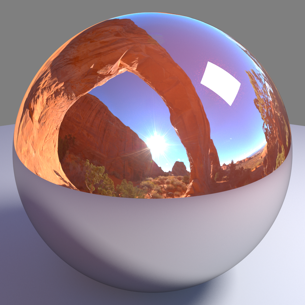
The car paint material shader simulates the physical properties of most types of car paint. For computer graphics, car paint is generally modeled as three separate layers:
- Base pigment layer, with a diffuse color that can change depending on the viewing angle.
- Metallic, reflective flakes that are embedded within the pigment layer.
- A 'binder', which is a shiny/waxed coating exhibiting very glossy reflection.
The car paint material shader also exhibits a strong Fresnel effect, which can be controlled by the parameters below and helps with the paint's character. As with the Architectural shader, the Fresnel effect determines what the color should be when viewed at grazing angles.
Base Layer Diffuse
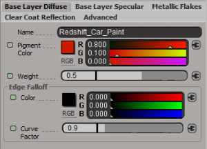
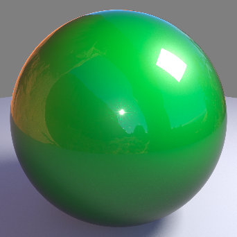
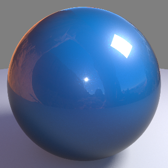
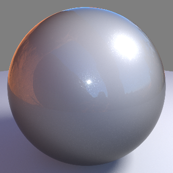
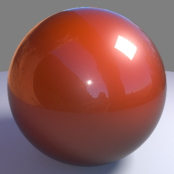
Pigment Color
This is the overall color of the paint pigment.
If the pigment color is set to black you will not see any metallic flakes because the metallic flake color takes on the color of this base layer pigment color.
|
|
|
|
|
| Pigment Color: Red | Green | Blue | Grey |

Weight
This is a multiplier that scales the amount of diffuse lighting that can be received. For correct energy conservation, this should be less than 1.
|
|
|
|
|
|
| Weight: 0.0 | 0.25 | 0.5 | 0.75 | 1.0 |

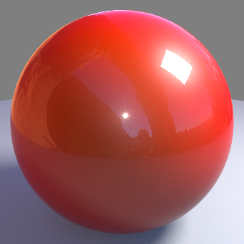
Edge Falloff Color
This is the color that is seen at glancing angles, due to the Fresnel effect. Typically, very metallic paints have an edge color of black.
|
|
|
|
|
|
| Falloff Color: Black | Red | Green | Cyan | Blue |
Edge Falloff Curve Factor
This controls the curve fall-off for the edge tint. The smaller the value, the 'tighter' the transition from the pigment color to the edge color, with a value of 0.0 meaning no edge color.
|
|
|
|
|
|
| Falloff Curve Factor: 0.5 | 0.9 | 1.2 | 2.0 | 3.0 |
Base Layer Specular
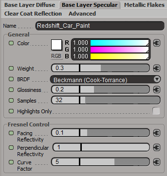
General
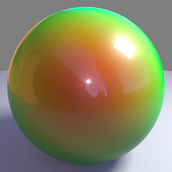
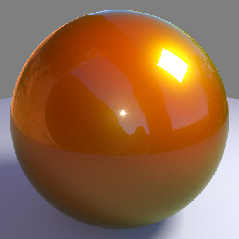
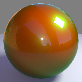
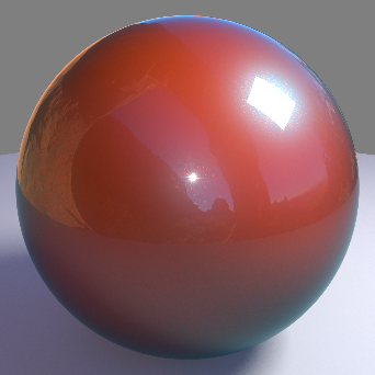
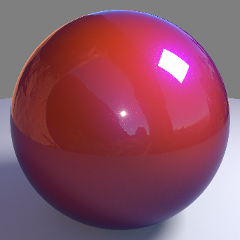
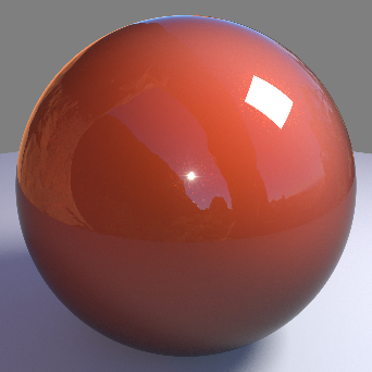
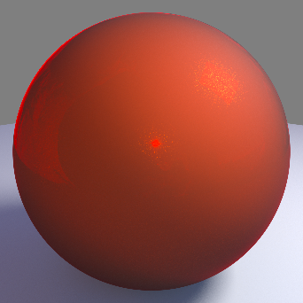
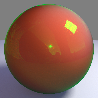
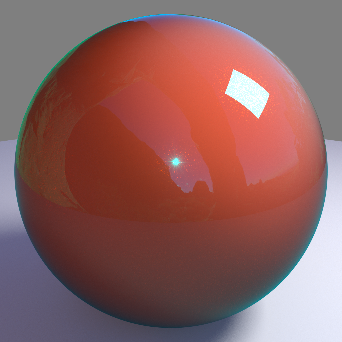
Color
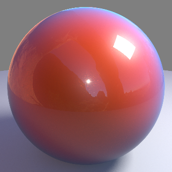
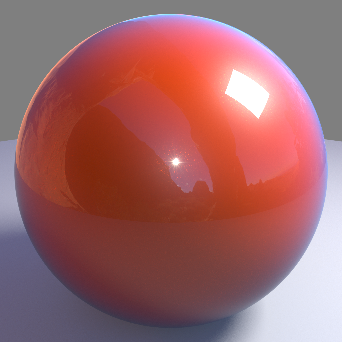
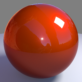
This is the color of the specular reflection for the pigment layer. For a more realistic result, this color should be close to the pigment color.
In the examples below note the base layer specular reflection changing separate from the glossy white clear coat reflection:
|
|
|
|
|
|
| Color: Red | Yellow | Green | Cyan | Blue |
Weight
This is a multiplier that scales the amount of specular reflection that can be received. For correct energy conservation, this should be less than 1.
In the examples below note the base layer specular reflection changing separate from the glossy white clear coat reflection:
|
|
|
|
|
|
| Weight: 0.0 | 0.25 | 0.5 | 0.75 | 1.0 |


BRDF
Allows you to choose the technique for simulating physically correct rough reflections. Beckmann is generally considered the standard for a good range of materials, but GGX has a wide specular tail, which is good for chrome materials.
- Ashikhmin-Shirley (legacy)
- Beckmann (Cook-Torrance)
- GGX
- Ashikhmin-Shirley
The legacy BRDF option uses a non-linear looking glossiness fall-off and exists to maintain compatibility with 1.0 materials.
In the examples below note the base layer specular reflection changing separate from the glossy white clear coat reflection:
|
|
|
|
| BRDF: Ashikhmin-Shirley | Beckmann | GGX |
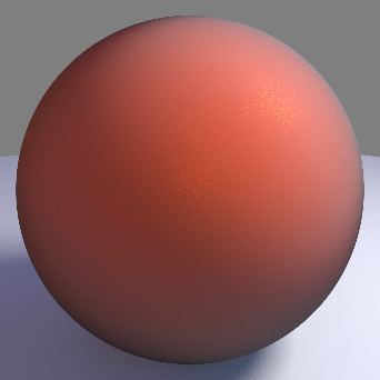
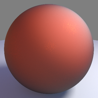
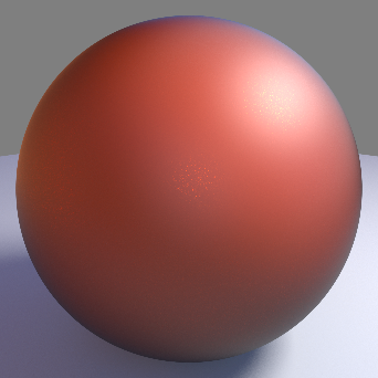
Glossiness
High glossiness means sharp reflections. Lower numbers will make the reflections blurrier. Paint pigment typically has a low glossiness.
In the examples below note the base layer specular reflection changing separate from the glossy white clear coat reflection:
|
|
|
|
|
|
| Glossiness: 0.0 | 0.25 | 0.5 | 0.75 | 1.0 |

Samples
This controls the number of ray traced samples required for the glossiness. A value of 0.0 means 1 sample, with perfect specular reflection. The 'rougher' the gloss, the more samples you will need to get rid of noise. Also be aware that the more samples you use, the longer it will take to render.
Highlights Only
This optimization option will disable indirect reflection ray tracing of the environment and just capture specular reflections from lights.
Fresnel Control
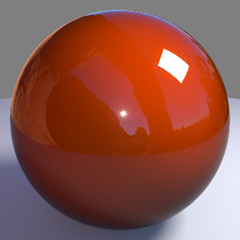
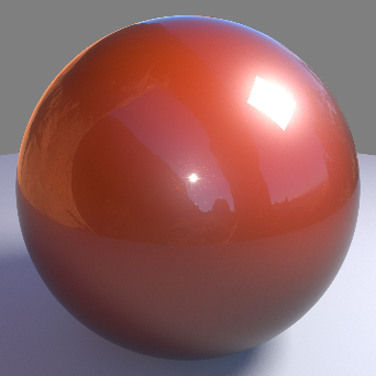
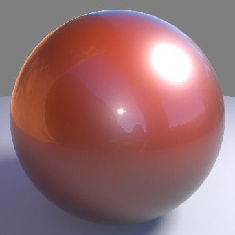
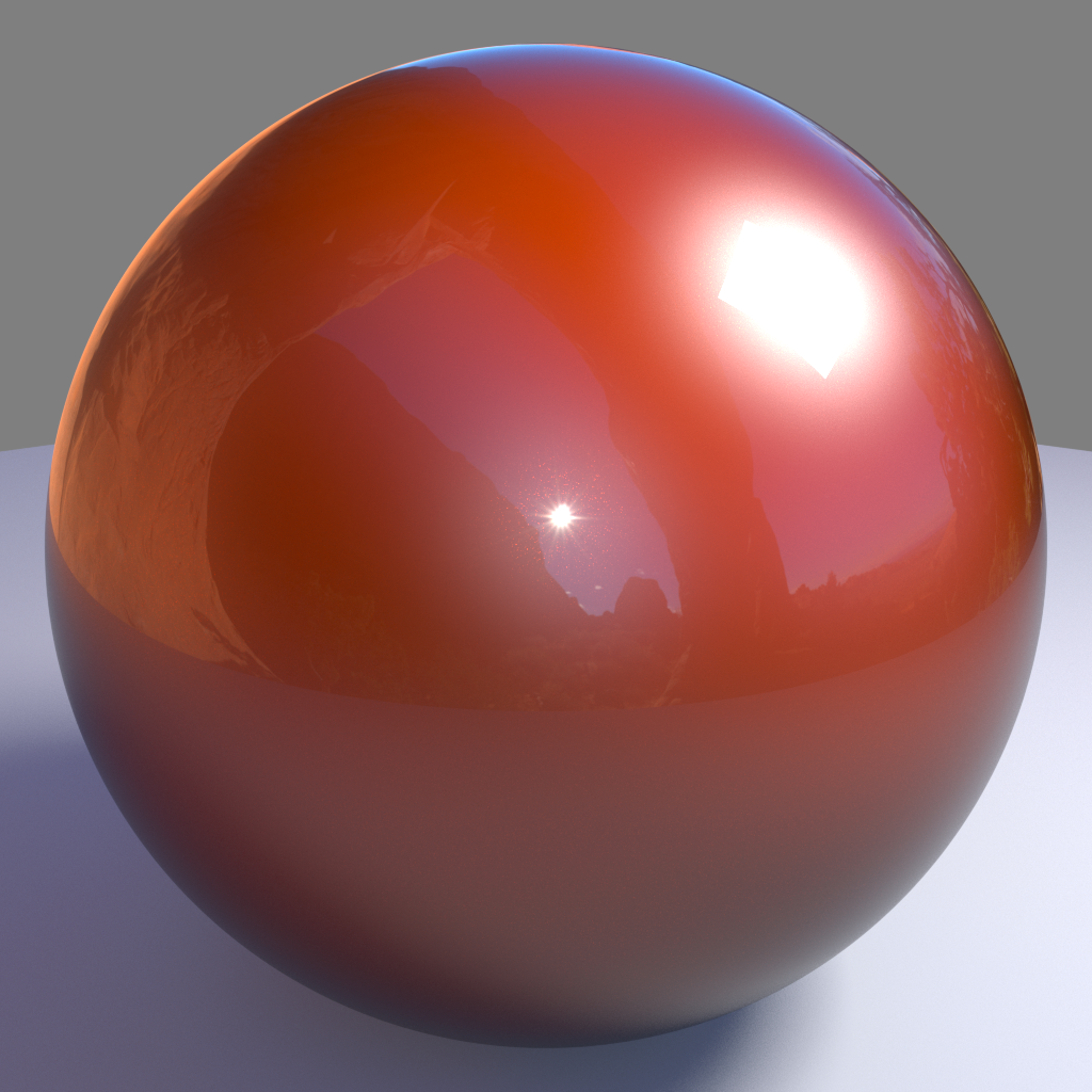
Facing Reflectivity
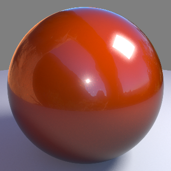
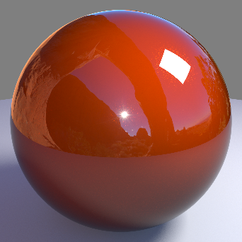
This controls the strength of reflections when viewed head on, at a 0 degree angle from the surface. The values range between 0.0 and 1.0. Typically, metals will have a high setting, with a perfect mirror being 1.0. Most materials with reflective coats, however, should have relatively low values, which is why the default is 0.1.
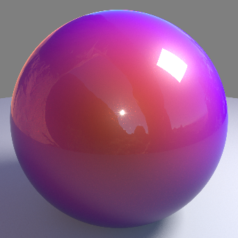
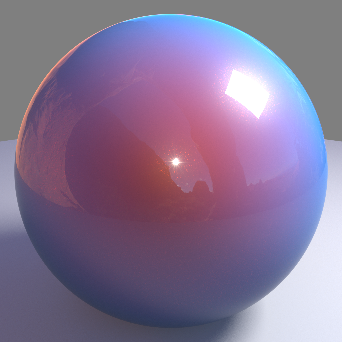
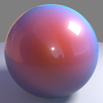
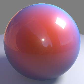
In the examples below the settings have been tweaked to better show the effect made by facing reflectivity. The metallic flakes and clear coat refleciton have been disabled leaving only the base layer specular reflection. Base layer specular weight is set to 0.7, glossiness is set to 1.0, the curve factor has been set to a value of 0.3, and perpendicular reflectivity has been set to 0. Note how the facing reflectivity value makes reflections stronger when they are facing the camera and remain dim around the edge of the sphere when facing farther away from the camera. The last image on the right illustrates facing reflectivity with perpendicular reflectivity re-enabled at a value of 0.5.
|
|
|
|
|
|
Facing Reflectivity: 0.0 Perpendicular Reflectivity: 0.0 Curve Factor: 0.3 |
0.25 |
1.0 |
1.0 0.5 |
Perpendicular Reflectivity
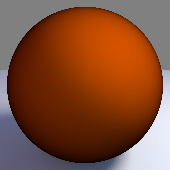
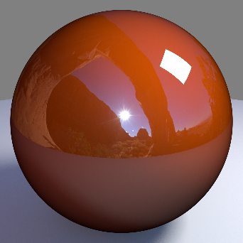
This controls the strength of reflections when viewed at a 90 angle from the surface. In keeping with the Fresnel effect, this should always bet set to 1.0 so that reflections will be stronger when viewed at shallow angles.
If the Facing and Perpendicular values are the same, then the Fresnel effect will be disabled and there will be equal reflection, regardless of viewing angle.
In the examples below the settings have been tweaked to better show the effect made by perpendicular reflectivity. The metallic flakes and clear coat reflection have been disabled leaving only the base layer specular reflection. Base layer specular weight is set to 0.7, glossiness is set to 1.0, the curve factor has been set to a value of 1.0, and facing reflectivity has been set to 0. Note how the perpendicular reflectivity value makes reflections stronger when they are facing away from the camera around the edges of the sphere and remain dim where the faces are facing more towards the camera in the center. The last image on the right illustrates perpendicular reflectivity with facing reflectivity re-enabled at a value of 0.5.
|
|
|
|
|
|
Perpendicular Reflectivity: 0.0 Facing Reflectivity: 0.0 Curve Factor: 1.0 |
0.25 |
1.0 |
1.0 0.5 |

Curve Factor
This controls how the facing and perpendicular reflected strength transitions between one and the other. Higher values produce a 'tighter' transition.
In the examples below the settings have been tweaked to better show the effect made by curve factor. The metallic flakes and clear coat refleciton have been disabled leaving only the base layer specular reflection, base layer specular weight is set to 0.7 and glossiness is set to 1.0. Note the different transitions achieved below between facing and perpendicular reflectivity when adjusting the curve factor, as the value is increased the reflection intensity is tightened more closely around the edges of the sphere.
|
|
|
|
|
|
|
Curve Factor: 0.1 Facing Reflectivity: 0.1 Perpendicular Reflectivity: 1.0 |
0.5 |
1.0 |
2.5 |
5.0 |
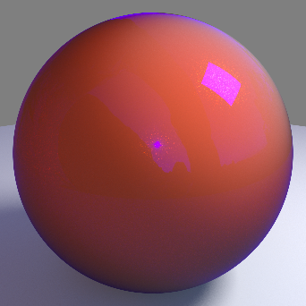
Metallic Flakes
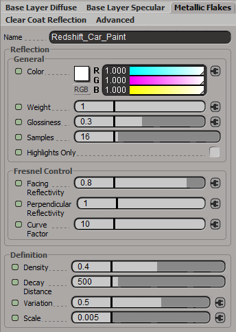
Reflection General
Color
This is the color of the flakes. Since the flakes are embedded inside the pigment layer, they will also take on the color of the pigment.
|
|
|
|
|
|
Metallic flake color examples |
|


Weight
This is a multiplier that scales the amount of reflection the flakes can receive. For correct energy conservation, this should be less than 1.
|
|
|
|
|
| Weight: 0.0 | 0.25 | 0.5 | 1.0 |


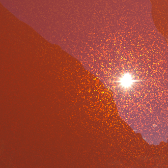
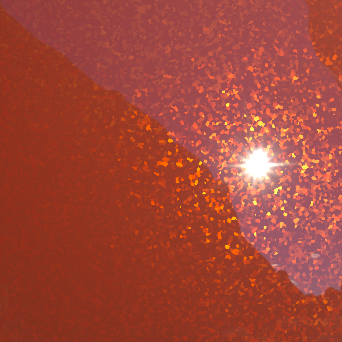
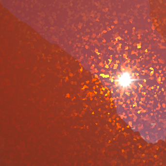
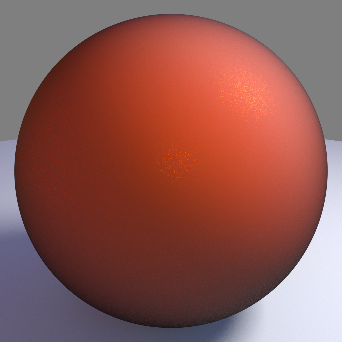
Glossiness
High glossiness means sharp reflections. Lower numbers will make the reflections blurrier. Metals typically have low glossiness.
Below are examples of different flake glossinesss values. Note how the higher the value the tighter and more pronounced the flake reflection, where as lower values spreads the flake reflection out across the surface more:
|
|
|
|
|
| Glossiness: 0.0 | 0.5 | 0.75 | 1.0 |


Samples
This controls the number of ray traced samples required for the glossiness. A value of 0.0 means 1 sample, with perfect specular reflection. The 'rougher' the coat, the more samples you will need to get rid of noise. Also be aware that the more samples you use, the longer it will take to render.
Highlights Only
This optimization option will disable indirect reflection ray tracing of the environment and just capture specular reflections from lights for the flakes.
Fresnel Reflection Control
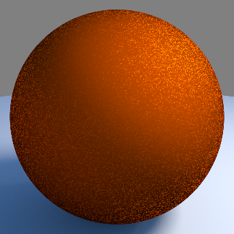
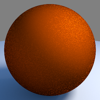
Facing Reflectivity
This controls the strength of reflections when viewed head on, at a 0 degree angle from the surface. The values range between 0.0 and 1.0. Typically, metals will have a high setting, with a perfect mirror being 1.0. Most materials with reflective coats, however, should have relatively low values, which is why the default is 0.1.
In the examples below the settings have been tweaked to better show the effect made by facing reflectivity on the metallic flakes. The base layer and clear coat refleciton have been disabled leaving only the metallic flakes reflection. Metallic flakes weight is set to 10, glossiness is set to 0.5, density is set to 0.5, scale is set to 0.05, the curve factor has been set to a value of 0.3, and perpendicular reflectivity has been set to 0. Note how the facing reflectivity value makes reflections stronger when they are facing the camera and remain dim around the edge of the sphere when facing farther away from the camera. The last image on the right illustrates facing reflectivity with perpendicular reflectivity re-enabled at a value of 0.5.
|
|
|
|
|
|
Facing Reflectivity: 0.0 Perpendicular Reflectivity: 0.0 Curve Factor: 0.3 |
0.25 |
1.0 |
1.0 0.5 |


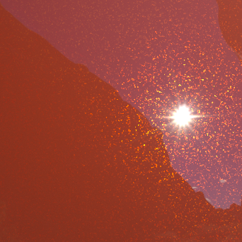
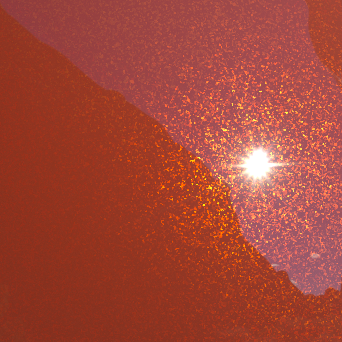
Perpendicular Reflectivity
This controls the strength of reflections when viewed at a 90 angle from the surface. In keeping with the Fresnel effect, this should always bet set to 1.0 so that reflections will be stronger when viewed at shallow angles.
If the Facing and Perpendicular values are the same, then the Fresnel effect will be disabled and there will be equal reflection, regardless of viewing angle.
In the examples below the settings have been tweaked to better show the effect made by perpendicular reflectivity on the metallic flakes. The base layer and clear coat refleciton have been disabled leaving only the metallic flakes reflection. Metallic flakes weight is set to 10, glossiness is set to 0.5, density is set to 0.5, scale is set to 0.05, the curve factor has been set to a value of 1.0, and facing reflectivity has been set to 0. Note how the perpendicular reflectivity value makes reflections stronger when they are facing away from the camera around the edges of the sphere and remain dim where the faces are facing more towards the camera in the center. The last image on the right illustrates perpendicular reflectivity with facing reflectivity re-enabled at a value of 0.5.
|
|
|
|
|
|
Perpendicular Reflectivity: 0.0 Facing Reflectivity: 0.0 Curve Factor: 1.0 |
0.25 |
1.0 |
1.0 0.5 |

Curve Factor
This controls how the facing and perpendicular reflected strength transitions between one and the other. Higher values produce a 'tighter' transition.
In the examples below the settings have been tweaked to better show the effect made by curve factor on the metallic flakes. Metallic flakes weight is set to 3.0, glossiness is set to 0.5, density is set to 0.5, scale is set to 0.05, and variation is set to 10. Additionally the base layer and clear coat refleciton have been disabled leaving only the metallic flakes reflection. Note the different transitions achieved between facing and perpendicular reflectivity when adjusting the curve factor, as the value is increased the reflection intensity is tightened more closely around the edges of the sphere.
|
|
|
|
|
|
|
Curve Factor: 0.1 Facing Reflectivity: 0.1 Perpendicular Reflectivity: 1.0 |
0.5 |
1.0 |
2.5 |
5.0 |


Definition
Density
This controls the density of the flakes, with lower values meaning sparser flakes.
|
|
|
|
|
|
| Density: 0.0 | 0.25 | 0.5 | 0.75 | 1.0 |


Decay Distance
This controls the distance at which the visible flake effect will decay to nothing. In reality on a very sunny day, flakes can be seen for several meters, so this should be tuned to match the lighting. A value of 0.0 means the flakes will always be visible.
It is important to use this option, because as with any 'noisy' effect, once it becomes sub-pixel it will look like an undesirable artifact.
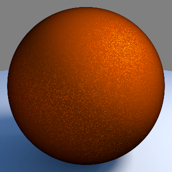
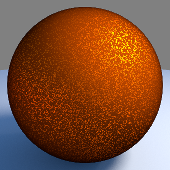
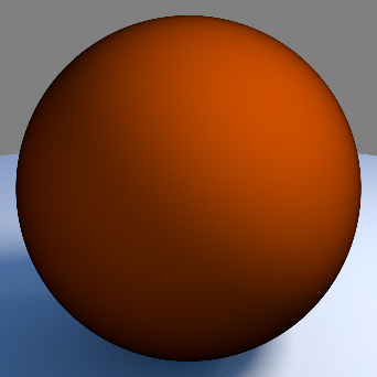
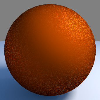
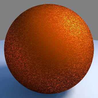
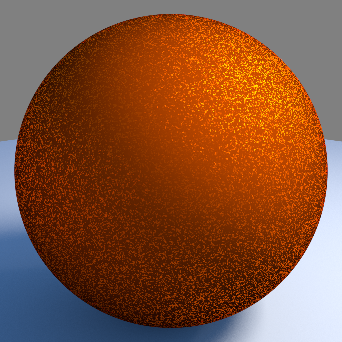
Variation
This controls the flake orientation perturbation amount, with respect to the surface. A value of 0.0 means the flakes will have no perturbation and, essentially, have the same normal as the surface. Higher values yield a more noticeable flake effect.
Below you can see examples of the effect flake variation has on the visibility of flakes. These examples all have the same density and other reflection settings. This parameter is great for when you want to make the flakes more pronounced without changing other reflection attributes.
|
|
|
|
|
|
| Variation: 0.0 | 0.25 | 0.5 | 0.75 | 1.0 |


Scale
This controls the size of the flakes. Usually very small values should be used, around 0.005 to look realistic.
|
|
|
|
| Scale: 0.005 | 0.010 | 0.015 |
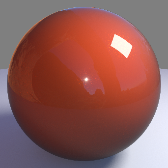
Clear Coat Reflection
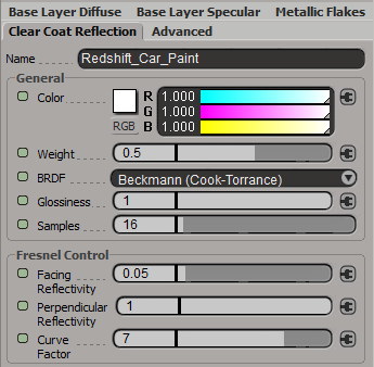
General
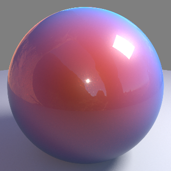
Color
This is the color of the reflection coat layer.
|
|
|
|
|
|
|
|
|
Different clear coat colors |
|
|
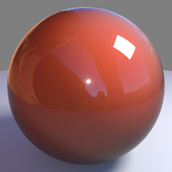
Weight
This is a multiplier that scales the amount of specular reflection that can be received. For correct energy conservation, this should be less than 1.
|
|
|
|
|
| Weight: 0.0 | 0.25 | 0.5 | 1.0 |
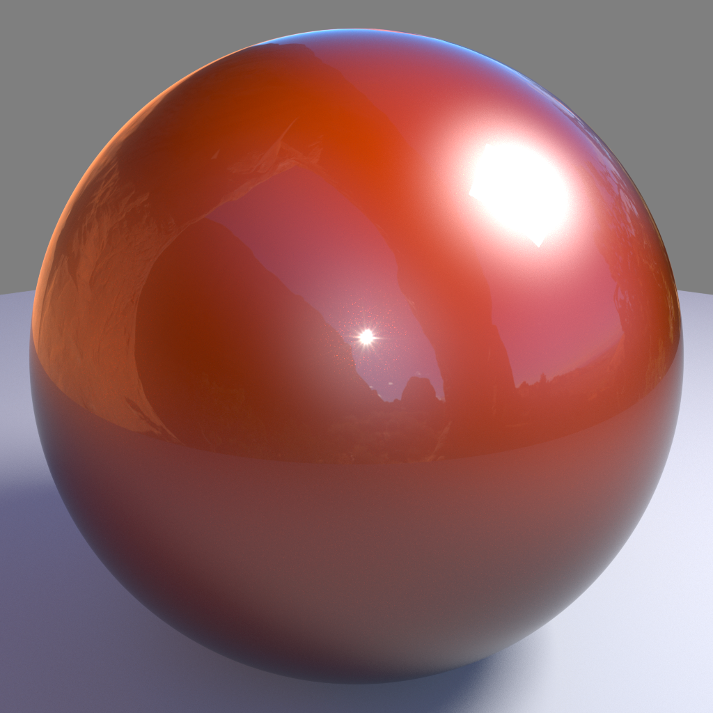
BRDF
Allows you to choose the technique for simulating physically correct rough reflections. Beckmann is generally considered the standard for a good range of materials, but GGX has a wide specular tail, which is good for chrome materials.
- Ashikhmin-Shirley (legacy)
- Beckmann (Cook-Torrance)
- GGX
- Ashikhmin-Shirley
The legacy BRDF option uses a non-linear looking glossiness fall-off and exists to maintain compatibility with 1.0 materials.
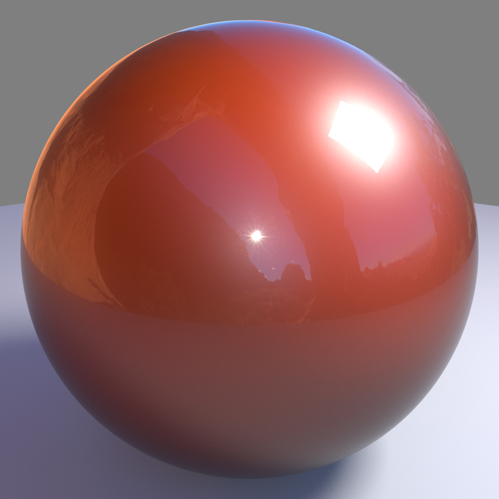
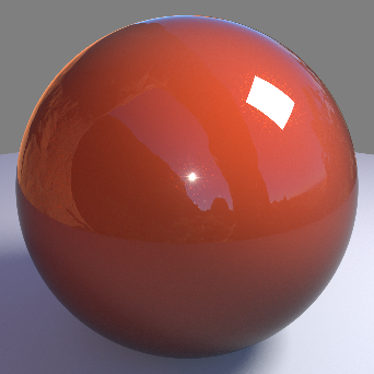
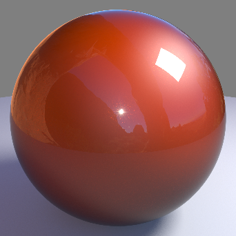
Glossiness
High glossiness means sharp reflections. Lower numbers will make the reflections blurrier.
|
|
|
|
|
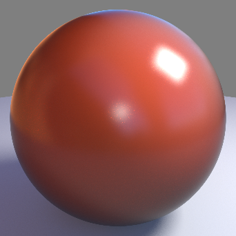
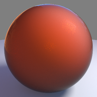
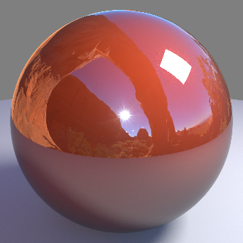
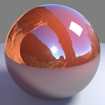
|
| Glossiness: 0.0 | 0.25 | 0.5 | 0.75 | 1.0 |

Samples
This controls the number of ray traced samples required for the glossiness. A value of 0.0 means 1 sample, with perfect specular reflection. The 'rougher' the gloss, the more samples you will need to get rid of noise. Also be aware that the more samples you use, the longer it will take to render.
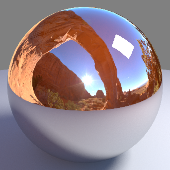
Fresnel Control
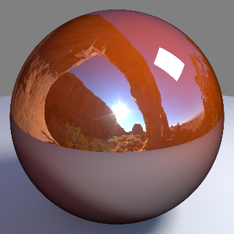
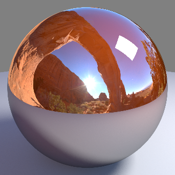
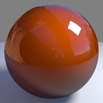
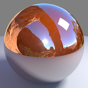
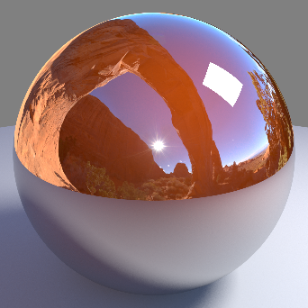
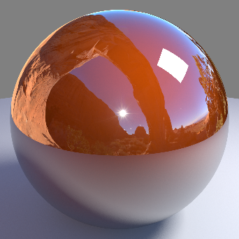
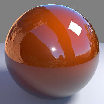
Facing Reflectivity
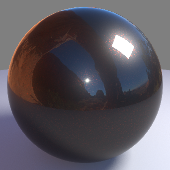
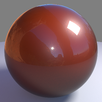
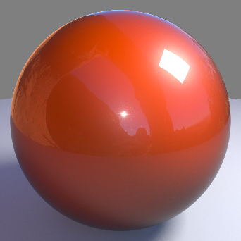
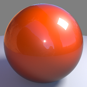
This controls the strength of reflections when viewed head on, at a 0 degree angle from the surface. The values range between 0.0 and 1.0. Typically, metals will have a high setting, with a perfect mirror being 1.0. Most materials with reflective coats, however, should have relatively low values, which is why the default is 0.1.
|
|
|
|
|
|
| Facing reflectivity: 0.0 | 0.25 | 0.5 | 0.75 | 1.0 |

Perpendicular Reflectivity
This controls the strength of reflections when viewed at a 90 angle from the surface. In keeping with the Fresnel effect, this should always bet set to 1.0 so that reflections will be stronger when viewed at shallow angles.
If the Facing and Perpendicular values are the same, then the Fresnel effect will be disabled and there will be equal reflection, regardless of viewing angle.
|
|
|
|
| Perpendicular reflectivity: 0.0 | 0.5 | 1.0 |

Curve Factor
This controls how the facing and perpendicular reflected strength transitions between one and the other. Higher values produce a 'tighter' transition.
|
|
|
|
|
|
| Curve factor: 0.0 | 25 | 50 | 75 | 100 |


Advanced
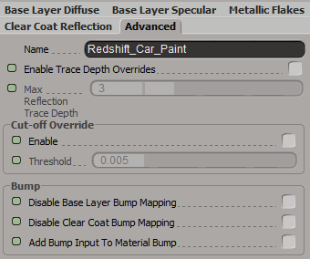
Enable Trace Depth Overrides
This enables the Max Reflection Trace Depth parameter. When not enabled, the global trace depth will be used.
When enabled you can exceed the global reflection trace depth for the car paint shader.
Max Reflection Trace Depth
This parameter controls the trace depth for reflection rays shot from this material. If the reflections of a material are not very defined (meaning: they are blurry because of the glossiness parameter or have a low weight), then multiple reflection bounces can be a waste of rendering time. This parameter allows the user to reduce the trace depth and speed up rendering.
Cut-off Override
Enable
This parameter allows you to override the global cut-off setting for reflections.
Threshold
When the reflections of a material are very dark (because of low "Weight" or "Color" values) they contribute very little to the final image. This parameter defines what is considered "very dark" at which point no more reflection rays will be shot - which will speed up rendering. Scenes containing very strong lights might need this parameter set to very low values such as 0.0001 in order to avoid early termination of tracing which can produce a grain-like effect.
Bump
Disable Base Layer Bump Mapping
This option allows you to switch to using the default un-bumped surface normals for direct and indirect base layer lighting calculations.
Disable Clear Coat Bump Mapping
This option allows you to switch to using the default un-bumped surface normals for direct and indirect clear coat reflection lighting calculations.
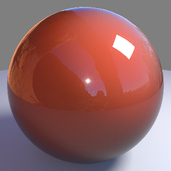
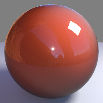
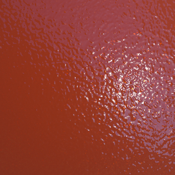
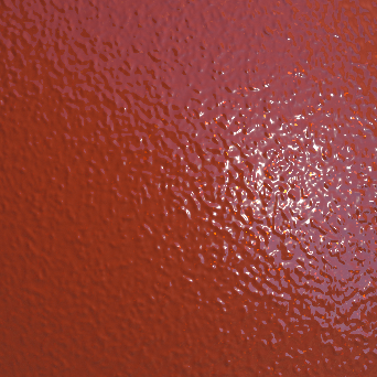
Below is an example of the many different ways you can isolate bump mapping on the car paint shader. Note how the specular breakup changes from the bump mapping depending on which layers are affected. These options allow you to create complex layered looks all within a single car paint shader.
|
|
|
|
|
| Bump Map off | Bump Map on base | Bump Map on clear coat | Bump Map on base and clear coat |


Add Bump Input To Material Bump
Adds the local car paint bump to the material bump.
Bump Map
Connect your car paint bump map here.