---
title: "Working with Materials in Maxon Redshift for Architects"
url: "https://help.maxon.net/rva/en-us/Content/html/Materials.html"
section_path: "Materials"
description: "Redshift for Architects comes with many professional materials that can be assigned directly to objects in your project. Here you'll find all the information you need on how to access, edit, and assign materials."
---
# Working with Materials
Materials give objects a natural-looking surface. The properties of materials include, for example, the surface color, transparency, and gloss behavior of a surface. The material system uses a physics-based node system that automatically replicates the natural and realistic behavior of real materials such as metal, glass, or wood.
**Quick Navigation**
- Your Architectural Materials in Maxon Redshift
- Maxon Redshift Material Overview
- Searching for the right Material
- Applying a Material
- Editing a Material
- Creating a New Material
- The Material Projection
- The Material Assignments
---
## Your Architectural Materials in Maxon Redshift
When opening the Maxon Redshift viewer, all the already assigned materials from your architectural application are converted to Maxon Redshift materials and stored in the viewer as read-only. Therefore, it is not possible to edit the converted architectural material directly within Maxon Redshift. In any case, it remains exactly as it was defined in your architectural application.
However, these architectural materials can be unlocked for editing by creating a copy within Maxon Redshift. In this case, the existing material on the corresponding objects is automatically overwritten by its copy. Further information about **Material Editing** can be found in this section.
A second option is to use a new Maxon Redshift material from the [Library Browser](https://help.maxon.net/rva/en-us/Content/html/Library_Browser.html.md) and then overwrite the existing material from your architectural application with it. The following sections of this page describe how to access new materials from the [**Library Browser**](https://help.maxon.net/rva/en-us/Content/html/Library_Browser.html.md) and assign them to objects.\
In both cases, however, the overwriting material newly used on the object can also be deleted again. The originally assigned material will then reappear.
In addition, the following conditions apply:
- All objects with the same material will automatically get the new mapping. If there are multiple objects with the same material or texture assigned in your architectural application, upon overriding one of them in the Maxon Redshift viewer, all the other models will get the new material in the Maxon Redshift viewer as well.
- The Redshift materials are not transferred back to your architectural application. It means, that if you assigned a green color to a wall in your architectural tool and then override it with a red material in Maxon Redshift, the visual representation in your architectural app will still show the wall in green.
- In Maxon Redshift, it is not possible to assign different materials to objects if these objects have all been assigned the same material in your architectural application.
- If there are two objects with the same texture coming from your architectural app and a new material mapping in Maxon Redshift, then assigning another texture in your architectural app to one of them will result in this object changing its material in the Maxon Redshift viewer to the imported material or its corresponding override (if it already exists).
- For Revit users: Revit's per-face material assignment is fully supported.
## Maxon Redshift Material Overview
Much of the work has already been done for you, as hundreds of finished materials are already available and can be accessed directly via the **Library** button in the [**Scene**](https://help.maxon.net/rva/en-us/Content/html/Interface.html.md)/*Materials* section (see Figure 1 below, accessible in the [**Stage**](https://help.maxon.net/rva/en-us/Content/html/Interface.html.md) layout).
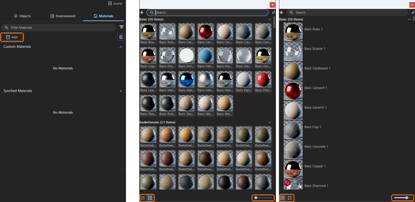
Figure 1A huge database of high-quality materials for all common surfaces can be accessed directly via the **Library** button (see marking on the left). Two different modes and a scaling option are available for listing the available materials (see markings on the right).
In order to find the right material for a project despite this large number of materials, all materials have been organized into different groups and can also be listed individually with a preview image. There is a mode in which these image tiles are given the maximum amount of space and a mode in which the material entries are displayed as a list (see Figure 1). This leaves more space for the descriptive text for each material, which is displayed next to the material preview. In both modes, which can be switched using two icons at the bottom of the browser window, an additional scaling slider is available, which can be used to individually adjust the area for each material preview (see markings in Figure 1).
## Searching for the right Material
In addition to these material selection options, there is also a search field in the header of the browser. All materials have been assigned descriptive names and keywords so that you can easily search for “*metal*”, for example. Logical combinations are often possible, such as “*blue plastic*.”
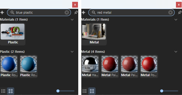
Figure 2A search field at the top allows you to filter materials according to specific terms.
Even more natural search results can be achieved by using **AI**-supported search (**A**rtificial **I**ntelligence). This automatically filters materials based on their appearance. A search for a red material, for example, can also return search results that contain surfaces with a slight purple or orange tint. This gives you a wider selection of materials similar to your search term.
You can activate this AI-supported search by clicking on the star icon to the left of the search field. An information dialog box will appear, confirming that although the AI analyzes the material data and any linked textures, no data will leave your computer (see Figure 3). Processing is therefore carried out exclusively on your local computer (find out more about the options available in the [Asset Library Browser here](https://help.maxon.net/rva/en-us/Content/html/Library_Browser.html.md)).

Figure 3AI search is activated exclusively locally on your hardware.
After this activation, the search results for otherwise identical search terms are much broader, as the following Figure 4 demonstrates. For example, colors in similar materials are also found automatically. In any case, you will always find the most relevant search results at the top of the browser. The greater the deviation of a material from the search term, the further down the list of search results it will appear.
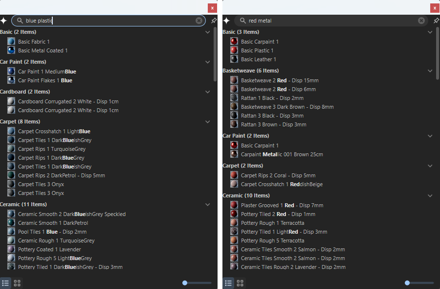
Figure 4AI also finds materials similar to the description.
If you like to work with the *AI Search* by default, you can activate and configure it in the *Preferences* (see Figure 5). As it is capable of using the GPU, you can configure an automatic detection of your Hardware or force it to use the GPU always or never use the GPU (CPU calculations are slower most of the time).\
As the search functionality is also available to filter the other assets in the [Library Browser](https://help.maxon.net/rva/en-us/Content/html/Library_Browser.html.md), *AI Search* can be beneficial not only for materials.
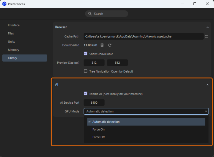
Figure 5AI Search can be configured in the Preferences.
## Applying a Material
In order for objects to inherit the properties of materials, the materials must be assigned. This can be done very easily by dragging and dropping them directly from the *Materials* list onto the corresponding object in the Redshift viewport. The following video demonstrates this process. It also shows that any existing materials on the object will be automatically overwritten.
[Video: Assigning_Materials_01.mp4](https://help.maxon.net/rva/en-us/Content/Resources/Images/Assigning_Materials_01.mp4)
As per-face material assignment is supported for Revit users, be sure to drag the new material directly to the region where is should be applied.
An alternative option is to use the [Material Sampler Tool](https://help.maxon.net/rva/en-us/Content/html/Tool_Material_Sampler.html.md). This allows you to copy materials already assigned in the scene to other objects, as shown in the following video. To do this, click on the object whose material you want to sample with the active **Material Sampler** and then `Shift`-click on the object that you want to apply the sampled material to.
[Video: Material_Sampler_Tool_01.mp4](https://help.maxon.net/rva/en-us/Content/Resources/Images/Material_Sampler_Tool_01.mp4)
Finally, materials that have already been assigned can also be replaced with new materials. To do this, right-click on the corresponding material and then select **Replace Material** from the context menu. The material category of the [Library Browser](https://help.maxon.net/rva/en-us/Content/html/Library_Browser.html.md) will open. Select the desired material by double-clicking on it. This will automatically replace the original material on the corresponding objects in the scene.
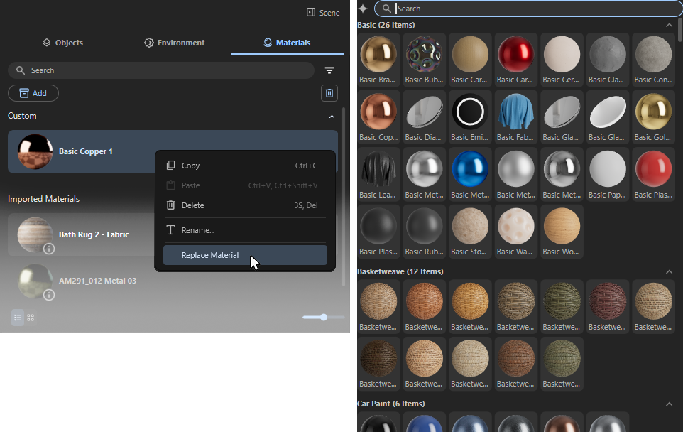
Already applied materials can be replaced by other materials from the **Library**.
> **Important:** Newly assigned materials are automatically applied to all objects that have the material being replaced.\
> For example: All of your window panes have already been assigned the same generic glass material in your architectural software. As soon as you drag one of the optimized glass materials in Maxon Redshift onto one of these window pane objects, all other objects in the scene that used the same generic glass material will automatically adopt the new glass material as well.
> **Important:** **Current Limitation for Revit users:**
>
> Redshift materials projected onto Revit objects via UV mapping are currently being calculated incorrectly in terms of size. Until this issue is resolved, please use Tri-Planar Mapping for Redshift materials instead. There, you can customize the material size as needed.
## Editing a Material
There are several categories of materials to consider: materials imported via synchronization with your architectural tool and *Custom Materials* added to the scene as assets from the [**Library Browser**](https://help.maxon.net/rva/en-us/Content/html/Library_Browser.html.md). The latter can be edited directly, as explained here.\
In addition, you also have the option to create your own custom materials from scratch. A physics-based material system based on the *OpenPBR* standard is available for this purpose. In the following section, you'll learn all about the configuration options available there.
*Imported Materials* are locked for editing in Maxon Redshift for Architects, but we can work around this restriction. To do this, you will find an **Edit** button on *Imported Materials* when you move the mouse pointer over them in the *Materials Manager*. Clicking on it creates a new *Custom Material* that inherits the properties of the *Imported Material* and is automatically assigned to the same objects as an overwrite material. This new material copy can then be edited, for example, in its color properties. If the material copy is removed, for example, by right-clicking on it and selecting **Delete**, the original *Imported Material* is automatically displayed on the objects again. The video below demonstrates this workflow.
[Video: Edit_Imported_Material_01.mp4](https://help.maxon.net/rva/en-us/Content/Resources/Images/Edit_Imported_Material_01.mp4)
### Standard Material Parameters
Even if your desired material cannot be found directly, this is of course not a problem. Simply select a material that looks at least similar and then edit it as desired. Many materials already offer a simple dialog box that allows you to adjust colors and contrasts directly.
Start by selecting a similar material. Pay particular attention to the desired gloss behavior or transparency, as these properties remain unchanged. In most cases, the color, saturation, and brightness of a material can be customized.
#### Color Correction
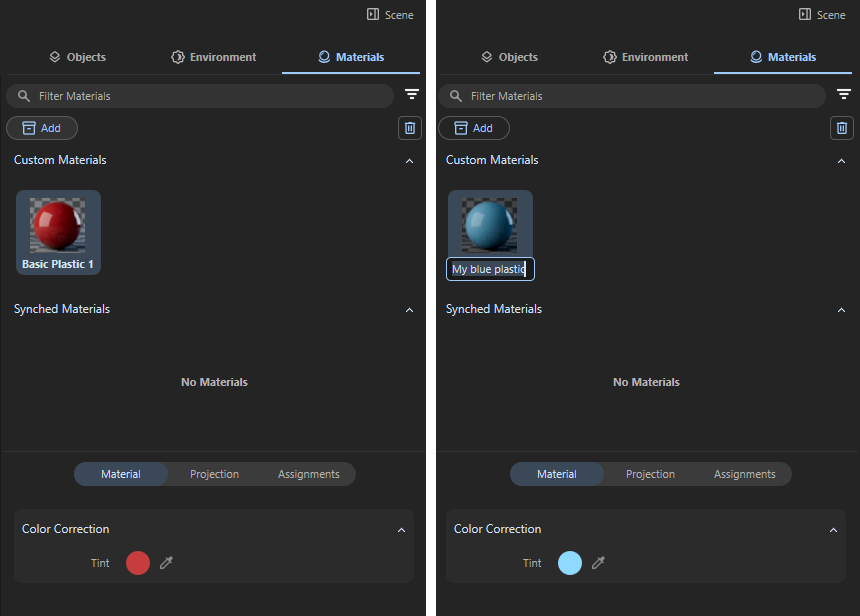
Figure 6Customized versions of found materials can be easily created and saved.
As documented on the left side of Figure 6 you can see, that the chosen plastic material offers a **Tint** input in the lower *Material* category of the *Scene* Manager. Clicking on that circular color field brings up the *Color Chooser* (described [here](https://help.maxon.net/rva/en-us/Content/html/Color_Chooser.html.md) in detail). Alternatively, you can click on the eyedropper next to the color field to select a color value directly from any point on the screen.\
Just adjust the color there to your liking and close the *Color Chooser* afterwards. Then double-click on the material name below the material preview sphere and enter the desired new name for the customized material (see right side of Figure 6). The customized material is now ready for use. The original material is retained and can still be accessed via the **Add** button or by searching for it.
Other materials even offer more settings, such as the one in Figure 7.
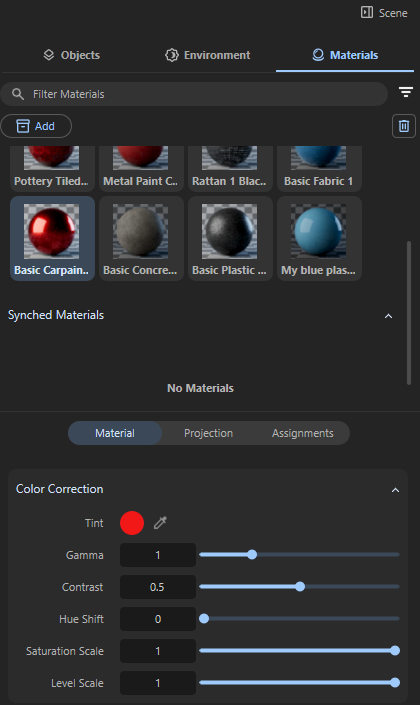
Figure 7Additional controls for individual material adjustments.
In addition to the **Tint** color field already discussed, which allows you to make any changes to the base color, the following settings are also available for some of the materials. Most of these values are settings that are already familiar from image editing. The effect of a setting can depend on the color value that is fed in. For example, the **Gamma** value changes the mid-tones of a color spectrum more than particularly light or dark colors. In the context of our materials, this is nevertheless relevant, as materials can also contain colored patterns (such as wood grain), which can then be adjusted accordingly using these settings:
- **Gamma**: This value refers to a nonlinear adjustment applied to the brightness or luminance of the colors. Its main function is to control how the mid-tones of a spectrum of colors appear without drastically changing the darkest shadows or brightest highlights. In general:
[Video: Mat_Gamma_Ani.mp4](https://help.maxon.net/rva/en-us/Content/Resources/Images/Mat_Gamma_Ani.mp4)
Example of Gamma adjustments for the sofa material.
- **Contrast**: This controls the difference in luminance or color between the lightest and darkest parts of a given color spectrum. Its main function is to adjust how much separation there is between tones, which affects the overall visual impact. Increasing **Contrast** makes dark areas darker and bright areas brighter, while decreasing **Contrast** reduces this difference of colors, making the materials color variations look flatter.
[Video: Mat_Contrast_Ani.mp4](https://help.maxon.net/rva/en-us/Content/Resources/Images/Mat_Contrast_Ani.mp4)
Example of Contrast adjustments for the sofa material.
- **Hue Shift**: This allows you to rotate the color angle of the material colors. To understand how this works, take a look at the explanations for the *Color Chooser*, specifically the [Color Wheel](https://help.maxon.net/rva/en-us/Content/html/Color_Chooser.html.md). This value can be used to recolor a material without having to change the base color (**Tint**). **Hue Shift** 0 allows you to return to the color values originally specified in the material at any time.
[Video: Mat_hue_Ani.mp4](https://help.maxon.net/rva/en-us/Content/Resources/Images/Mat_hue_Ani.mp4)
Example of Hue adjustments for the sofa material.
- **Saturation Scale**: This allows you to adjust the color saturation without changing the hue or brightness of a color.
[Video: Mat_Saturation_Ani.mp4](https://help.maxon.net/rva/en-us/Content/Resources/Images/Mat_Saturation_Ani.mp4)
Example of Saturation adjustments for the sofa material.
- **Level Scale**: This value scales the brightness of the color, while keeping hue and saturation unchanged:
[Video: Mat_Levels_Ani.mp4](https://help.maxon.net/rva/en-us/Content/Resources/Images/Mat_Levels_Ani.mp4)
Example of Level Scale adjustments for the sofa material.
#### Displacement Settings
Some materials use a displacement component that can be used to display unevenness and larger deformations on an otherwise smooth surface. This is helpful, for example, for displaying roughly masonry stone walls or for close-ups, e.g., of pebbles or asphalt. If you have enabled [**Parallax Mapping**](https://help.maxon.net/rva/en-us/Content/html/Render_Settings.html.md) in the viewport or for rendering, its intensity is also affected by *Displacement* **Scale**.
[Video: Material_Displacement_01.mp4](https://help.maxon.net/rva/en-us/Content/Resources/Images/Material_Displacement_01.mp4)
Example adjustment of the **Displacement** value for a material representing natural stone bricks.
## Creating a New Material
In addition to conveniently using the pre-prepared materials in the [Library Browser](https://help.maxon.net/rva/en-us/Content/html/Library_Browser.html.md), you can also create materials from scratch and define all their properties yourself. To do so, click the **+ Create** button at the top of the *Materials* section. The new material will appear as *Standard* in the *Custom* category of the *Materials List*.
*Custom* materials are defined by various material channels modeled after the structure of real materials. These channels are automatically coordinated with one another; therefore, a metallic material or a highly transparent material will automatically display less surface color than, for example, a plastic material.
In addition to the settings controlled via color swatches and numerical values, many channels also allow you to load textures, i.e., bitmaps. To do this, you’ll find buttons with a **+** symbol in the appropriate locations to open a file dialog for loading.
Below, you’ll find explanations of all the parameters for each material channel, illustrated with examples. Of course, you don’t need all of these settings for every material. The material system is designed for flexibility. This means you can use this standard material to reproduce virtually any naturally occurring or specially designed surface. However, many common materials only require one or two material channels.
To help you select the right material channels, here is a quick overview of which channel produces which effect on the material:
- Base Channel: Here you will find the settings for the diffuse properties of the surface. In most cases, this corresponds to the color of a surface that becomes visible when illuminated.
- Specular Channel: Here, you define the gloss properties and reflectivity of a surface.
- Transparency Channel: If your material is supposed to represent glass or a liquid, this is the appropriate material channel for adjusting the transparency. However, the Geometry settings are better suited for cutting out parts of a surface. This allows you to control the visibility of the surface.
- Fuzz Channel: This effect can be used to simulate a soft backscatter effect commonly seen on fabrics like velvet or satin.
- Coat Channel: These options define an additional reflection layer over the material. This is helpful to emulate properties such as varnish, the clear coat of car paint, or wet surfaces.
- Emission Channel: This property simulates the material's intrinsic luminescence and effectively causes the surface itself to become a light source capable of illuminating its surroundings.
- Geometry Channel: These settings affect the overall shading and calculation of the surface. For example, here you will find the option to assign a Bump Map, a Displacement Map or to control the overall opacity of the material.
### Using Textures
Whenever a property is not intended to remain constant but is meant to vary across the surface, textures are the ideal solution. They can be used to create variations in color or luminosity, as well as surface roughness or even deformations.
Where textures can be loaded optionally, a button with a **+** symbol appears in the corresponding settings group. Clicking it opens the familiar file dialog, where you can select the desired texture:
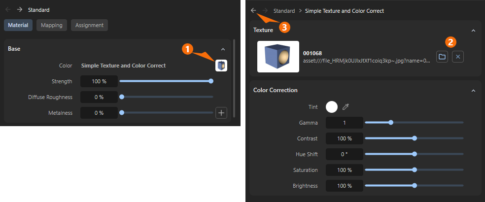
1After loading, a thumbnail of the texture appears in place of the + button. This texture then replaces, for example, the color value or percentage value that was previously displayed there. The texture is therefore evaluated in the unit of the property it controls. When loading into areas that use a *Color*, the texture’s color values are also used. Where a percentage value defines, for example, the *Metalness* or *Roughness* of a surface, only the brightness values of the texture are used.\
Clicking on the thumbnail of the loaded texture opens an additional dialog box where you can find the image-editing functions described earlier for adjusting the texture.
2On the corresponding *Color Correction* page of the texture, to the right of the enlarged preview, there are also two buttons: one for loading a different texture (**folder** icon) and one for removing the texture (**x**).
3To return from the *Color Correction* settings to the material settings, click the left-pointing arrow at the top of the *Attribute Manager*.
### Base
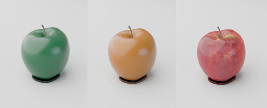
*Color*
Defines the primary color of the surface for diffuse and metallic reflections (also see examples in the above figure). The intensity of the color is the product of multiplying by the *Strength*.
> **Note:** When *Metalness* is greater than 0 the *Base Color* determines the color of metallic reflections at facing angles. The effect of the color therefore diminishes as the metallicity increases in the areas of the surface that are shaded by light, and is concentrated in the coloring of reflective areas viewed from a perpendicular angle.
*Strength*
Controls the intensity of diffuse or metallic reflections when multiplied by the *Base Color*. A value of 100% represents full intensity, while 0% reflects no light.
*Diffuse Roughness*
Controls the micro-surface roughness of diffuse reflections using an energy preserving Oren-Nayar (EON) reflection model. This is useful for simulating matte or dirty surfaces. Higher values represent rough surfaces like rock and sand, scattering light in more random directions. Lower values represent smooth surfaces that reflect light more evenly resulting in greater surface definition. A *Diffuse Roughness* of 0% scatters light equally in all directions using Lambertian reflection.
*Metalness*
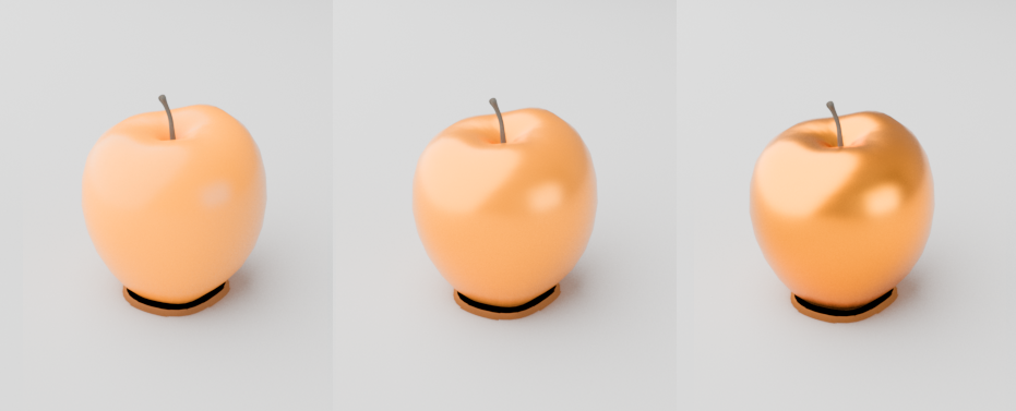
Controls if the material behaves as a non-metal (dielectric) or metallic material. A value of 0% represents a non-metal material that can exhibit diffuse reflections, subsurface scattering, or transmission. A value of 100% represents a fully opaque metallic material — blocking any subsurface scattering or transmission and replacing diffuse reflections with metallic reflections. Values between 0% and 100% blend between the two behaviors (The illustration above shows *Metalness* values increasing from left to right).
When *Metalness* is used:
- The *Base Color* controls the color of reflections at facing angles.
- The *Specular Color* controls the edge tint color of reflections, at grazing angles along the edges of a surface.
- The *Specular Strength* controls the reflection intensity of the metal.
### Specular
Most real-world materials exhibit some amount of reflection. The two most visible aspects of reflection are its blurriness (driven by *Roughness*) and its strength (driven by the *Strength* and *IOR* settings).
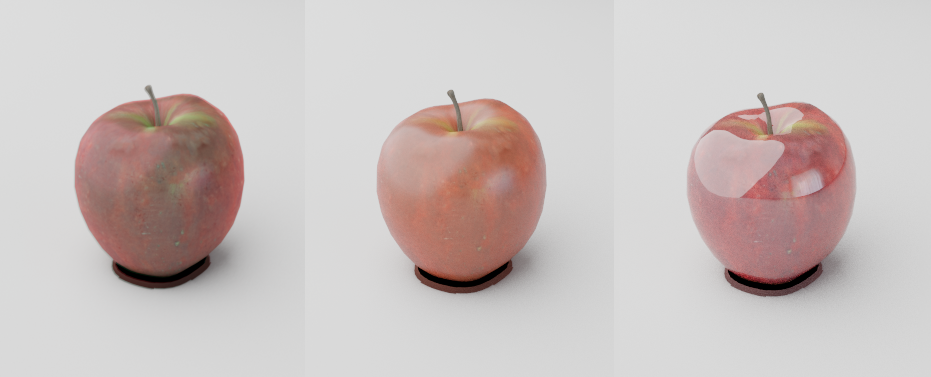
*Color*
Controls the overall specular reflection color for non-metals and the reflection color at grazing angles for metallic materials. For physically accurate non-metals this should be left at the default white.
*Strength*
Controls the intensity of specular reflections by multiplying with the *Specular Color*. Higher values exhibit strong reflections while lower values exhibit weaker reflections.
*IOR*
*IOR*, short for *Index Of Refraction*, controls how light is reflected off of non-metals as well as how light is bent in transmissive materials. *IOR* is a physical based value so you can look up the matching value for a specific material online for accurate results, but most dielectric materials have an *IOR* between 1.4-1.6. Higher values result in more intense reflections while lower values result in weaker reflections.
*IOR* defines how fast light rays move through a medium, when a light ray passes between mediums with a different *IOR* the ray bends because of the difference in the speed of light for each medium.\
A light ray moves through air at the speed of light but slows down when it passes into glass or water causing it to bend and distort.
A value of 1 represents how light behaves in a vacuum, light rays are not bent since a vacuum does not interact with the rays at all. Most materials never have an *IOR* below 1 since it would mean light travels faster in this medium than it does in a vacuum.\
Some typical *IOR* values are:
- *Water*: 1.333
- *Glas*: 1.49-1.6
- *Plastic*: 1.46
- *Marble*: 1.49-1.66
- *Asphalt*: 1.58
- *Aluminuim*: 1.39-1.44
- *Iron*: 2.95
- *Copper*: 2.4-2.7
- *Chromium*: 2.97
*Roughness*
Controls how smooth or rough the specular reflection should be. Higher values scatter light in more random directions resulting in blurry reflections, a value of 100% results in an almost diffuse appearance. Lower values concentrate the light into sharper and more distinct reflections, a value of 0% results in a perfectly polished surface.
*Roughness* simulates microfacet surface imperfections by controlling how light bounces off the surface. As *Roughness* increases reflected light scatters all over the scene, simulating a bumpy uneven surface, so less of it bounces back into the camera which results in a visually dimmer overall reflection. As *Roughness* decreases the reflected light is scattered less, simulating a very smooth surface, with more of it bouncing back directly into the render camera resulting in brighter and sharper reflections. This is why wet materials tend to look shiny, liquids — which tend not to exhibit any surface roughness — fill in the gaps of an otherwise porous surface creating the appearance of a smooth surface and brighter reflections. However it's important to note, the amount of light reflected back is always the same thanks to conservation of energy, regardless of the *Roughness* value.
*Anisotropy*
[Video: rsSurface_Tangent_Aniso_0-1_Rough_04_anim.mp4](https://help.maxon.net/rva/en-us/Content/Resources/Images/rsSurface_Tangent_Aniso_0-1_Rough_04_anim.mp4)
> **Note:** Requires a *Specular Roughness* greater than 0%.
Controls how far coat reflections stretch in a particular direction. Anisotropy is used to represent materials like brushed metal that have elongated specular reflections due to their fine grooves rather than round reflections that would occur with a smooth surface. Low values represent isotropic reflections with less stretching while higher values result in more stretching with high directionality.
*Angle*
This allows you to rotate the direction of travel of the anisotropically distorted highlights and reflections.
### Transparency
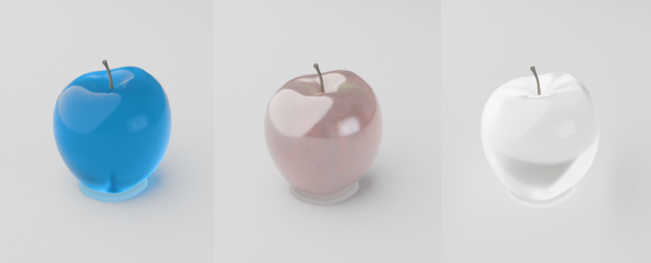
These settings set the refractive transparency of the material. A full refraction calculation needs a double sided geometry. To see refractive tint one a single sided geometry, you have to activate the *Thin Walled* option in the *Geometry* section of the material.
> **Note:** Note that *Specular Roughness* is also used to scatter transparency. For example, increasing the *Specular Roughness* allows you to simulate frosted glass or cloudy liquids.
*Color*
Controls the transmission color. So this is the correct setting for tinted glass or colored liquids.
*Strength*
Controls the amount of light that can pass through the surface. Useful for transparent materials like glass and liquids.
> **Note:** A *Transparency Strength* of 100% overrides all *Base* layer shading attributes except *Metalness*. So if you want to mix colored surface shading with transmissive properties make sure to use a *Transparency Strength* lower than 100%.
### Fuzz
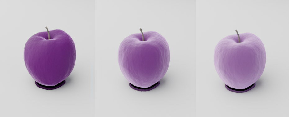
*Color*
Controls the color tint of the Fuzz reflection.
> **Note:** Cloth model by Fuchs & Vogel
| | | | |
| --- | --- | --- | --- |
| 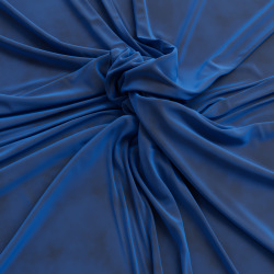 | 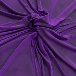 | 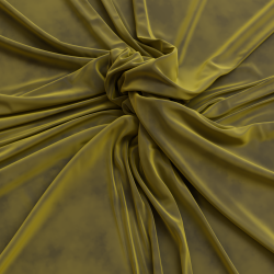 | 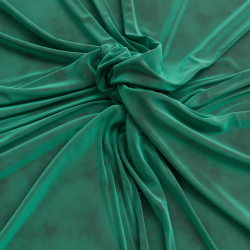 |
| Fuzz Color: Blue | Purple | Yellow | Teal |
*Strength*
Controls the intensity of the *Fuzz* reflection. With *0%* the *Fuzz* effect is disabled.
| | | |
| --- | --- | --- |
| 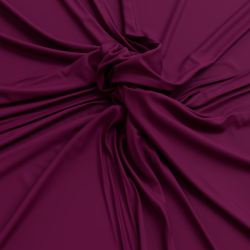 | 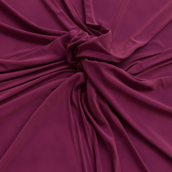 | 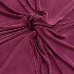 |
| Fuzz Strength: 0%
Fuzz Color: Light Pink | 50% | 100% |
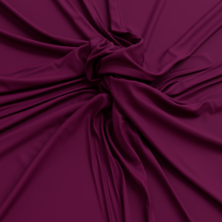
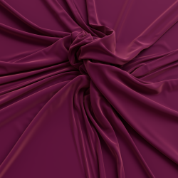
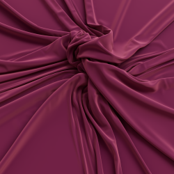
*Roughness*
This controls the roughness of the *Fuzz* reflection, higher values result in a softer look.
| | | |
| --- | --- | --- |
|  |  |  |
| Fuzz Roughness: 0% | 20% | 50% |
### Coat
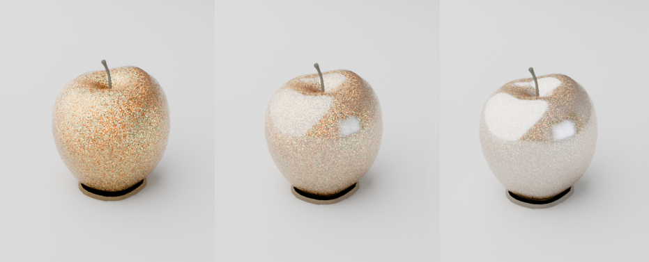
These options define an additional reflection layer over the material. This is helpful to emulate properties such as varnish, the clear coat of car paint, or slimy and wet surfaces. The coating layer also has its own Bump Map input which allows you to define details such as scratches separate from the base of the material, or leave as perfectly smooth.
> **Note:** Since the coating layer covers the entire material it will indirectly affect the strength of other material properties due to energy conservation, such as *Base* shading, *Specular* and *Transparency*.
*Color*
Controls the coat reflection color, using a different coat color compared to the primary reflection a two-tone effect can be achieved.
In the examples below a rough metallic shader with a triangular bump map pattern can be seen with a very shiny coating on top.
| | | | |
| --- | --- | --- | --- |
| 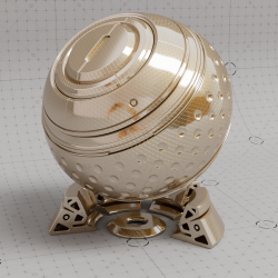 | 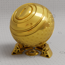 | 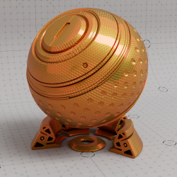 | 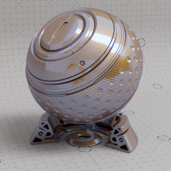 |
| Coat Color: White (default) | Yellow | Red | Blue |
*Strength*
Controls the intensity of the coating reflection. Coat is disabled at 0%.
| | | |
| --- | --- | --- |
| 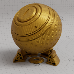 | 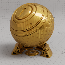 | 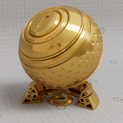 |
| Coat Strength: 0% | 50% | 100% |
*Darkening*
It's common for a *Coat* layer to saturate colors and darken the surface beneath due to numerous internal reflections that take place in the *Coat*. Darkening controls how intensely the *Coat* layer is able to darken the layers beneath. High values represent heavy saturation and darkening while low values reduce the effect. By default darkening is used at the heaviest level (100%) but a value of 0% disables it completely.
High *IOR* values also increase the number of bounces which leads to even heavier darkening.
| | |
| --- | --- |
| [Video: rsSurface_Tangent_Coat_Darkening_0-1_anim.mp4](https://help.maxon.net/rva/en-us/Content/Resources/Images/rsSurface_Tangent_Coat_Darkening_0-1_anim.mp4) | [Video: rsOpenPBR_Coat_Darkening_0-1_anim.mp4](https://help.maxon.net/rva/en-us/Content/Resources/Images/rsOpenPBR_Coat_Darkening_0-1_anim.mp4) |
| Coat Darkening: 0% - 100% | 0% - 100% |
*IOR*
The index of refraction used to calculate the strength of the coatings fresnel effect. An IOR of 1.0 disables the coat.
Note that the clearly defined coating specular highlight compared to the rough base metal reflection.
| | | | |
| --- | --- | --- | --- |
| 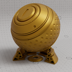 | 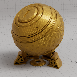 | 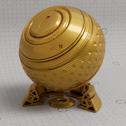 | 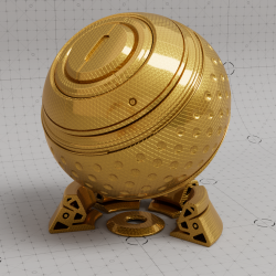 |
| Coat IOR : 1 | 1.5 | 2 | 3 |
*Roughness*
This is the roughness of the surface reflection. A *Roughness* value of 0% means perfectly 'polished', or full glossiness. A *Roughness* value of 100% means almost diffuse appearance.
| |
| --- |
| [Video: rsStandard_Mat_Coat_Roughness_0-1_anim.mp4](https://help.maxon.net/rva/en-us/Content/Resources/Images/rsStandard_Mat_Coat_Roughness_0-1_anim.mp4) |
| Coat Roughness: 0% to 100% |
*Anisotropy*
This allows to you stretch coat reflections in a direction based on the anisotropy rotation. *Anisotropy* is used to emulate materials such as brushed metals where surface roughness is focused in a particular direction. *Specular Roughness* must be set above 0% to see the effect.
| | | |
| --- | --- | --- |
| 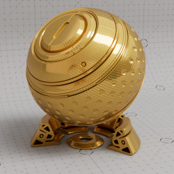 | 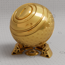 | 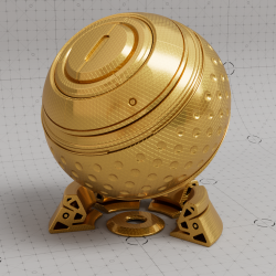 |
| Coat Anisotropy: 0% | 50% | 100% |
*Angle*
This controls the anisotropic Coat reflection direction. Similar to the *Specular Anisotropy Angle* parameter.
*Bump Map Type*
A Bump Map or a Normal Map (both can be used here) can be used to vary the shading of a surface, as if there were, for example, grooves or scratches, causing reflections and brightness gradients to behave differently. The advantage of this is that it allows you to simulate fine irregularities and details without having to change the object’s geometry. Various types of textures are generally compatible with this approach:
- *Height Field*:This mode expects greyscale height based texture maps for bump mapping. Dark areas of the loaded texture then appear as if they are recessed, and light areas appear as if they protrude from the surface.
- *Tangent-Space Normal*: This mode expects tangent-space normal maps for normal mapping. Here, textures with RGB values are required to describe the X, Y, and Z components of surface vectors. By design, this can be much more accurate than using simple grayscale textures (*Height Field*). However, this requires that normal maps be calculated specifically for this purpose. Using standard RGB images will not yield usable results in this context.
- *Object-Space Normal*: This works similarly to *Tangent-Space Normal*, so it also expects an RGB texture. This time, however, the normal directions are expected relative to the object's axis system rather than relative to the surface. The normal map must have been created specifically for this purpose. This applies to both normal modes of the bump map.
*Object-Space Normal* maps contain normal information specific to the object it should be applied to. In Object-Space the up axis is directly tied to the up axis of the object itself and therefore using an *Object-Space Normal* map on any object other than the one it is intended for will not look right.
*Tangent-Space Normal* maps contain normal information that can be applied to any object and behave properly. In Tangent-Space the up axis is relative to an objects surface normal and therefore using a *Tangent-Space Normal* map on any object will behave correctly.
*Bump Map*
Use the **+** button to load a bitmap file that matches the selected *Bump Map Type*.
*Bump Scale*
This scales the height value that is read from the *Bump Map* texture. A value of 0.0 effectively disables the technique, yielding just the surface normal. Greater values increase the bump effect.
> **Note:** Because this is a visual trick, very large values will not yield good results, so in those cases you should use *Displacement* mapping instead (see *Geometry* settings of the material).
### Emission
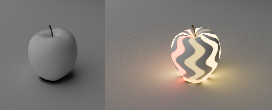
*Emission* can be used for surface illumination effects, and will emit light into the scene when the effect is strong enough based on the *Emission Strength*.
*Color*
Controls the color of the emission. *Emission* casts light in the scene by using indirect global illumination rays to cast diffuse lighting on other objects in the scene. At the same time, it brightens the material regardless of the surface lighting.
*Luminance (cd/m^2)*
Controls the intensity of the emitted light in nits when the emission color is white. Higher values result in brighter colors and stronger global illumination. You can also load a texture here. The brightness values of this texture can be used to vary the emission strength.
Note, *Emission* intensity is affected by the layers that sit above it — *Coat* and *Fuzz*. For example, *Coat* can dim emission intensity but if emission is bright enough this may not be apparent.
### Geometry
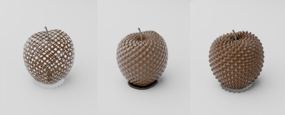
*Thin Walled*
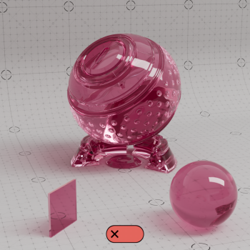
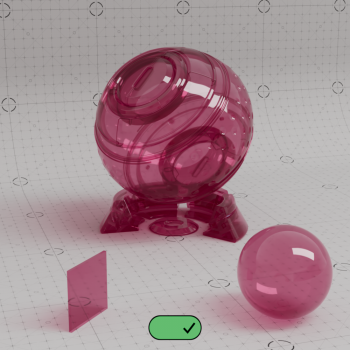
This option is useful for thin refractive materials such as a pane of glass, where the ray-bending effect is not noticeable and modeling actual object thickness is not worth it. When this option is enabled, refraction rays will enter and immediately exit the medium without bending the rays.
#### Thin Transparent Materials in Detail
The *Thin Walled* option is available for rendering thin transparent objects that don't actually have modeled thickness, such as a pane of glass. For very thin objects, refractive rays will not travel enough of a distance inside the object before exiting to show any noticeable bending effect. Enabling this option preserves the reflection Fresnel effect while internally disabling any medium interface transition math that would allow rays to bend.
In the examples below you can see a noticeable difference when this option is enabled. When enabled by default, the refractions bend and distort realistically - however, when disabled no bending occurs and instead the background can be seen straight through to the other side.
| | |
| --- | --- |
|  |  |
| Thin Walled: disabled | Thin Walled: enabled |
*Opacity*
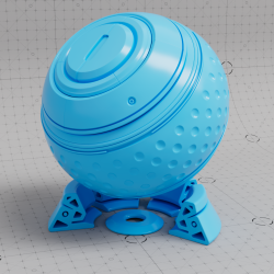
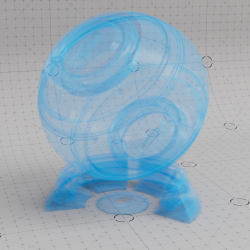
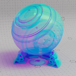
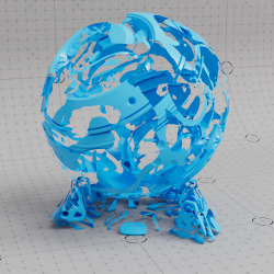
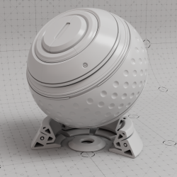
This color controls the overall opacity of the material, with colors closer to white being more opaque. An opacity of black means the material will be fully transparent.
Grey-scale values are typically used to describe opacity but other colors can be used with varying effects, the resulting refraction color is the inverse of opacity color.
| | | | | |
| --- | --- | --- | --- | --- |
|  |  |  |  |  |
| Opacity Color: White
Base Material: Blue | Grey | Black | Green | Textured |
|  | 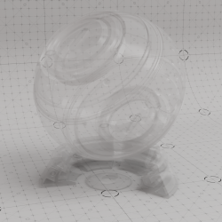 | 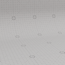 | 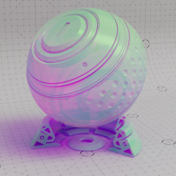 | 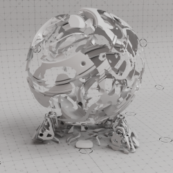 |
| Opacity Color: White
Base Material: Grey | Grey | Black | Green | Textured |
*Bump Map Type*
A Bump Map or a Normal Map (both can be used here) can be used to vary the shading of a surface, as if there were, for example, grooves or scratches, causing reflections and brightness gradients to behave differently. The advantage of this is that it allows you to simulate fine irregularities and details without having to change the object’s geometry. Various types of textures are generally compatible with this approach:
- *Height Field*:This mode expects greyscale height based texture maps for bump mapping. Dark areas of the loaded texture then appear as if they are recessed, and light areas appear as if they protrude from the surface.
- *Tangent-Space Normal*: This mode expects tangent-space normal maps for normal mapping. Here, textures with RGB values are required to describe the X, Y, and Z components of surface vectors. By design, this can be much more accurate than using simple grayscale textures (*Height Field*). However, this requires that normal maps be calculated specifically for this purpose. Using standard RGB images will not yield usable results in this context.
- *Object-Space Normal*: This works similarly to *Tangent-Space Normal*, so it also expects an RGB texture. This time, however, the normal directions are expected relative to the object's axis system rather than relative to the surface. The normal map must have been created specifically for this purpose. This applies to both normal modes of the bump map.
*Object-Space Normal* maps contain normal information specific to the object it should be applied to. In Object-Space the up axis is directly tied to the up axis of the object itself and therefore using an *Object-Space Normal* map on any object other than the one it is intended for will not look right.
*Tangent-Space Normal* maps contain normal information that can be applied to any object and behave properly. In Tangent-Space the up axis is relative to an objects surface normal and therefore using a *Tangent-Space Normal* map on any object will behave correctly.
*Bump Map*
Use the **+** button to load a bitmap file that matches the selected *Bump Map Type*.
*Bump Scale*
This scales the height value that is read from the *Bump Map* texture. A value of 0.0 effectively disables the technique, yielding just the surface normal. Greater values increase the bump effect.
> **Note:** Because this is a visual trick, very large values will not yield good results, so in those cases you should use *Displacement* mapping instead.
*Displacement*
Use the **+** button to load a bitmap file that matches the selected *Bump Map Type*.\
The rendering of a loaded texture is similar to *Bump Mapping*, except that with *Displacement*, it is not only the orientation of the surface normals that is altered, but the shape of the surface itself. The selection of the *Bump Map Type* is also used to determine the expected type of displacement texture, since typically only one of these options is used at a time. For example, for extreme close-ups, you may actually need to deform the geometry using *Displacement*, or you may find that the simulated surface detail provided by *Bump Mapping* is sufficient.
*Displacement Scale*
This scales the displacement value in scene units that is read from the texture. A value of 0.0 effectively disables the technique, yielding the original surface. Greater values increase the displacement effect. Negative values invert the direction of the displacement. The default is 1.0.
*Displacement Min*
*Displacement Max*
These values define the limits for the smallest and largest offset of the surface caused by the loaded *Displacement* texture.
## The Material Projection
In this section, you can specify how the material is applied to objects.
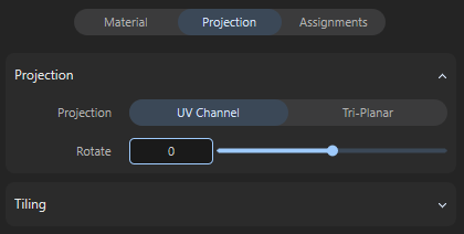
The Projection settings for materials.
### The Projection Group
Here you can set the rotation, size, and repeat rate of the material. In addition, there are two different **Projection** methods available for applying the material to surfaces, depending on whether your object has suitable UV coordinates or not.
#### Projection Mode
There are two different options for projecting the material onto the surfaces:
- *UV Channel*: If available, the UV coordinates that the object already has. These UV coordinates can be used to individually define the direction, scaling, and position of a material on the surface. However, the UV coordinates must have been assigned and edited beforehand and can only be modified to a limited extent in this mode, e.g., to adjust the rotation or size of the material. If there are no UV coordinates on the object that are suitable for the desired material assignment, this can be compensated for by switching to *Tri-Planar*.
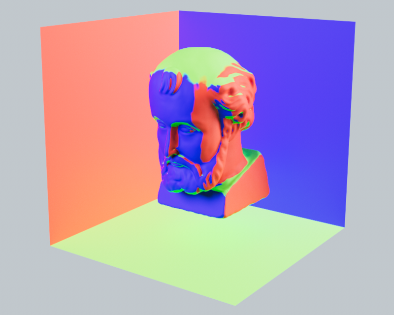
- *Tri-Planar*: In this mode, no UV coordinates are required for the objects, or they are ignored. Instead, the material is projected onto the surface of the objects simultaneously along the three typical object axes X, Y, and Z. This technique often allows for high-quality material assignment even when no UV coordinates are available.\
The following illustration clarifies the principle. The colored areas indicate the material that is projected onto the object along the X, Y, and Z directions. The different areas of the object are captured by this projection according to their inclination to these three main planes.
#### Rotate Value
Here, you can specify an angle by which the material should be rotated. For example, the grain direction of wooden planks can be rotated to match the object.
[Video: Mat_Rot_Ani.mp4](https://help.maxon.net/rva/en-us/Content/Resources/Images/Mat_Rot_Ani.mp4)
Example of Rotate adjustments for the sofa material.
#### Size Value
This setting is only available for the Tri-Planar setting and determines the size of the texture projections. Smaller values will then result in more repetitions of the material on the surface by default.
### The Tiling Group
#### Tiles U/V Values
If the material contains shaders or textures, these values can be used to indirectly adjust their size within a material tile. Values above 1 reduce the size of the textures, while values below 1 enlarge them. The letters **U** and **V** stand for the horizontal and vertical directions within the texture tile. With **Tiles U** = 2, the material is compressed sideways to half its size. This means that two copies of the material fit into one material tile.
[Video: Mat_Scale_Ani.mp4](https://help.maxon.net/rva/en-us/Content/Resources/Images/Mat_Scale_Ani.mp4)
Example of Tiling adjustments for the sofa material.
The example above in the video demonstrates the effect of different texture scales within the material tiles. In each case, **Wrap U** und **Wrap V** is configured to *Repeat* the material, which means that the material is automatically repeated endlessly to fill the surface.
#### Offset Values
Imagine the image elements within the material as if they were painted on a tile. Internally, such a texture tile always has an edge length of 1 in the horizontal and vertical directions (corresponding to the width and height of the textures in the material). Using these **Offset** values, this texture tile can now be moved horizontally (first value) and vertically (second value). With the value pair 0.5 and 0.0 for example, the image elements in the material would be moved horizontally by half their width.
[Video: Mat_Offset_Ani.mp4](https://help.maxon.net/rva/en-us/Content/Resources/Images/Mat_Offset_Ani.mp4)
Example of Offset adjustments for the sofa material.
#### Wrap U/V Values
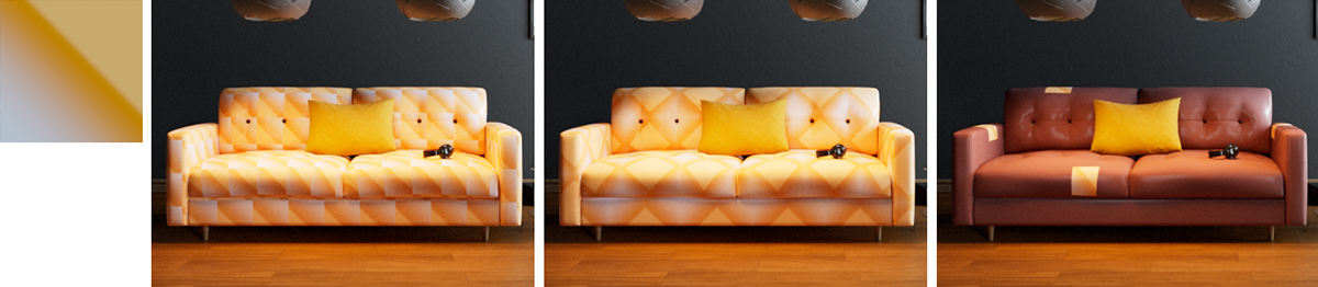
Examples of the available wrap modes. The texture used can be seen at the top left. The following renderings show the “Repeat,” “Mirror,” and “Clip” modes for the material (from left to right).
Whenever a material tile is smaller than the surface to be covered with the material, automatic repetition of the material tile can be activated. This effect is controlled by these settings:
- *Repeat*: This is the default setting and causes the material to be automatically repeated in the appropriate direction to cover the entire assigned object. The effect is comparable to laying floor tiles. Each added material tile is identical to the original tile and is only shifted in a U or V direction.
- *Mirror*: In this mode, copies of the original material tile are also automatically added in the U or V direction. However, every second tile is mirrored in the corresponding direction. This is helpful if, for example, the material has distinctive patterns but the edge structures are not identical, i.e., if the left edge of the material has different colors than the right edge. If the material tiles were simply placed next to or on top of each other, the transition from one tile to the next would be immediately noticeable. By mirroring the tiles alternately, this transition between adjacent tiles can at least be softened.
- *Clip*: It is not always helpful for a material to repeat endlessly and cover the entire surface. Think, for example, of applying a sticker or logo to an object. These elements should only be visible once on the surface and not multiple times next to or on top of each other. In these cases, select *Clip* so that the material is not repeated in the corresponding direction. The position of the non-tiled and therefore only once visible material can be influenced by the **Offset** values.
#### Flip U/V Options
These options allow you to mirror the UV coordinates of the surface used for material assignment separately for the U and V directions. This can be helpful, for example, if you are using materials with text elements or logos and these appear mirrored on the surface. Please note that mirroring the UV coordinates may also require the **Offset** values to be readjusted.
## The Material Assignments
This lists the names of all objects to which the material has been assigned. Right-clicking on individual entries opens a context menu that allows you to select the corresponding object, making it easier to find in the viewport or object list. As shown in the right-hand side of the figure below, selected objects automatically display the materials used with them in the lower *Attribute Manager*. Moving the mouse pointer over these entries displays icons that can be used to call up settings such as color correction or projection, or to remove the material from the surface.
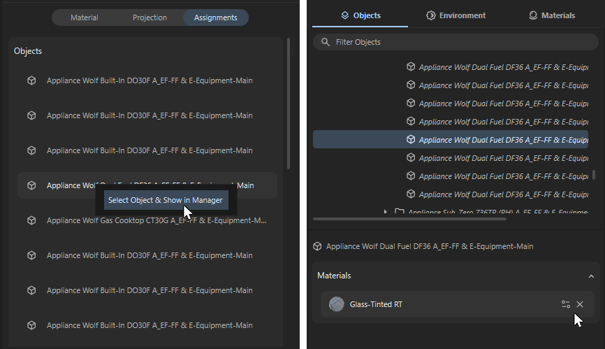
By right-clicking on entries in the "Assignments" list (on the left in the figure), you can select the objects to which the material has already been assigned (shown on the right).