- Manual Update
- Example of DynaMesh Process
- Working with Multiple Meshes
- DynaMesh with Polypaint and Textures
- DynaMesh Actions
Manual Update
Keep in mind that the DynaMesh creation is not an automatic process. You will need to update your geometry when you feel that you need it. To perform this step, you must be in Edit >> Draw Mode and simply hold the CTRL key while click/dragging on an empty space of the document in the same way that you would to a clear a mask on your model. Upon receiving this command, DynaMesh will update your geometry in a fraction of second.
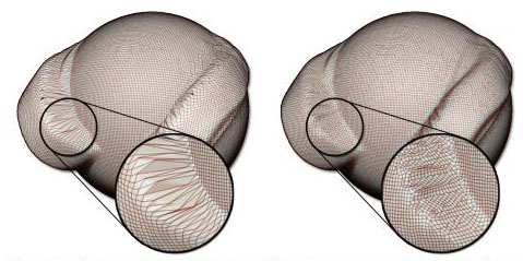
On the left, the mesh topology has been stretched after several brush strokes. On the right, a new topology with a constant tyopology has been recreated, ready to be sculpted.
With a high resolution and/or a large bounding box, DynaMesh will need more time to update your mesh. However, productivity is not lost because most of the time, this update process will still be done in less than a second (depending on your computer CPU performance).
- If you wish to add your own shortcut to DynaMesh this can be accomplished by applying a hotkey to the “Add” button in the DynaMesh options.
- The DynaMesh update can only be performed when ZBrush is in Draw mode and not when in TransPose (Move, Scale or Rotate) mode.
- If your model already has a mask applied, you must clear the mask before being able to update the DynaMesh.
DynaMesh and Surfaces/Restrictions
The DynaMesh remeshing process can only work on volumes and not on surfaces. Surface detail can be lost based on your Resolution setting (found directly under the DynaMesh button).
Example of DynaMesh Process:
- Load a Polymesh3D. A good example can be the DefaultSphere project, available in the LightBox Project tab.
- Go to the Tool >> Geometry menu and click the DynaMesh button. You will now be in DynaMesh mode.
- Pick one of your favorite brushes like the Clay or Clay Buildup and start sculpting as usual. Your model will react exactly like traditional sculpting clay would.
- When you encounter distortion, stretched polygons or have the sense of missing some polygon density in any area, you can ask ZBrush to update your mesh. To do this, simply hold the CTRL key and drag a small rectangle outside of the mesh in any open space of the canvas in the same way you would to clear a mask. The mesh will automatically update with new geometry, ready for additional deformations or brush strokes.
- In addition to the brushes, you can use TransPose with masks to make local or global deformations. Just remember that you must clear your mask and be in Draw Mode before you can update your DynaMesh.
- You can also use Mesh Insert brushes to incorporate other models into your DynaMesh object. For example, you can have premade noses, ears, eyes and mouths, ready to add to a DynaMesh whenever you need one. This is a great solution to quickly build figures without having to always redo your work.
- When you have finished building your low or medium resolution base mesh and want to start refining your figure with detail sculpting, quit the DynaMesh mode. Your model will become a traditional Polymesh3D. It will now be ready to add subdivisions for fine details.
Working with Multiple Meshes with a DynaMesh
It’s possible to work with multiple meshes while in DynaMesh mode. Any inserted object which is remeshed with the original one can remain separate by turning on the Group option located next to the DynaMesh button.
When the Group option is enabled, ZBrush will use polygroups to maintain separate geometry shells on a mesh that will still appear to be one piece of geometry and can be sculpted as such. You can have a lot of fun with the Group option in DynaMesh while using the new Slice Curve brush. (Learn more about the SliceCurve brush in the New Brushes section of this document.)
As already stated, this grouped mesh behaves as a single piece of clay. The only way to see the different polygroups is by enabling the PolyFrame button on the right side of the interface or by clicking the Transform >> PolyFrame (PolyF) button (Shift+F to toggle PolyFrame). Each Polygroup will be displayed with a different color.
If the Group option is enabled and a mesh has different polygroups, the DynaMesh remesh action will maintain these PolyGroups. At the same time it will fill any holes or gaps between dissociated objects. The Slice Brush creates new PolyGroups on the fly based on a curve or line that you draw. Combined with the DynaMesh and the Group option, this lets you easily cut objects into separate watertight volumes.
Note: The DynaMesh resolution limit is per-SubTool. Adding more groups to your model will not increase the resolution limit of the DynaMesh. All groups will share the same maximum resolution. If you wish to have different meshes with different DynaMesh resolutions, you must use different SubTools which can then each have a different DynaMesh resolution.
DynaMesh with PolyPainting and Textures/UVs
The DynaMesh is a raw set of polygons that doesn’t include UVs. It is in fact impossible to have UVs on a DynaMesh due to the fact that UVs are dependent upon topology – something that changes every time you remesh. If your original model has UVs, switching to DynaMesh mode will delete all UV information. A texture will not be able to be applied to a DynaMesh until turn off DynaMesh mode and create new UVs. This also naturally means that textures previously created for the model will no longer wrap correctly after using DynaMesh.
This restriction only applies to textures and UVs, however. A DynaMesh is still made up of polygons and so it supports PolyPainting. You can apply PolyPaint at any point during the process of creating with the DynaMesh feature. PolyPaint information will not be lost even when you remesh a DynaMesh to redistribute the geometry. Please do bear in mind that if your DynaMesh resolution is lower than the original polymesh model, you will experience a loss of PolyPaint quality when activating the DynaMesh feature. Also keep in mind that because DynaMesh regularly updates the mesh and changes the geometry count as you work, this can affect any PolyPaint.
In short, painting while DynaMesh is in use should be treated the same way as mesh generation – as a way of blocking out your design before you move on to refining and detailing.
Note: If you have a pre-existing model with texture you can keep that texture when activating DynaMesh. To do this, subdivide the model to have a number of polygons approximately equal to the texture resolution. Apply the texture and use Tool >> Texture Map >> New From Polypaint to convert the texture to paint. You can now activate DynaMesh, which will delete the UVs but keep the PolyPaint. The resolution of the paint will of course depend on the DynaMesh resolution, which does mean that you are likely to lose some of the texture’s details.
DynaMesh Actions:
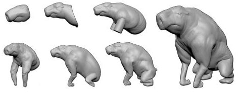
A creature based on a simple sphere and cylinder inserted meshes. Model by Matthew Kean.
- Inserting additive meshes (Add): By default, all new inserted elements will be additive meshes. This means that when doing the remesh operation, the inserted items will be merged as one element with the original DynaMesh.
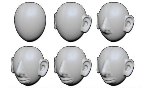
This is an example of the combinaison of the insert brushes with custom meshes like ears, lips, nose, etc. combined with the DynaMesh. The ears are inserted first, then the nose and lips. The new topology is generated by the DynaMesh and some transition has been done with the help of the Smooth brush. In few clicks, create a base mesh with just presets brushes!
- Inserting negative meshes (Sub): When holding the Alt key while inserting a mesh, ZBrush will consider it to be a negative mesh. This means that when the remesh is completed, the inserted mesh will be removed from the previous mesh and create holes. The result is similar to a subtraction Boolean operation, but without the messy polygons usually associated with Booleans.
You can insert multiple meshes and add or subtract them all at once via a single remesh operation. You can even mix additive and negative meshes, creating different combinations at once.
On the left, the original mesh with the negative mesh inserted in white color. On the center and right, the final result.
To visualize the negative meshes before the remesh operation of the Dynamesh, switch the PolyFrame display (located in the Transform palette): the negative meshes have a white PolyFrame color.
- Intersecting meshes (And): When inserting a negative mesh (see Sub action) on top of a positive mesh (see Add action), the remesh action will create geometry only where the two meshes intersect each other. All other geometry will be removed. This operation is very similar to the SubTool Remesh intersection option.
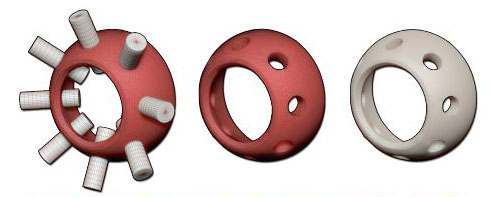
- Creating a Shell: You can create an internal thickness within any DynaMesh by first inserting a negative mesh (Sub). Clicking the Create Shell button will then place a hole where the Insert brush was used and an internal thickness will be added to the DynaMesh. The Thickness slider will let you change the size of the thickness, which is inward from the mesh surface. (In other words, it will be inside the model rather than inflating the surface.) This tool is perfect for people who wish print their models in 3D as it will reduce the amount of material for printing and so reduce costs.
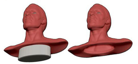
The Shell creation: on the left, the original mesh and a negative mesh in white inserted on the location to create the opening. On the right, the final result with the shell thickness visible at the opening location.
If you do not wish to have a hole when Create Shell button is pressed make sure to move the negative inserted mesh away from the mesh before remeshing.
Note:The shell thickness calculation will consider local thickness across every point of the model’s surface. Any place where multiple shells intersect will not create any shell. Put another way, if the Thickness value is too large for the local mesh size, a shell won’t be able to be created at that location. An example would be if the slider is high the a character with small fingers. In that case the body would receive a shell but the fingers would not.