Making single-sided meshes a snap
Two major additions have been made to ZModeler in ZBrush 2021: Edge Extrude for creating single-sided meshes and re-topology. And Inset Equidistant for creating insets that don’t change your existing topology profile.
Edge >>Extrude
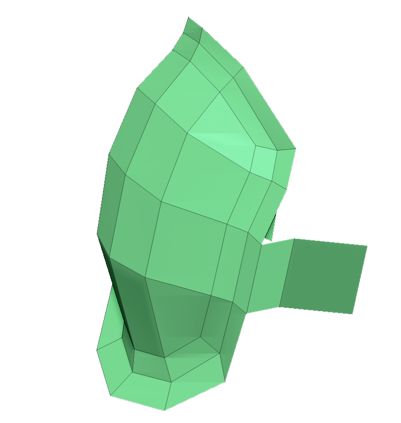
Building a single-sided mesh with Edge Extrude
- Select or append the PolyMesh3D star.
- Set the Tool >> Initialize X, Y and Z sliders to 1 and press the QGrid button. This creates a single polygon from which you can start building whatever you want.
- Turn on Tool >> Display Properties >> Double to see both sides of your model.
- Select the ZModeler brush, position the cursor over an edge and press the spacebar. Select “Extrude” from the Edge Actions. For an explanation of the options, see the Edge Extrude Modifiers section.
- Click and drag the edge to extrude.
Use Dynamic Subdivision to see your model in a subdivided preview. Add thickness if you want by activating the Thickness slider.
When extruding the edge of a single polygon, tap Alt to change to extruding the Edgeloop and hold Alt to extrude the Polyloop.
Re-Topology
The new ZModeler Edge Extrude option can be used for re-topology.
Getting started.
- Select or append the PolyMesh3D star.
- Set the Tool >> Initialize X, Y and Z sliders to 1 and press the QGrid button. This creates a single polygon.
- Use the Gizmo3D to position the polygon on the surface of the SubTool where you want to start. Turn on transparency to better see what you are doing.
- Press the Gizmo3D: Mesh To Axis to center the polygon.
- If you want to use Symmetry, use Tool >> Geometry >> Modify Topology >> Mirror And Weld to divide the polygon in two.
- Select the ZModeler brush. Position the cursor over an edge and press the spacebar. Select Extrude and make sure the Snap To Surface option is selected. Taper Sides can also be useful.
- Create your topology.
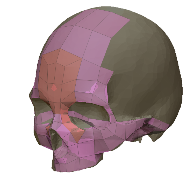
An example of creating new topology using Edge Extrude
ZBrush artist: Daisuke Narukawa
Extrude >> Modifiers
Extend Surrounding Faces
When an unselected face edge is extruded the surrounding face edges will be extruded as well.
Regular Extrude
The selected edge is extruded.
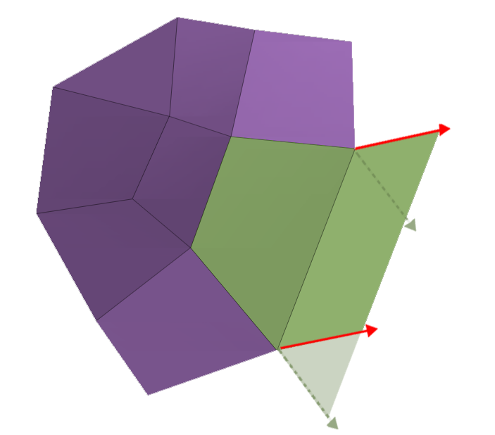
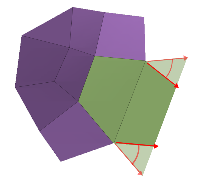
Free Angle
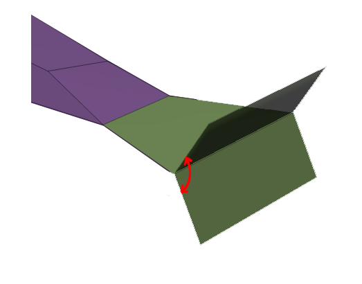
Free angle
The extrusion can be any angle to the polygon of the starting edge. Holding the Shift key can be used to snap in 5 degree increments. While drawing out the new extruded edge, tapping the Shift key will swap between all three angle options. (Free Angle, Planar Angle and Perpendicular)
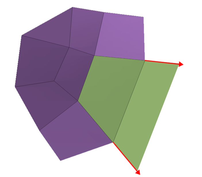
Planar Angle
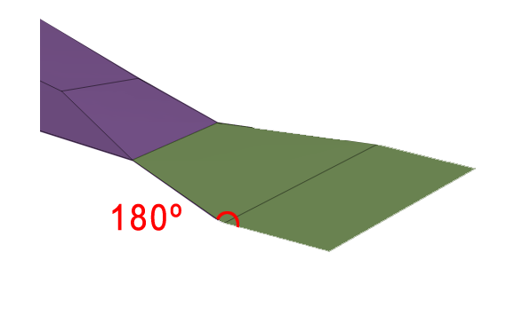
Planar Angle
Continues the extrusion on the same plane of the polygon of the starting edge. While drawing out the new extruded edge, tapping the Shift key will swap between all three angle options. (Free Angle, Planar Angle and Perpendicular)
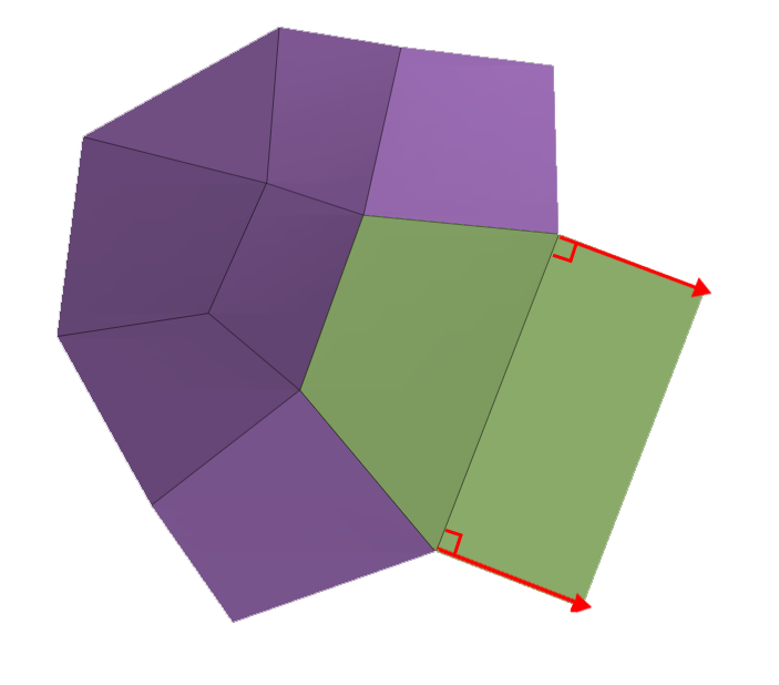
Perpendicular Angle
Perpendicular Angle
The extrusion is perpendicular to the polygon of the starting edge. While drawing out the new extruded edge, tapping the Shift key will swap between all three angle options. (Free Angle, Planar Angle and Perpendicular)
Free Sides
Free Sides
The sides of the newly extruded polygon can be an angle determined by cursor movement.
Extend Sides
Extend Sides
Extends the perpendicular edges of the extruded edge along the same angle of the edges from the original polygon.
Parallel Sides
Parallel Sides
The sides of the newly extruded polygon are parallel
Taper Sides
Taper Sides
The sides of the newly extruded polygon can be tapered by cursor movement up/down
Single Row
The extrusion is a single polygon of any length
Num Rows
The extrusion is divided by the number set in the slider. The polygons lengths will be determined by the extrusion. When this is enabled the CTRL key + moving your cursor back/forth can be used to interactively adjust the rows.
Row Size
The polygons are the length set in the slider and will be repeated as necessary along the extrusion
Free Move
The extrusion is free in space.
Snap To Surface
The extrusion will snap to the surface of underlying subtools.
Smart Attraction
Will actively try to merge with existing points.
Normal Attraction
Will try to merge points with existing points but only within a threshold that is determined by the average edge length.
No Attraction
Will not try to merge points with existing points, unless they are extremely close.
Force Symmetrical
This postprocess will ensure that edge points extruded from symmetrical edges will themselves be symmetrical. It will also do its best to connect points on the symmetrical plane when needed.
Don’t Force Symmetrical
Symmetry is only considered for finding input edges. The actual extrusion algorithm will not apply any specific process to make the resulting points symmetrical.
Edge >> Extrude Move
Edge Actions >> Extrude Move extrudes the edge by duplicating it. It is basically a simpler version of Edge Extrude. It has the following modifiers, which are identical to Extrude Edge: Single Row/Num Rows/Row Size; Free Move/Snap To Surface; Smart Attraction/Normal Attraction/No Attraction; Force Symmetrical/Don’t Force Symmetrical.
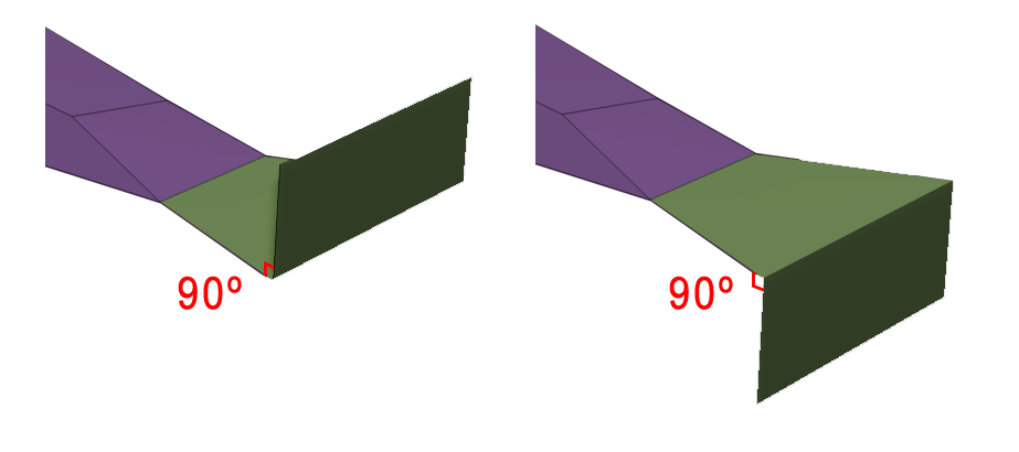
Edge >> Inset >> Equidistant
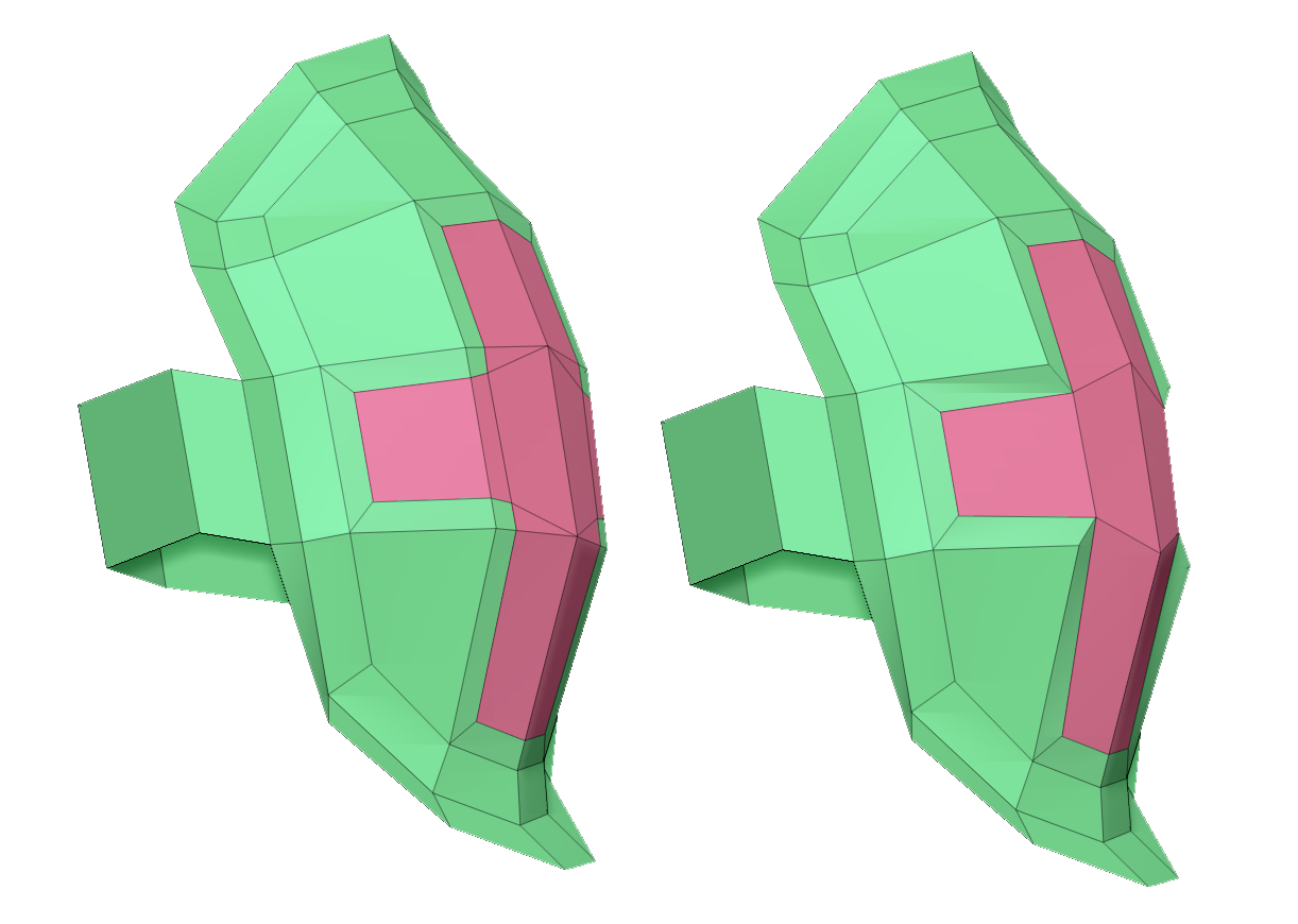
On the left, the result of Inset >> Equidistant.
On the right is Inset:Standard, showing the change in profile.
While standard Inset works as in previous versions and tends to distort the mesh, Inset Equidistant will maintain the shape profile and smoothness of the mesh.
Inset >> Modifiers
Center And Border
Will create a separate polygroup for the border and center.
Border Only
The inset will be the border and the center will be deleted.
Center Only
The inset will be the center and the border will be deleted.
Inset Region
The selected polygons will be inset as a whole. Giving equidistant insets along all of the faces.
Inset Each Poly
Each polygon in the selected area will be inset separately
Equidistant
The inset will be created equidistant all around the area, without changing the topology profile. Extra edges may be added to achieve this but the Custom Equidistant Snap (see below) can be used to limit the newly created edges where applicable.
Standard
The inset may change the profile but no extra quads/triangles are added.
Legacy
The inset doesn’t change the profile but will not necessarily be equidistant. Extra quads/triangles may be created.
No Size Limit
The inset can be any size
Default Size Limit
The inset will stop at the default size
Custom Size Limit
The inset will stop at the size set in the slider
Default Equidistant Snap
ZBrush will keep existing geometry and will intersect it around the edges to inset equidistantly at the standard distance. ZBrush will also precisely handle the intersection of inset segments. An additional point is added in the faces intersecting the median planes of vertices along the contour to be inset.
This is an equidistant snap threshold of any new intersecting points that can be snapped together and will work in most cases. This option will only work when Equidistant is enabled.
Custom Equidistant Snap
ZBrush will keep existing geometry and will intersect it around the edges to inset equidistantly at the desired distance. ZBrush will also precisely handle the intersection of inset segments. An additional point is added in the faces intersecting the median planes of vertices along the contour to be inset.
If the default threshold is creating more edges than desired, this slider gives a user-defined value for snapping. A higher value will limit the number additional edges that may need to be added to create an equidistant inset. This option will only work when Equidistant is enabled.
Point >> Move >> Snap to Surface
A new Point Action Move mode Modifier has been added – Snap to Surface. When moved close enough, the point will snap to the surface of underlying subtools.
In Move mode, points can be snapped together to form triangles.
Polygon >> Camera Perpendicular
A new Polygon Action has been added that will set the camera perpendicular to a given face.
Camera Perpendicular >> Modifiers
Recenter View
ZBrush will adjust the camera to face the clicked face and it will also recenter the camera to the center of clicked face.
Do Note Recenter View
ZBrush will rotate the camera so that it is facing the clicked face. The face’s center will be used as the rotation pivot, keeping the face center in place.
Alt selection in ZModeler
-
- Alt+click or Alt+drag on any “unselected” face allows selection of one face or several faces.
- Alt+click or Alt+drag on any “selected” face will deselect one face or several faces.
- Alt+double-click on a “selected” face will allow to deselect all faces.
Working with Subdivisions
Any ZModeler functions that do not change the mesh topology will now work on a model with subdivisons. So, for example, masking polyloops is now possible using a single click.