You will find below the different Actions that can be applied to the polygons of a model using the ZModeler brush. The ZModeler brush is context sensitive. To access its Poly menu you need to hover over a polygon before right-clicking or pressing the space bar.
Some Actions have behaviors that will be totally different depending on the selected Target. Also take note of the Edge Indicator widget when hovering over a polygon. This widget provides important directional information that may be used by the selected Action.
For descriptions of the Targets see the Polygon Targets page.
Add to Curve
The Add to Curve Action generates curves along the edges of the Targeted polygons. The created curves can be used in later stages with the Curve Actions or various Curve brushes.
Bevel
The Bevel Action slices off the edges of the corresponding Target, creating new edges with angled planes between them. The dimension of the generated bevel is determined interactively by dragging your stroke following the initial click.
Modifiers
- Single, Two, Four, Eight Row(s): Define the number of edges inserted in the bevel topology.
- Linear, Sharp, Soft Edge, Edge Sharpness: Define the shape of the bevel. Not only is the visible roundness of the bevel affected but also the distance between the edges, allowing for the bevel to look correct when using Dynamic Subdivision.
Bridge
The Bridge Action creates geometry between two polygons. The Bridge function can generated rounded surfaces when used with connected polys.
With the Two Polys Target, the Bridge Action connects the clicked polygons via a tube-like bridge. When using this Action a widget will prompt you to ‘Click 1st Poly’ then ‘Click 2nd Poly.’ With the 2nd click, the bridge will be created. When using this Action and Target; it can be easy to create a bridge that crosses existing polygons, resulting in irregular undesired topology.
With the Connected Polys Target, the Bridge Action connects two adjacent polygons and creates a new shape. The shape of the Bridge is drastically impacted by the different options and modifiers. To use the Target, hover over a poly and take note of the edge indicator. The edge indicator will point to the direction in which the Bridge will be created.
Modifiers (Connected Polys)
Dragging vertically and horizontally while clicking and dragging will allow you to dynamically reshape the bridge. Horizontal movement adjusts the curvature that is applied to the bridge. Vertical movement changes the amount of tessellation that is applied. Only the Interactive modifiers can by dynamically updated.
Pressing the Shift key while clicking and dragging will instruct ZBrush to automatically generate the optimal shape as specified by the modifier
- Interactive Curvature, Specified Curvature: Define the curvature of the bridge. This can be interactively controlled or set with a predefined value.
- Interactive Resolution, Specified Resolution: Define the resolution (number of tessellations) of the bridge. This can be interactively controlled or set with a predefined value.
- Align to Tangent, Normal: Define the direction in which the bridge is computed. Using Normal alignment is generally preferred when the adjacent polygons have a low angle between them.
- Variable, Constant Width: Allows the rows of the geometry being created to have a variation in width. This is most noticeable when one polygon’s edge width not shared by both polygon faces is wider compared to the adjacent polygon being bridged.
- Non Symmetrical, Symmetrical: Maintains an average width to the rows of geometry being created when bridging between two polygon faces with variable edge lengths on the none shared edge between the two polygons.
- Polygroup Rows, Flat: Determine what PolyGroups will be created for the new topology.
- Triangle & Quadrangles Sides Loop, Triangle Sides, Quad Sides: Define the topology of the side of the bridge. Extra edge loops can be created around the pivot edge and the topology can a mix of triangles and/or quadrangles.
Options (Connected Polys)
- The Bezier, Spline, Circle, Arcs, Arcs and Line, Round Corners, Small Rond Corners, Tight Round Corners, and Straight Lines: Define the shape of the geometry generated between the two polygons, based upon the selected modifiers.
- One Line: Produces a straight tube between the two clicked holes.
Alternative Operations (Connected Polys)
- Shift: Pressing this modifier while performing the click and drag allows ZBrush create the optimal shape based on the selected modifier.
Crease
The Crease Action applies edge creasing to the Targeted edges.
Modifiers
- All Sides, Long, Short Sides: Define which edges of the polygons will have edge creasing applied.
- All Faces, Polygroup Border, Polygroup Inner: Define the behavior of the creased edge, based on the existing PolyGroups for the selected Target.
- All transitions, Shallow, Sharp Transition: Define the behavior of the creased edge based on the topology of the model in the Targeted region. Shallow Transition will apply creasing where there are low angles between each polygon. Sharp Transition will apply creasing only on edges which form a sharp angle between polygons.
- All, Outer, Inner Targets: Specify whether to apply creases to all edges within the Target area, to boundaries only or to all edges except boundaries.
- All, Outer, Inner Edges: Specify whether to apply creases to all edges within the Target area or only to those at the boundaries of an opening.
Alternative Operations
- Alt: Uncrease already creased edges and vice-versa. Important: you must press the Alt key after clicking on the Target, without releasing the click. Pressing the Alt key before clicking will switch to the Temporary PolyGroup selection mode.
Delete
The Delete Action removes the Targeted polygons, creating a hole in the model.
Do Nothing
The Do Nothing Action is an empty action. When active, prevents performing any Poly Actions. This is useful when you know that you only want to use Point or Edge Actions, letting you work faster by eliminating the need to be as precise in your clicks. While active, any click on a polygon will be treated as an Edge click instead.
Equalize
The Equalize Action tries to slide the Target edges to unify their lengths, changing the effected polygons to squares. The results greatly depend on the existing topology and the complexity of the Target. This process may need to be applied multiple times to achieve the desired effect.
Extrude
With the Extrude Action, click and drag to create an extrusion of the Targeted polygons.
Alternative Operations
- Ctrl: Stops the extrusion process and switches to a Move Action.
- Shift: Disconnects the extrusion from its adjacent polygons.
- Alt: Changes the PolyGroup of the extruded part.
Modifiers
- One Side Poly, No Sides Polys: Determine whether sides will be created to connect the extruded polygons with adjacent polygons.
- Step by Brush, Step Size: Edge loops generated along the length of the extrusion are based either on the Draw Size or a defined value.
Flip Faces
The Flip Faces Action changes the surface normal orientation of the Target polygons. Be careful when using this option because flipped faces can generate the appearance of holes in the mesh.
Inflate
The Inflate Action applies a spherical effect to the Target polygons, like they’re the surface of a balloon as it’s being blown up. Modifiers define the direction of the deformation and its shape.
Modifiers
- By Face, Edge, Point Normal: Define the direction of the Inflate deformation, based on the normal direction of the specified element. If the Target polygons are a flat surface, the Face Normal modifier will produces perpendicular movement of the polygons because all the normals are going the same direction.
Insert NanoMesh
Use the Insert NanoMesh Action to insert meshes on the Targeted polygons. This is done using a NanoMesh brush – a special brush that is an Insert Mesh or IMM brush which has then been converted specifically for this Action.
After the action has been applied to the surface, the NanoMeshes can be further edited through the Tool >> NanoMesh parameters and settings.
To create an Insert NanoMesh brush for this purpose, you must first load or create an InsertMesh or Insert MultiMesh Brush (IMM) and then click Brush >> Convert to NanoMesh Brush.
Please refer to the NanoMesh documentation for more information.
Insert Point
The InsertPoint Action creates a single point in the middle of the clicked polygon and then connects it to the points of the polygon that it’s being inserted into. This Action is handy when wanting to quickly divide faces or find the exact middle of a polygon.
Insert Polyloops
The Insert Polyloops Action creates single or multiple edge loops following the topology of the Target region. The topology along the edge of the Target region may be altered to connect the existing points to the inserted edge loops.
If you want extra control over propagation of the inserted edge loop, use a mask to protect an area of the model. The edge loop will not cross masked polygons.
Modifiers
- Interactive Split, Even Splits, Specified Splits Count: Define the number of inserted edges, either by interactively moving the cursor up and down or by entering a numerical value.
- Loops mode, Grid Mode, SunBurst Mode: Define the pattern of the inserted edge loops. Some patterns will work only on specific Targets. For example, Grid Mode requires a flat island with no poly loops.
- Alternate Polygroup, Same Polygroup: Control whether to create new PolyGroups for the edge loops.
Inset
The Inset Action inserts one or more polygons within the Target polygons and connected to them.
The modifiers can change the shape of the inserted polygons as well as whether or not they are connected to the original polygons.
The image below shows the QuickMenu and all its options for the Inset Polygon Actions.
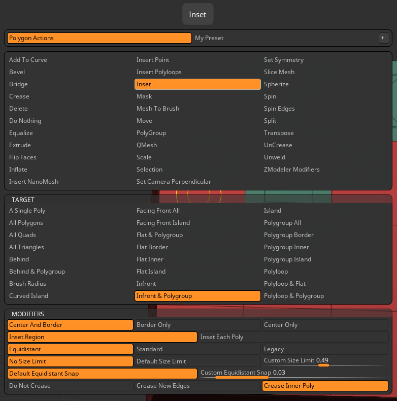
Modifiers
- Center and Border, Border Only, Center Only: Define how the new polygons are created. Center and Border will generate the inset polygons plus any polygons that are needed to connect them to the original edges. Border Only will not create the center polygon, while Center Only will not create border polygons.
- Inset Each Poly, Inset Region: Define whether every polygon within the Target receives its own inset or if the Target polygons are treated as an entire region with a shared inset. (This latter option effectively results in an edge loop.)
Alternative Operations
- Alt: Change the PolyGroup of the inserted part.
- Shift: Change the shape of the inserted polygon(s) to be square rather than proportional to the original polygon/region.
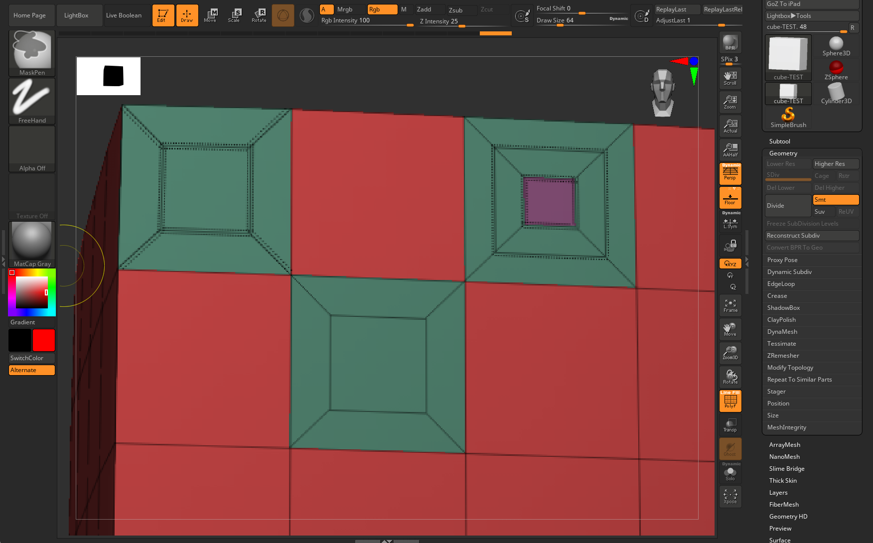
Note the bottom three options in the QuickMenu: Do Not Crease, Crease New Edges, and Crease Inner Poly. You see all three of these illustrated below. The lowest inset has only thin edges, the tell-tale for Do Not Crease. The top-left inset has all thick edges, the hallmark of crease lines, marking that as Crease New Edges. Finally, the top-right inset has regular edge outer lines, but the inner poly is comprised of creases, thus making it Crease Inner Poly. And just for fun, we used the same setting to make a smaller Crease Inner Poly inside the larger one, just to show how the feature repeats.
Mask
The Mask Action simply masks the clicked polygon or selected Target, preserving it from manipulation until the mask is cleared.
Clicking on multiple items is possible, letting you protect as many polys as needed.
Mesh to Brush
The Mesh to Brush Action converts the Target geometry to a NanoMesh brush, ready for applying later as a NanoMesh.
Modifiers
- Align to Mesh Orientation, Align to Clicked Face Normal: Define the orientation of the mesh when it is stored within the brush. When working with the Align to Clicked Face Normal modifier, it is advised to switch to orthogonal view and carefully select the camera position.
Move
The Move Action lets you manipulate the Targeted polygons as specified by the two modifiers. All polygons are moved the same distance, without any falloff effect, deformation,or snapping.
Modifiers
- Align to Normal: Sets the Target to move along the normal of the clicked polygon (perpendicular to the surface).
- Align to Axis: Sets the Target to move based on the nearest world axis with the screen working plane (user point of view).
Polygroup
The Polygroup Action generates new PolyGroups for the Targeted polygons. Because ZModeler makes extensive use of PolyGroups for Targets, this Action can quickly becoming one of go-to items for creating a faster workflow.
This Action has no impact on your mesh’s topology; it only changes the existing PolyGroup(s).
Don’t forget to refer to the Working with PolyGroups chapter of the ZModeler documentation for more information about how to use PolyGroups, including how to work with ZModeler’s Temporary PolyGroup feature.
Options
- One GroupID: Creates a unique PolyGroup.
- Three Sides: Creates different PolyGroups for each world working plane. (X, Y, Z)
- Six Sides: Creates different PolyGroups corresponding to each side of the world’s working planes. (+X, -X, +Y, -Y, +Z, -Z)
- Topological: Creates gradient PolyGroups that follow the mesh topology, based on the initial click location.
- Poly Order: Creates PolyGroups based on the polygon order.
- Point Order: Creates PolyGroups based on the point order.
- Relative Plus, Minus One: Replace the existing PolyGroup with a slightly different hue.
- Checker: Create two PolyGroups with a checker pattern.
Modifiers
- Overwrite, Additive: Define how new PolyGroups are created. Overwrite applies a new PolyGroup and uses it for each subsequent click while the Additive modifier creates a different PolyGroup with each click.
- Pick Existing: Copies the PolyGroup of the clicked face and stores it for use with the next PolyGroup creation process.
- Full, Random Coverage: Apply the PolyGroup to either the entire Target region to a fraction of it.
QMesh
The QMesh Action lets you click and drag to extrude the Target polygons.
By default, the QMesh operation is exactly the same as the Extrude Edge Action, except that:
- The created mesh will attempt to fuse to the adjacent polygons.
- The created mesh can be completely deleted by performing a negative extrusion.
The attraction of the fusing operation depends upon the Draw Size: a small brush size will trigger a strong fuse operation while a larger brush size will apply weaker fusing.
The position of the cursor when clicking on the Target edge will define the direction of the extrusion. It is important to carefully position your cursor before executing the Action.
Options
- Align tenth, Quarter, Third, Half, Full Step, No Alignment: Define the number of steps that the QMesh extrusion will have between the clicked polygon and its maximum height. These Modifiers have no effect when the extruded polygon doesn’t come in contact with adjacent polygons.
Modifiers
- One Side Poly, Multi Sides By Brush, Step Size: One Side Poly is the default fuse function of QMesh. The Step Size Modifier will allow you to perform a continuous Qmesh of the clicked polygons, generating edge loops along the length equal to the Draw Size or a defined value.
- Normal Attraction, Weak Attraction, No Attraction: Define the sensitivity of the fusing detection.
- Disable and Enable Triangle Snap: When enabled, QMesh will allow the fusing operation to create triangles.
- Disable and Enable Extended Snap: When enabled, snapping continues beyond the full step of the extrusion. If the Step is set to quarter, then it will continue to add a step equal to a quarter of the distance beyond a full step. When disabled, ZBrush will snap to the maximum distance of the surrounding polygons without needing to evaluate height.
Alternative Operations
- Ctrl: Stops the extrusion process and switches to a Move Action.
- Shift: Disconnects the polygons adjacent to the extrusion.
- Alt: Changes the PolyGroup of the extruded part.
Scale
The Scale Action scales the Target polygons. When scaling a single polygon, ZBrush will simply move its points in or out relative to the anchor point defined by the options. When scaling a poly loop, ZBrush may scale a larger part of the model as determined by the path of the poly loop.
Options
- Mesh Center, Axis Center, Local Symmetry, Click Center, Polygon Center: Define the location of the anchor point for the scaling operation, with all affected points moving relative to it.
Selection
Polygon selection allows you to quickly assign temporary polygroup selections, making it easy to multi-select and apply a single action to multiple polygons.
• Clicking polygons highlights them with a white polygroup, enabling manual assignment of Polygon Actions.
• To clear all selections, double-click any selected polygon.
When not using the polygon Selection action, you must hold the Alt/Option key for temporary polygon selection. When using Polygon Selection, the Alt/Option modifier is not needed.
Spherize
The Spherize Action forces the Target polygons toward a spherical shape. Moving the stroke in different directions while clicking and dragging generates different results.
Alternative Operations
- Shift: Spherize by moving all affected vertices at the same time.
Spin
The Spin Action rotates the Target polygons around a point defined by the selected option.
Options
- Mesh, Axis, Polygon, Clicked Center, Local Symmetry, Clicked Polygon Corner: Define which point the polygon(s) will spin around. Some rotation centers are defined by the topology while others are determined by the click position.
Modifiers
- No Alignment, Align to 15 Degrees, Custom Alignment: Set a constraint value that affects the rotation of the spin Action.
- Align Rotation to Axis: The rotation is done along the closest world axis.
Spin Edges
The Spin Edges Action changes the point order within the clicked Target. The usage is specific to those functions in ZBrush which make use of point order, such as MicroMesh and NanoMesh.
Because this only affects point order rather than position, you won’t see any apparent effect unless you have applied a NanoMesh or MicroMesh to the surface. With one of these functions applied, performing the Action will change the orientation of the NanoMesh or MicroMesh.
Options
- Clockwise, Counter Clockwise: Define the rotation direction.
Split
The Split Action inserts a point in the clicked polygon and connects it to middle of each surrounding edge. This Action is similar to Insert Point but maintains a quad surface.
TransPose
The Transpose Action automatically masks everything except the selected Target and then switches to TransPose Move mode to manipulate the surface standard TransPose operations.
Please keep in mind that while using TransPose, you are no longer in Draw mode. You have to switch back to Draw mode if you want to continue using ZModeler.
Unweld
The Unweld Action disconnects the Target polygons creases the border edges so that they maintain their shape when smoothed. Extruded polygons are created to keep the original shape visually unwelded when using Dynamic Subdivision mode.
The Unweld Action doesn’t split the model in multiple SubTools; it just disconnects the topology.
ZModeler Modifiers
There are a few settings which are universal ZModeler’s Actions and Targets. Modifying these are only necessary for very specific purposes.
- Default Flatness and Flat Targets Tolerance: Define the accuracy of flat surface detection performed by some targets. Increasing the value can allow Actions to affect slightly irregular areas and larger surfaces.