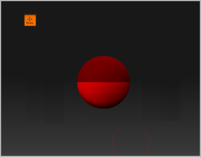
To start a ZSphere model, select the zsphere tool from the Tool palette – it’s the two-toned red ball – and draw it on the canvas. Enter Edit mode by pressing T on the keyboard.
The zsphere is two-toned so that it’s clear which way is up. In general, the dark red side should face normal (face the user). The line is the X-Axis.
The root (first) ZSphere has no geometry of its own. It is only a placeholder. You cannot delete the root ZSphere. You must attach a ZSphere at each end of the “root” sphere to “cap off” the geometry.
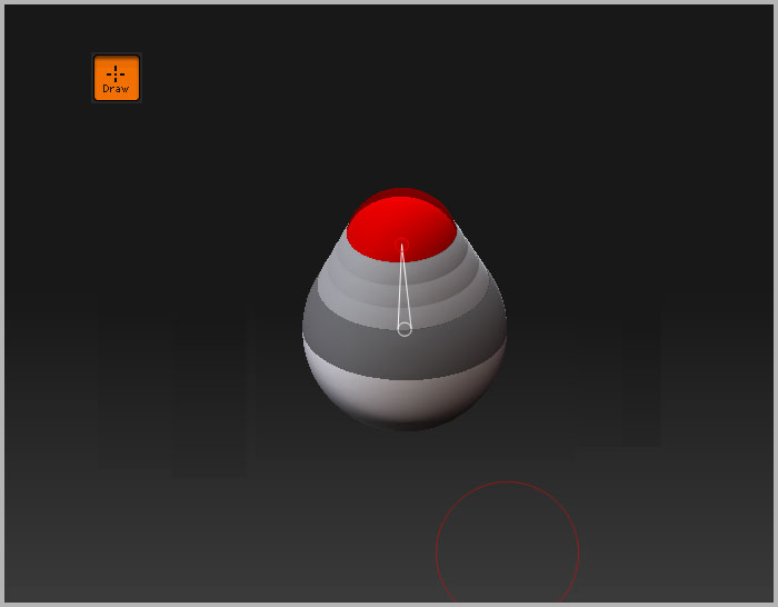
ZSpheres are added in Draw mode – press ‘Q’ on the keyboard if necessary. Then click and drag on the zsphere to add a new zsphere. Keep dragging until it’s the size you want.
Start dragging then press Shift to add a zsphere at the same size as its parent (the zsphere it is being added to).
Hold down Ctrl and continue to drag and the new child ZSphere will move away from its parent.
For a macro to scale ZSphere to the Draw Size see here: ZSpheres to Draw size .
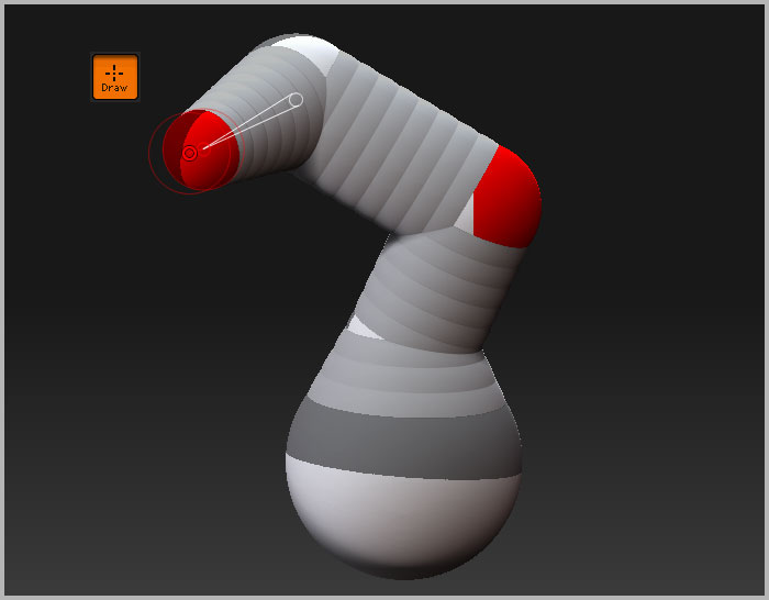
Each ZSphere, other than the root ZSphere, must have a parent. In addition, ZSpheres can have only one parent. Thus, the only way that two ZSpheres can be joined is if one of the ZSpheres is a child of the other.
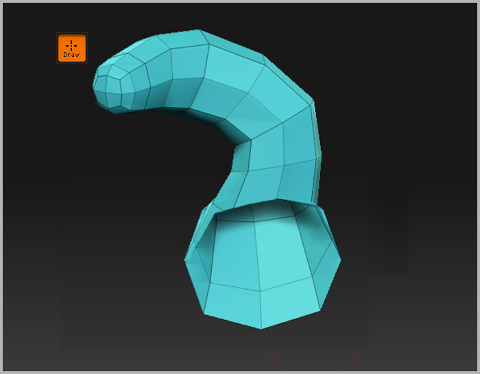
You can preview the mesh at any time by pressing A on the keyboard.
ZSpheres look round, but for purposes of skinning they are actually treated as cubes. Children should be attached to one of the faces of the cube. If you attach to a corner, you may get the results that you might expect. The easiest way to ensure that you attach in a good place is to turn on at least one axis of symmetry. Whenever the dots merge and turn green, you’ve got an ideal placement along one of the ZSphere’s axes (the center of one of the “cube’s faces”).
Obviously not much of a model can be created by simply adding zspheres to each other; some moving, scaling and rotating is necessary. Click the links below to learn more: