Object
Specifies the light type.
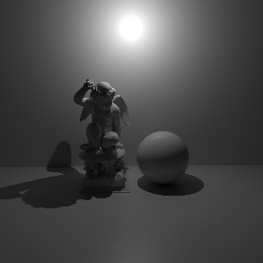
- Point: A point light. Simulates a 'bare bulb' light which emits light in all directions from an infinitesimally small point in space.
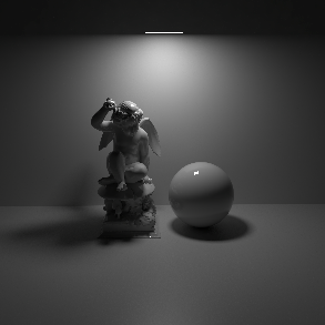
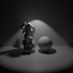
- Spot: A spot light. Emits light in a cone-shape.
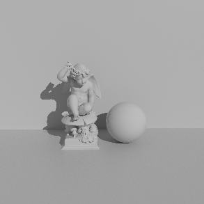
- Infinite: Simulates a light source which is infinitely far away from the scene. An infinite light has no position, only a direction. Therefore all light rays emitted are parallel and have no decay.
- Area: A light which has a real physical size and shape. Also offers an option to asign a geometry to be used as a light source (Mesh light).
- Dome: Simulates light emitting from a large sphere that always surrounds the entire scene. You can think of this as a sky that illuminates your objects and that can also be mapped with an image, for example. The dome light can thus also be used like a Cinema 4D Sky object.
- Photometric IES: Allows to load an IES Profile files to control the amount and direction of emitted light.
- Portal: A special type of light source that can optimize the calculation of global illumination. Often used in window frames for interior renderings to optimize the rendering of indirect light coming through the windows.
- Physical Sun: Similar to the Infinite light, but specially designed to mimic sunlight, including a color change depending on the angle of incidence of this light source.
|
|
|
|
|
| Light Type: Area | Point | Spot | Infinite |
Introduction to Dome lights
Dome lights cannot be combined with environment shaders. If the scene or any material uses environment shaders, the Dome light will override them.
The Redshift Dome light is an infinite, texture-mapped area light. Using HDR images you can achieve high-quality lighting results that would otherwise require several lights. Since a single Dome light can reproduce the lighting of several distant lights, it can help with performance, too. Furthermore, given that the HDR image can originate from a real-world environment, the dome light is an important tool to match the lighting of cg elements with live-action elements.
Introduction to IES lights
IES stands for Illuminating Engineering Society. The IES data format describes the distribution of light from a point source. Most major manufacturers of lights provide IES profiles which can be downloaded for free. Redshift IES lights use IES profiles to define the light's intensity and distribution. Below are some examples of different IES light profiles, note their drastically different light distribution patterns.
Introduction to Portal lights
When using a Portal light, make sure that the Z-axis of the portal is directed towards the interior, as the ambient light is emitted only along the positive Z-axis of this light.
A Portal Light is a rectangular Area Light used to assist in indoor Global Illumination. It acts a virtual window, casting direct lighting into a room from the environment outside. Portal lights effectively give you one bounce of 'brute force' Global Illumination for 'free'. If you were to just model a transparent window, you would need up to 4 times the amount of 'brute force' Global Illumination rays to achieve the same noise-free lighting, which of course would have a negative impact on performance. The Portal light blocks and absorbs Global Illumination rays. It works by sampling light color from the RS Environment shader, either from the Default Environment (see Redshift Render Preferences/Globals/Options) or the Custom Environment link of the Portal itself (by asigning RS Environment Materials). The following images show a typical use case.
The rendering of the interior appears almost completely black with only a slight red cast from the sunset HDRI used. After we place a Portal light in the opening of the wall, the rendering looks quite different. The room now "sees" much more of the Environment outside and is illuminated more by it. The render time has remained almost unchanged.
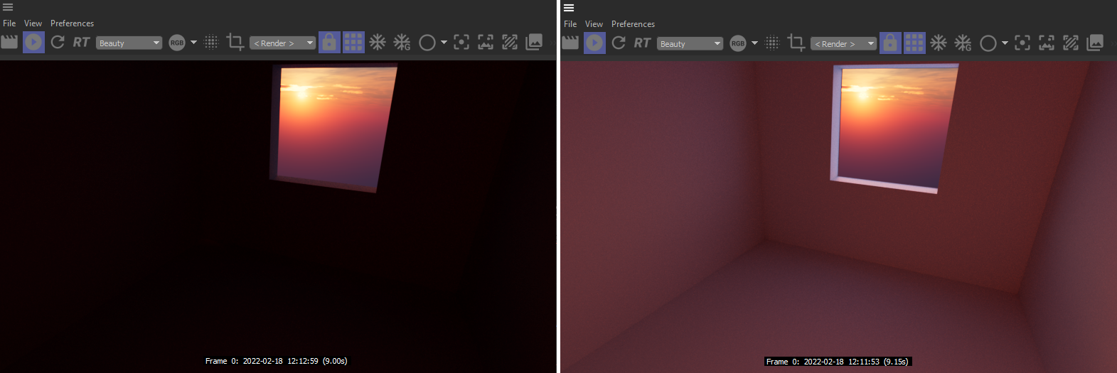
The left side shows the rendering without a Portal light, on the right side there is a portal in the open window.
Introduction to Physical Sun lights
The Redshift Physical Sun light offers a physically accurate representation of real sun-light. The Physical Sun is generally used in conjunction with the Physical Sky environment. Find out more about the Redshift Physical Sky here.
The color of this light source depends on its angle to the XZ ground plane. Lower light angles represent a sun near the horizon and warmer light colors. On the other hand, if the Z-axis of the light source points vertically downwards, this simulates a high noon sun and results in colder light colors. You can further refine this coloring with the following parameters.
Physical Sun emits light at an extremely high intensity (to model the physical intensity of sunlight that hits the Earth's surface) and you should therefore always use the Exposure settings at your Camera to achieve useful results when using Physical Sun. Without propper Exposure settings, the scene will likely render too bright or even completely white.
With the introduction of the new PRG Clear Sky model, the sun radiance is also now calculated from the dataset with known physical sun radiances in the visible light spectrum. The new sun radiance model is able to provide more saturated and strong lighting at sunset and an accurate radiance for direct lighting
Many settings of the Redshift light object can also be set through the material node system. Using this button will create a new Redshift Shader Graph material and connect it to this light.
Light parameters controllable by a light shader include the lights Color settings, Decay, Shadow options and Attenuation.
If a Shader Graph material has been asigned to the light, you can open the Redshift Shader Graph by using this button and edit the shader directly there.
Target commands
You can find these commands in a menu to the right of the Type menu. You can use them to add a Target expression tag to the light. By linking an object to that tag you can aim the z axis of the light to that object. Using the Add Target Tag and Null command creates an additional Null object and uses that as the Target Object with the Target expression tag.
In the Basic tab of the Redshift light object you can find an option to choose an individual Display Color. Activate this option to use that color also for the Wireframe preview of the light.
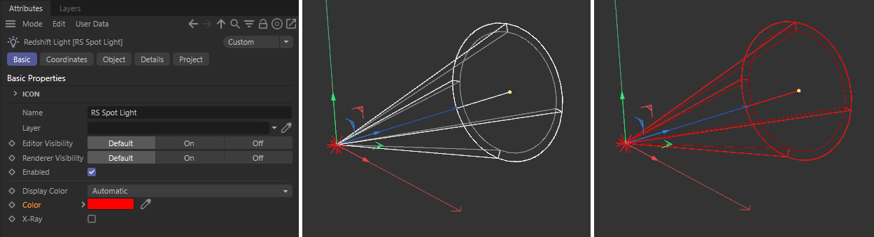 On the left side you can see how the light object has been assigned a red color. Without the "Blend Object Color" option enabled, only the spot's star icon in the viewport will be colored. If the option is enabled, the wireframe cone of the spot will also be colored, as you can see on the right side of the image above. However, this option does not change the color of the light for rendering.

Displays a wireframe representation of the light decay or light direction in the viewport. When this option is checked, some light types allow manipulation of certain parameters directly in the viewport.
Provides an approximation of the illumination of the light in the viewport.
Illumination Adjustment[0.00..+∞]
Adjusts the viewport illumination scale.
These options only affect the Cinema 4D viewport and have no effect in the IPR or when rendering.
Specifies the intensity of the light or the number of physical units (see Units setting below).
Specifies an f-stop value that allows you to intuitively increase/decrease the light's intensity when matching to a plate, or rendering large/tiny scenes without using hugh/miniscule Intensity multiplier numbers. A value of 0.0 means the intensity does not change.
For example, an Exposure value of 1.0 means the light doubles in intensity and a value by 2.0 means the light quadruples in intensity, etc.
Specifies the physical units to use for the light intensity.
- Image: use non-physical units.
- Luminous Power (lm): use lumens. The light intensity will not be affected by the area of the light.
- Luminance (cd/m^2): use candela/m^2.
- Radiant Power (W): use Watts. The light intensity will not be affected by the area of the light.
- Radiance (W/sr/m^2): use Watts/steradian/m^2.
Luminous Efficacy (lm/W)[-∞..+∞]
Specifies how many lumens are emitted per Watt. Only relevant when using Radiant Power or Radiance unit types.
- None
- Linear
- Quadratic
For physical correctness you must use the Quadratic Decay option.
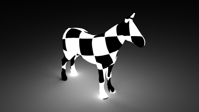
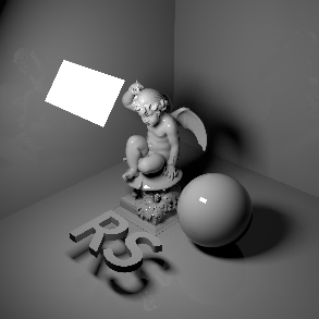
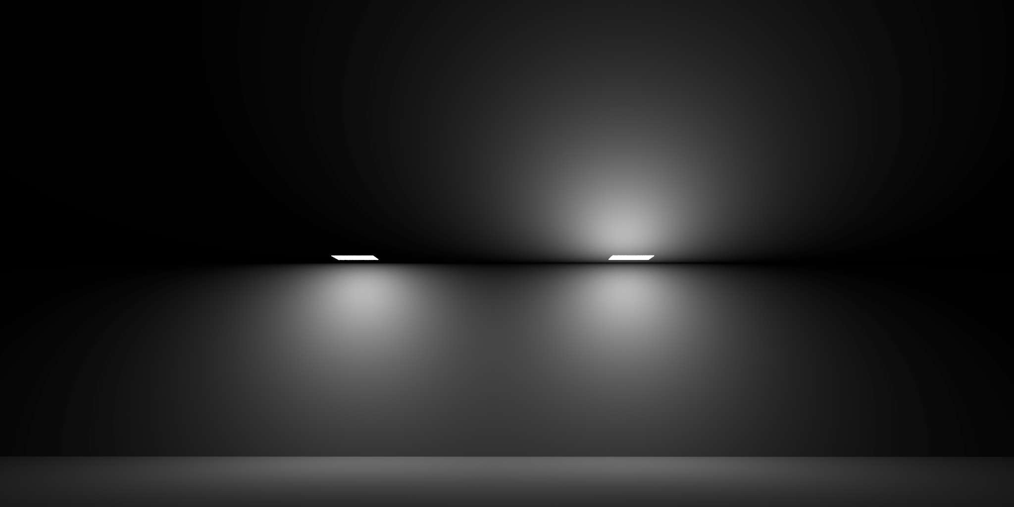
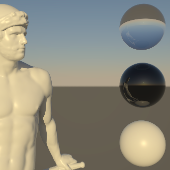
In the example below the light source in the bottom right has its Decay type switched between the 3 different types. Quadratic is physically accurate based on the light's size and intensity. Linear demonstrates how you can specify the start and stop falloff to control exactly where the light starts to be visible and then decays to nothing. None turns off Decay entirely.
|
|
|
|
| Decay Type: Quadratic | Linear | None |
Specifies the distance from the light at which Linear fall-off occurs.
Specifies the distance from the light at which Linear fall-off ends.
Specifies the color mode.
- Color: Light color is specified by the Color parameter below.
- Temperature: Light color is specified by the Temperature parameter below.
- Color and Temperature: Light color is specified by both the Color and the Temperature parameters below.
Specifies the color of the light by using the standard color chooser options.
You can load a bitmap image here to color the light and to use it like a projector.
When using an Area Light with an asigned Mesh geometry, you'll need to ensure that the referenced mesh contains a UV coordinate set. You can then texture your Mesh light just like you'd texture any other light: by connecting a Texture to the light's Color.
Specifies the color of the light using a color temperature value (in Kelvin). Redshift supports color temperatures between 1667K and 25000K. Lower values are 'warmer' or more red, while higher values are 'cooler' or more blue.
|
|
|
|
|
|
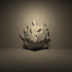
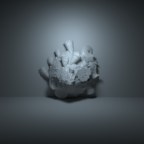
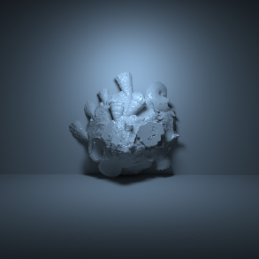
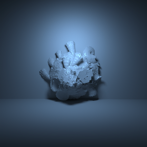
Temperature
Temperature mode demonstration ranging from low values resulting in warm tones on the left to high values resulting in cool tones on the right.
|
|
|
|
|
|
Color
Color mode demonstration ranging from reddish tones on the left to bluish tones on the right.
Specifies the physical shape of the area light;
- Rectangle
- Disc
- Sphere
- Cylinder
- Mesh
|
|
|
|
|
|
| Area Shape: Rectangle | Disc | Sphere | Cylinder | Mesh |
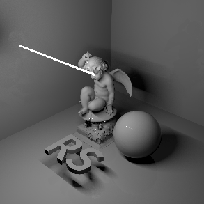
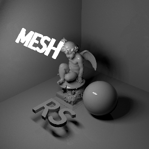
Here you can link to your geometry, that is then used to emit light.
Mesh lights can reproduce lighting emitted from complex shapes like a neon sign. While a similar result can be achieved with a combination of incandescent geometry and GI, that can be considerably noisier than Mesh lights.
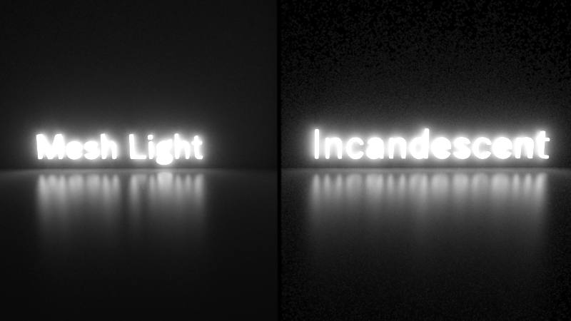
Using Mesh lights instead of incandescent geometry can produce less noise, especially on places that are far from the light.
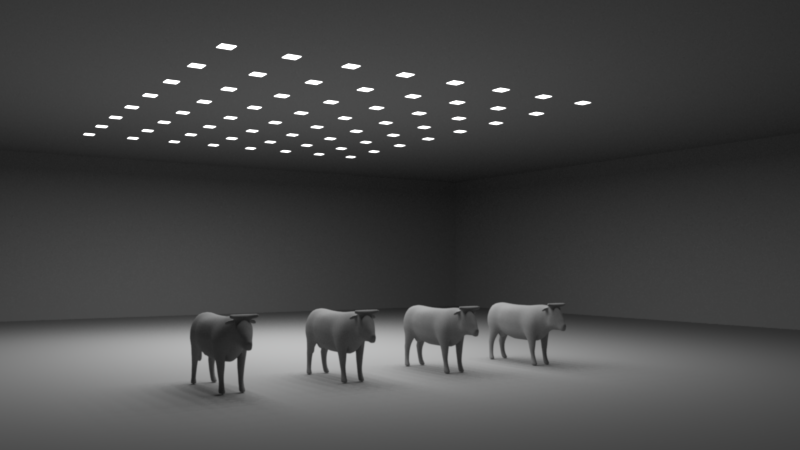
In certain cases, Mesh lights can also help optimize rendering times by facilitating the combination of multiple simple lights into fewer Mesh lights.
|
|
|
|
Scene with 64 rectangular area lights. Rendered in 11 seconds |
Scene with a single mesh light containing 64 quads. Rendered in 2.8 seconds |
It depends on you Area Shape choice if and how many of these settings you can access. Use them to scale the chosen shape.
Enables directionality control for Rectangle and Disc Area lights, similar to a barn door effect or spot light. The lower the Spread, the more the light is concentrated in the direction of the light normal. A Spread value of 1.0 is the default, physically correct lighting behavior, while a value of 0.0 makes the light a parallel light.
Note that a Spread of 0.0 is close to a fully directional light, but the light rays will not be perfectly parallel. This is due to a mathematical sampling limitation.
|
|
|
| Spread: 1.0 | 0.3 |
Controls the primary visibility of the light.
A visible light will block you from seeing through them both from the front and back. If a light is visible, it will cast shadows from other lights.
 The image shows a rectangular light with visibility enabled on the left and disabled on the right. Note that there is no difference in the light distribution here. However lights with visibility enabled will cast shadows from other lights in the scene.
Enables bi-directional lighting such that light is emitted on both sides of the shape. Only valid for Rectangle and Disc Area shapes.
 The image shows a rectangular light with Bi-directional disabled on the left and enabled on the right.Note how the light comes out of both sides with bi-directional enabled.
Removes the area of the light from the lighting calculation. Enabling this option prevents the light intensity from changing when the size of the light changes.
This is only accessable for a Spot light and specifies the angle of the spot light cone.
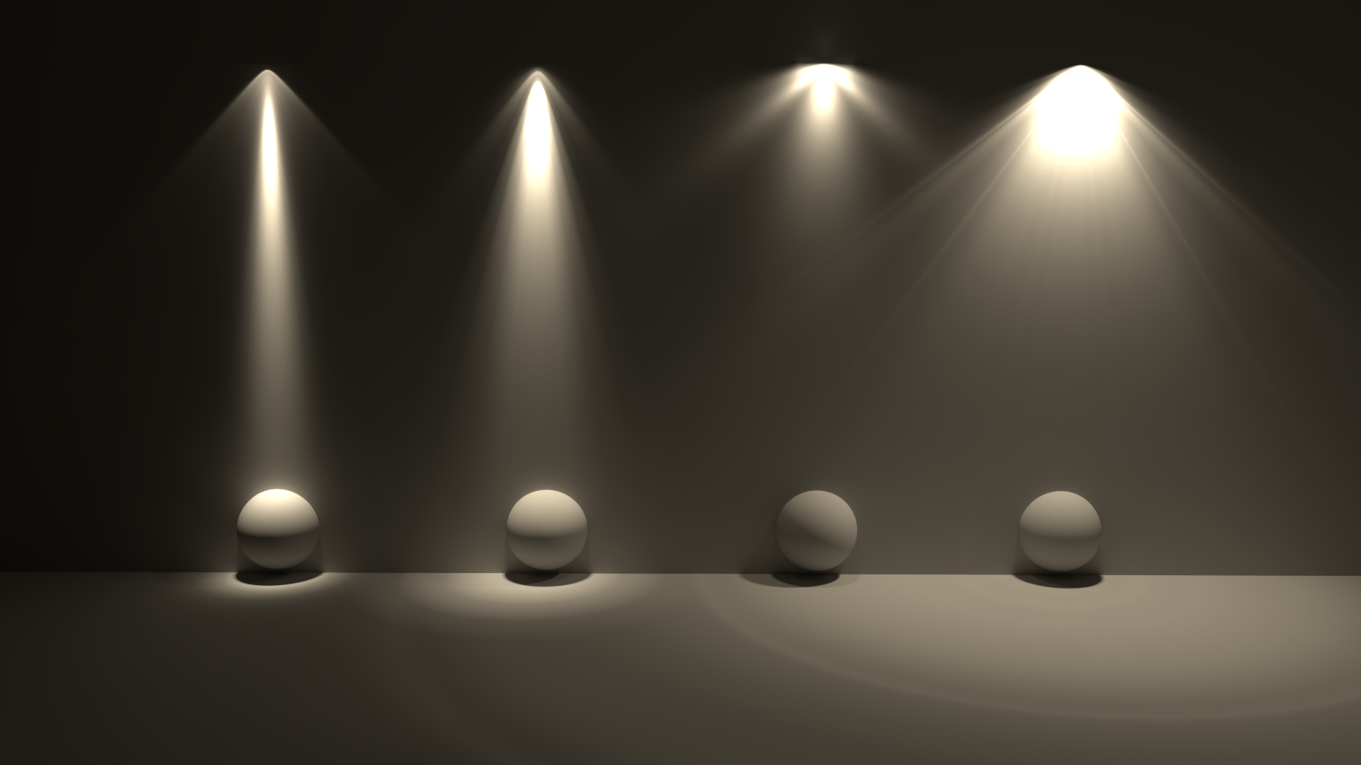
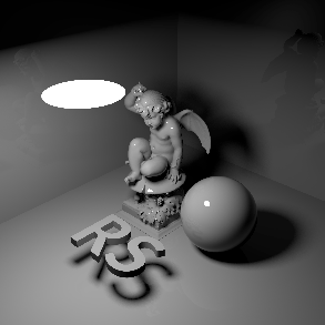
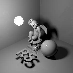
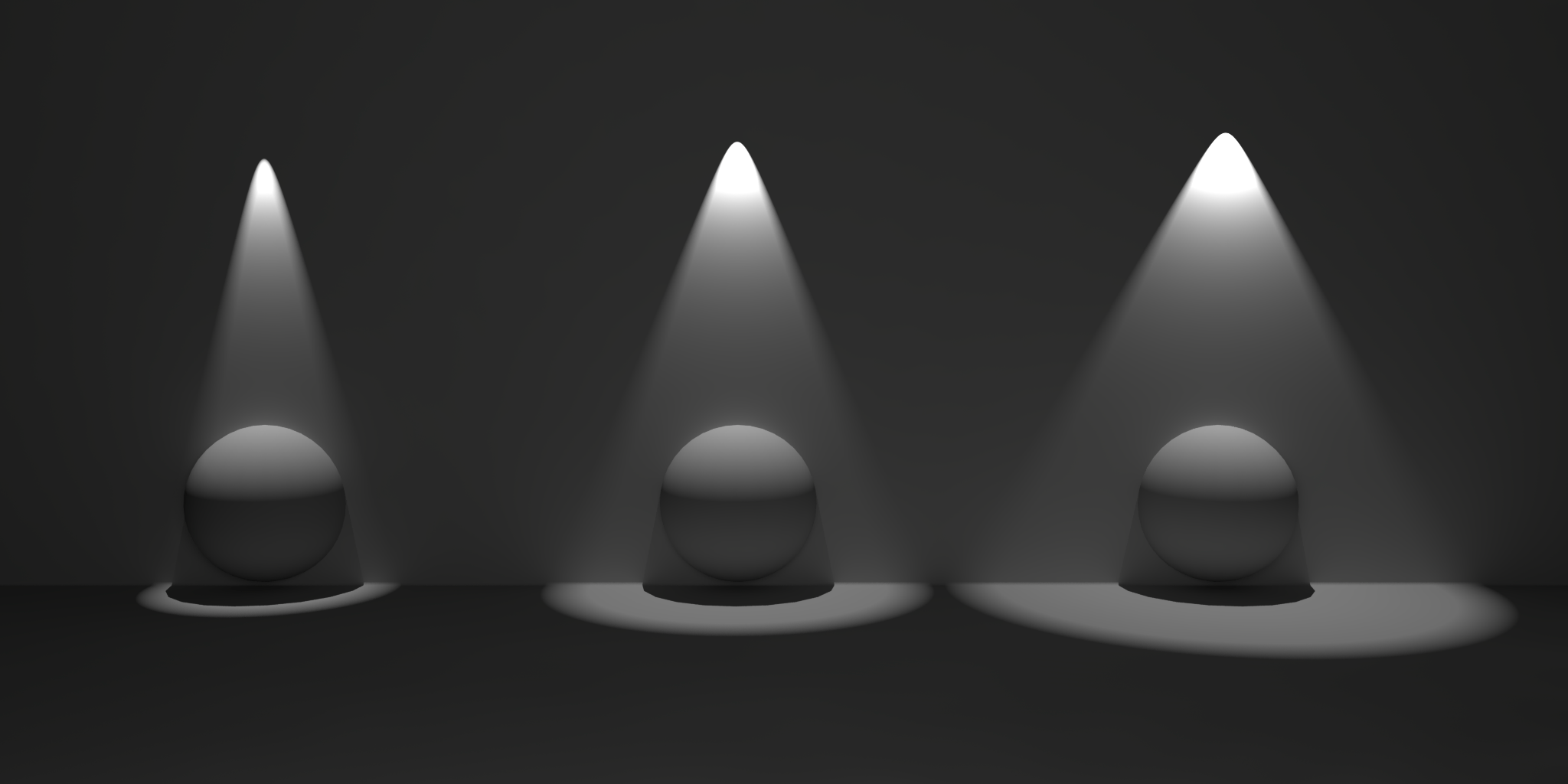
Below shows three physical lights set to Spot with cone angle values smallest on the left to largest on the right:
This is only available for a Spot and specifies the angle over which light falls off at the edge of the spot light cone. Smaller values will produce a sharper edge.
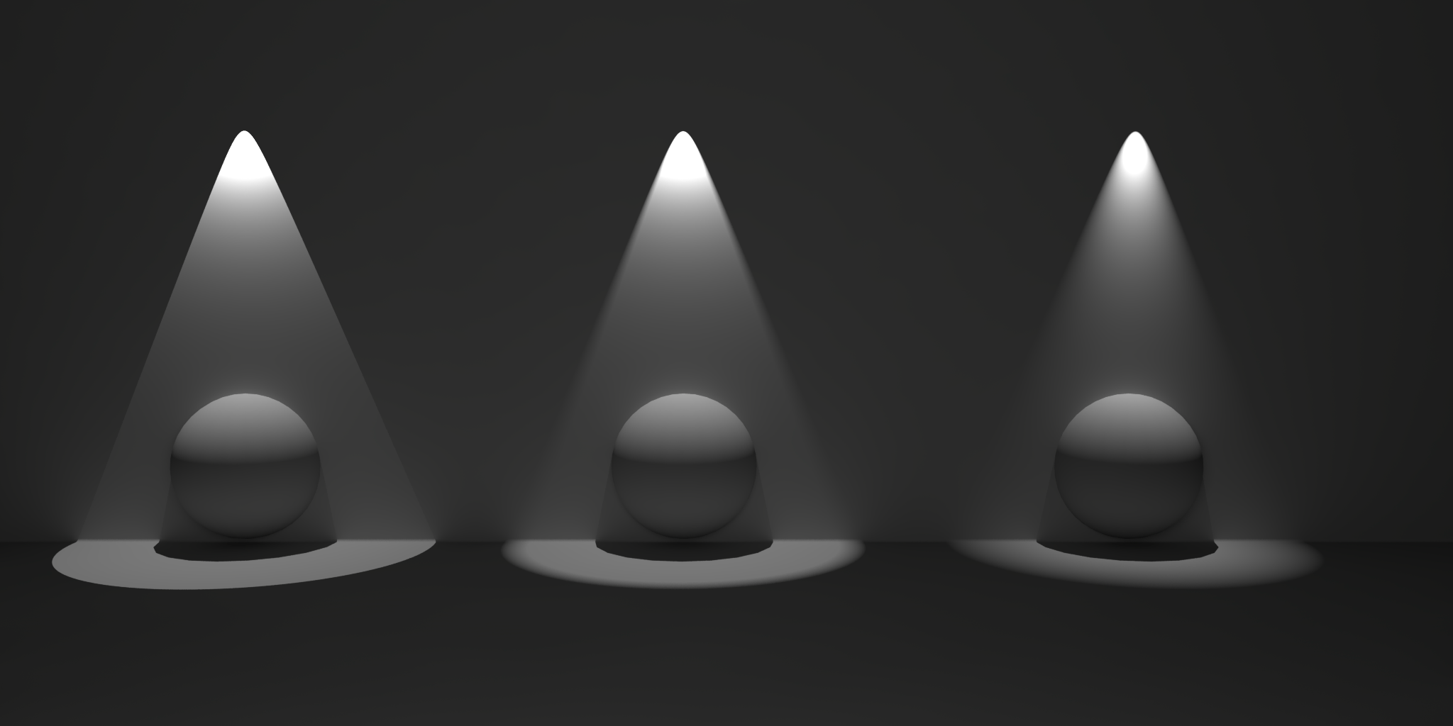
Below shows three Spot lights with Falloff Angle values smallest on the left to largest on the right:
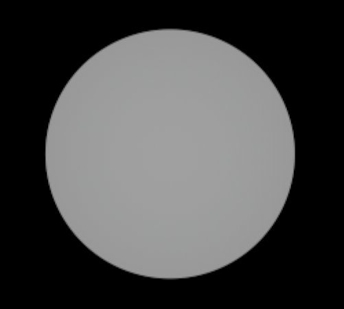
This is only available for a Spot and changes the light intensity distribution within the light cone. With increasing values the light intensity will decrease faster between the center and the outer border of the spot cone. The images below show a spot aiming straight at a wall. The only difference between the images is the value for the Falloff Curve.
|
|
|
| Falloff Curve: 0.0 | 50.0 |
These are the unique parameters for Dome lights.
Specifies the intensity or strength of the light..
Specifies an f-stop value that allows you to intuitively increase/decrease the light's intensity when matching to a plate, or rendering large/tiny scenes without using hugh/miniscule Intensity Multiplier numbers. A value of 0.0 means the intensity does not change.
For example, an Exposure value of 1.0 means the light doubles in intensity and a value by 2.0 means the light quadruples in intensity, etc.
|
|
|
|
|
Exposure (EV): 0.0 |
1.0 |
-1.0 |
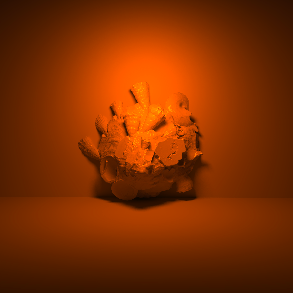
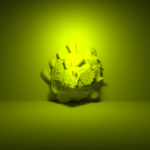
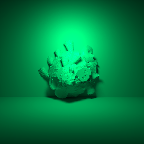
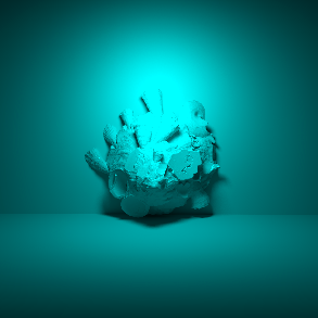
You can use this color not only for the light, but also to use as a visible background color, if the Background option is active. If you decide to load a Texture this color will get multiplied with the texture.
The closer your tint color is to white the less affected your light color will be. For a mild color tint be sure to use a desaturated color, a fully saturated color can fully tint all the colors in the scene as pictured below in the saturated green example.
|
|
|
|
|
Tint Color:
|
|
|
Specifies the image that will be used as a light source. The configured Color will be multiplied with this texture.
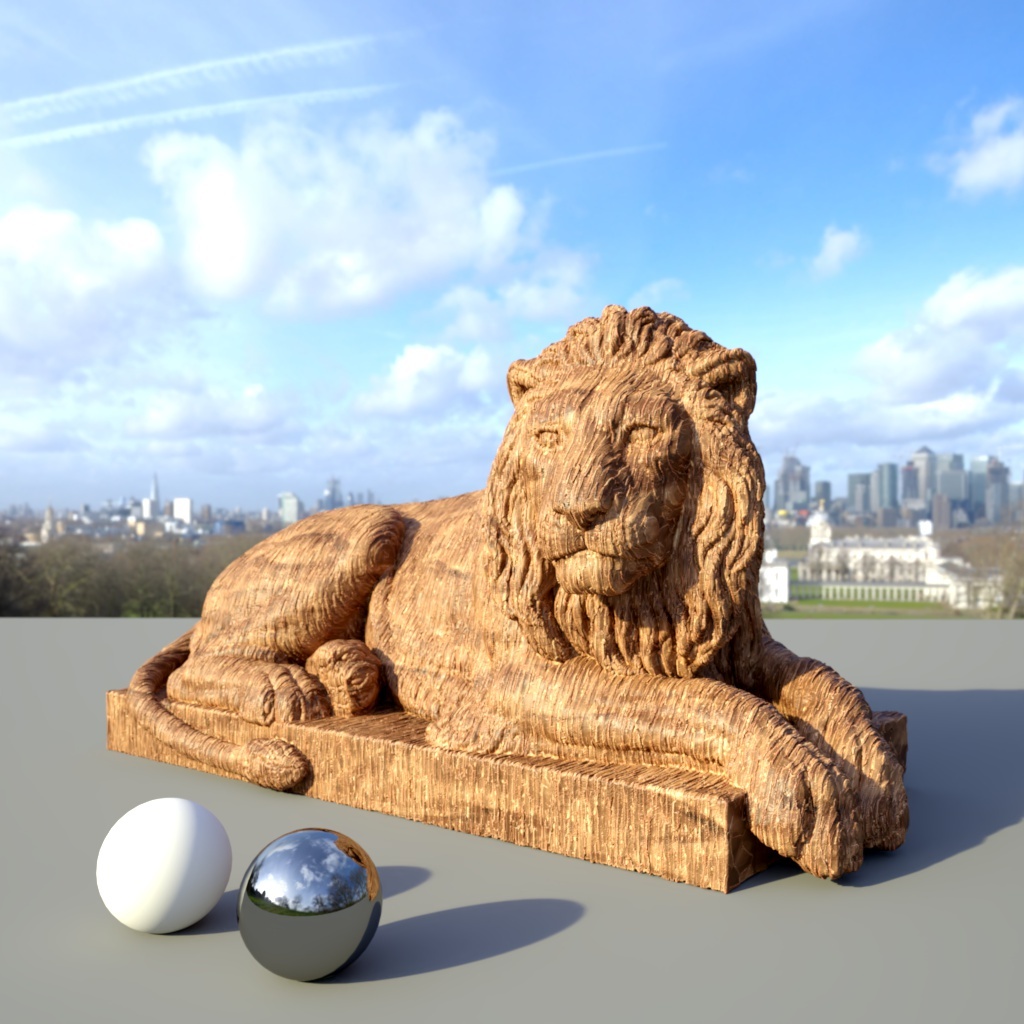
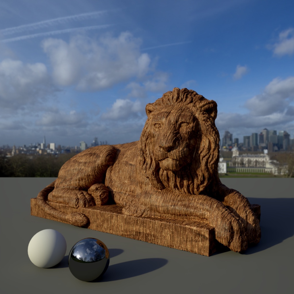
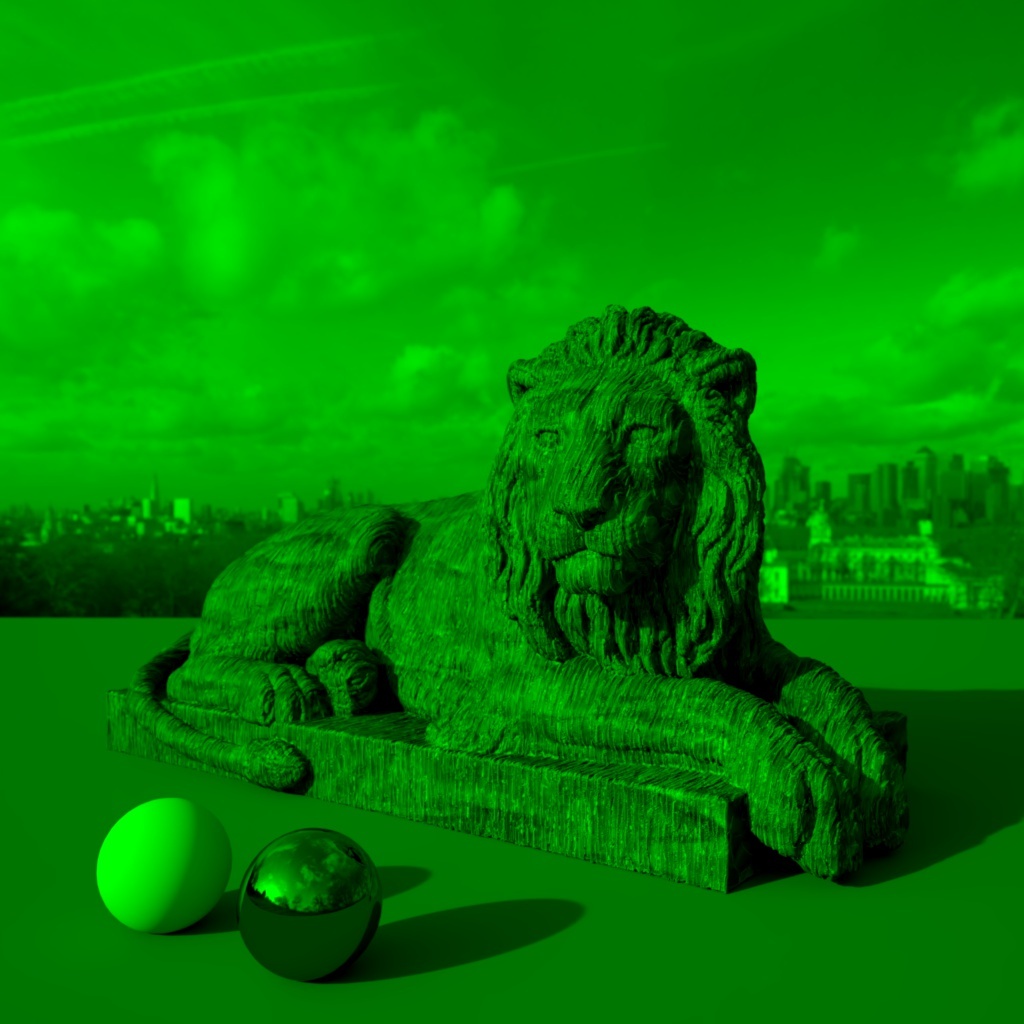
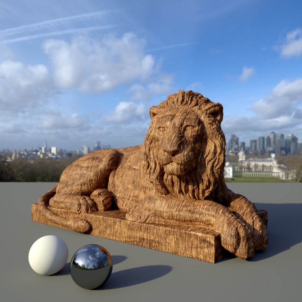
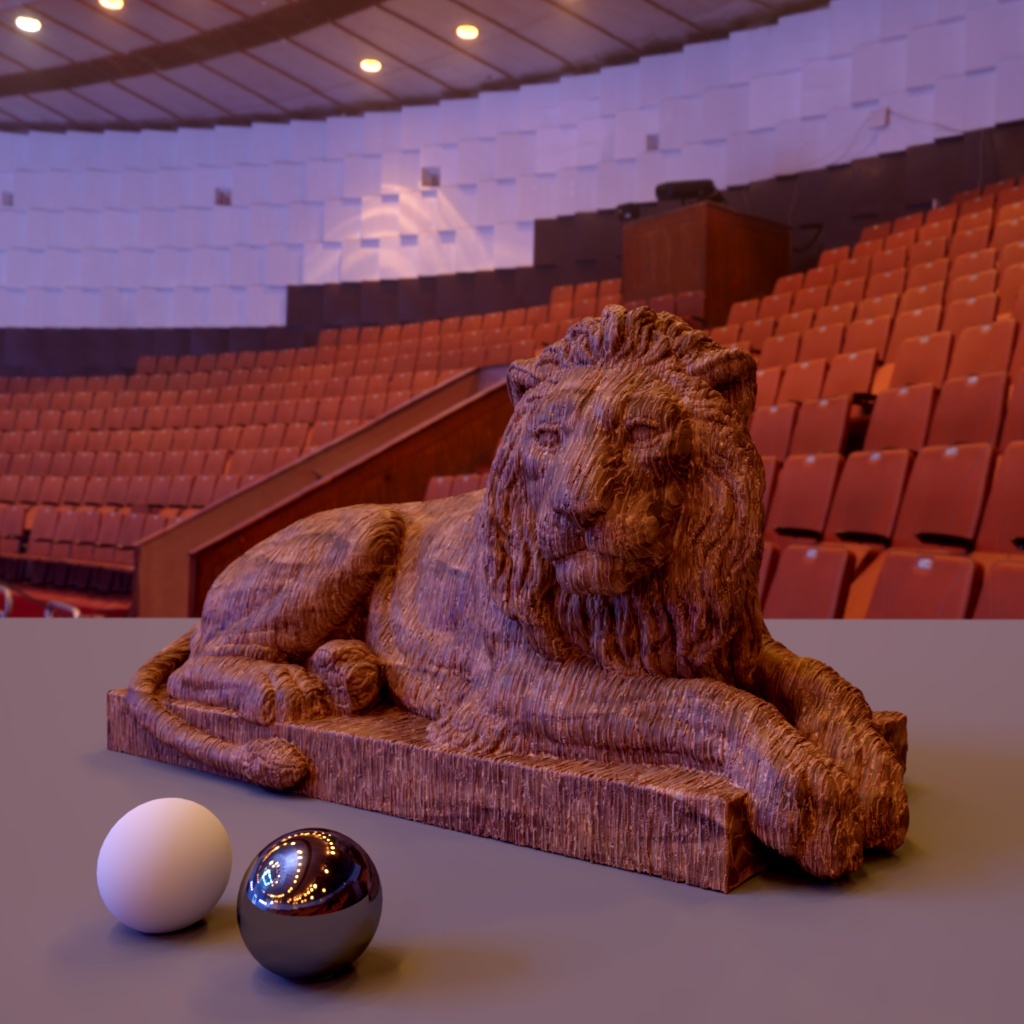
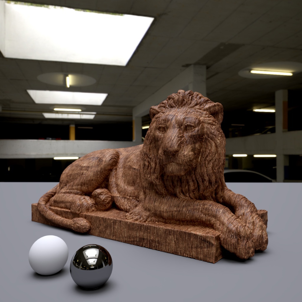
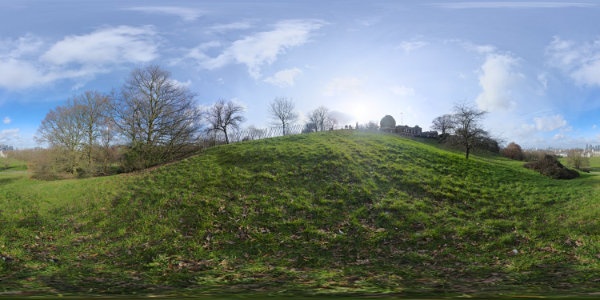
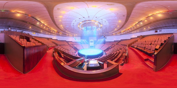
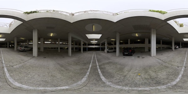
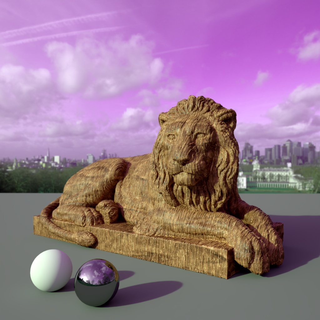
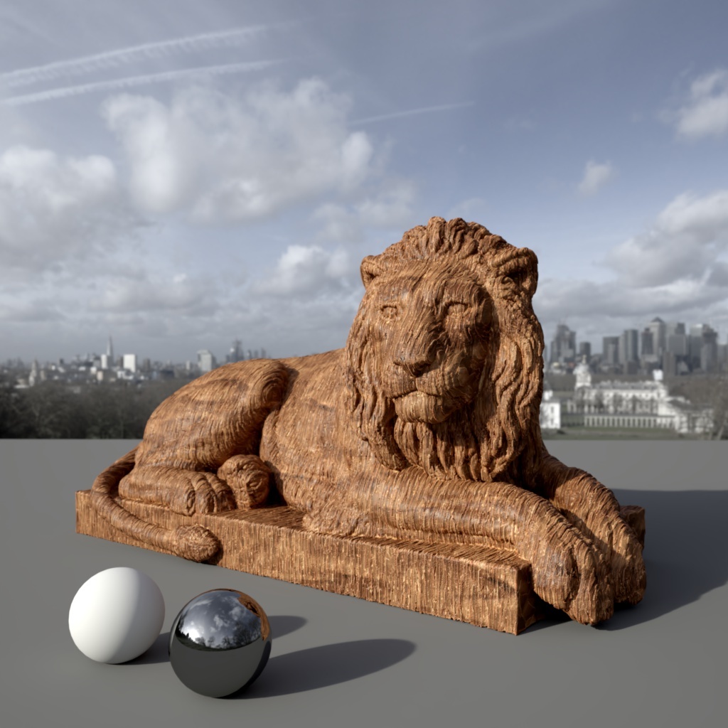
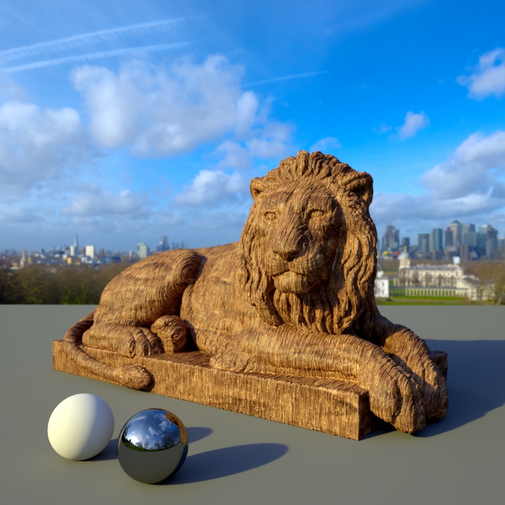
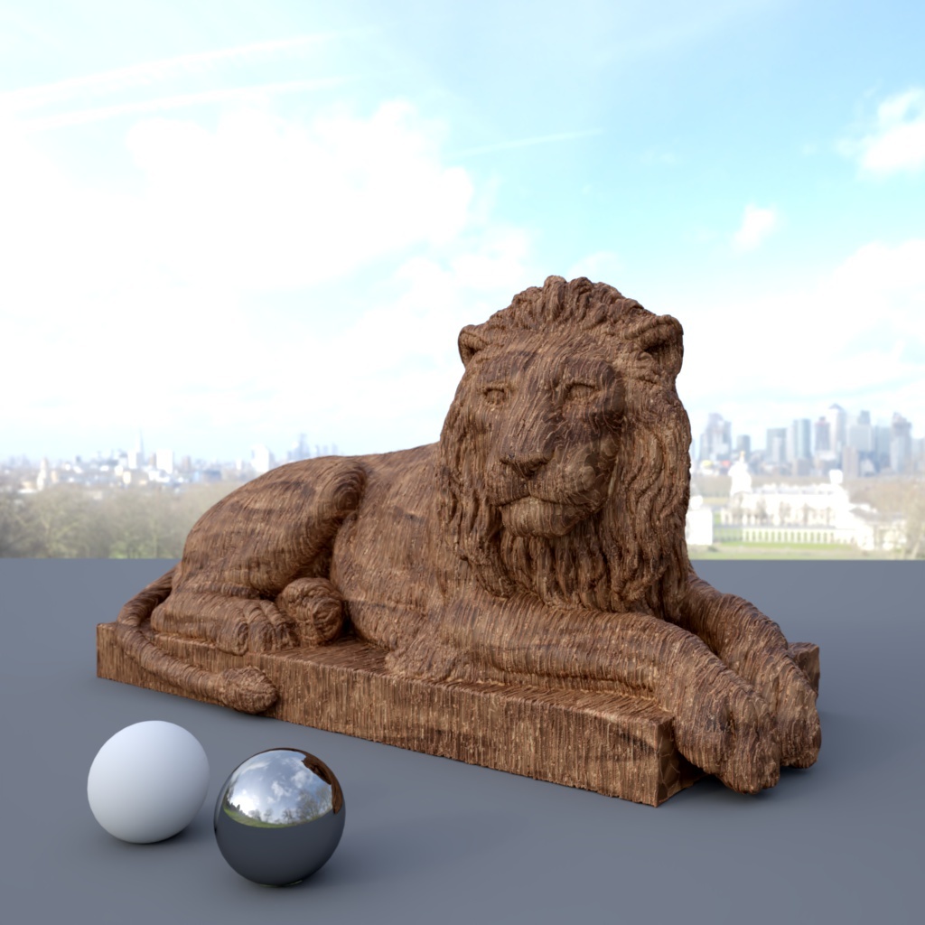
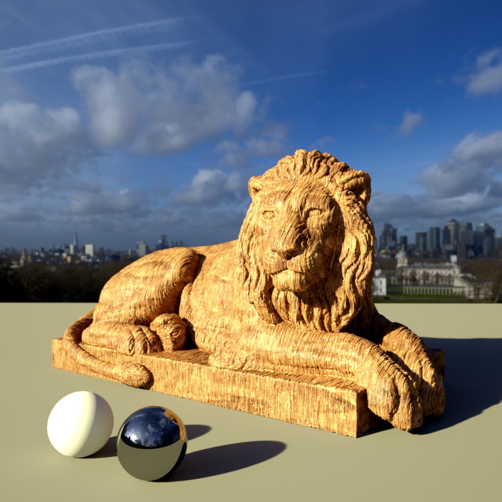
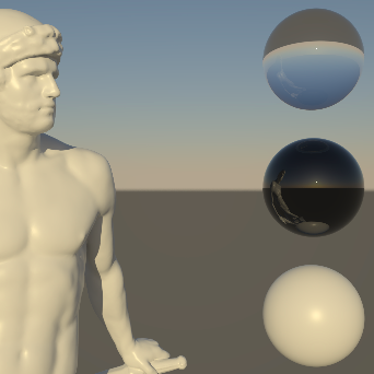
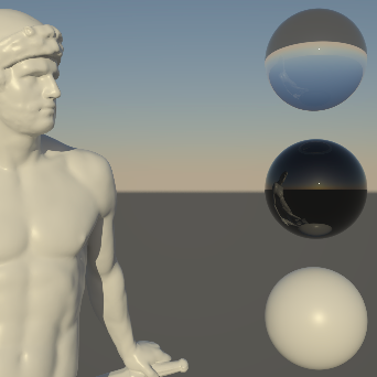
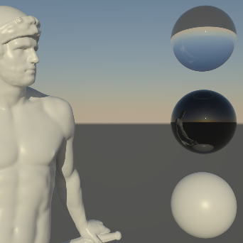
Below you can see the same scene lit with three different HDRI Dome maps with Background turned on.
|
|
|
| Texture: Greenwich Park | Circus Arena | Skylit Garage |
|
|
|
Example images use HDRI's from PolyHaven |
||
Perhaps the most important element of a Dome light is its texture map. Ideally, HDR textures in OpenEXR format should be used because they can capture a wide range of intensities. Such HDR can textures can either be obtained in the web or an application (like "HDR light studio") can be used to author them.
Here are a couple of important things to remember regarding the texture map:
- Very small, very bright spots on the texture map will produce sharp shadows
- Large spots will produce softer shadows
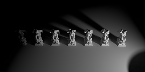
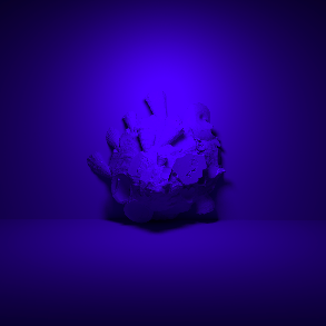
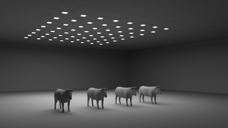
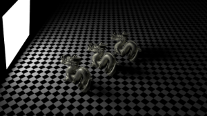
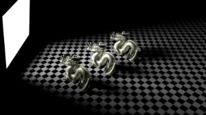
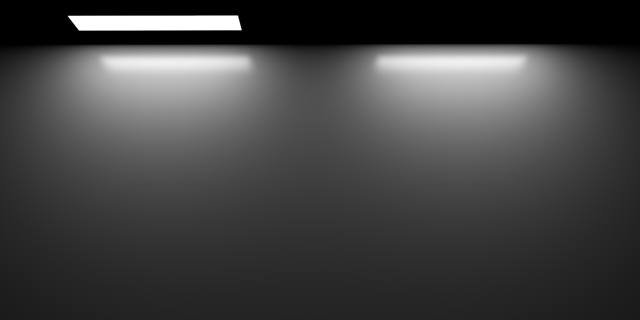
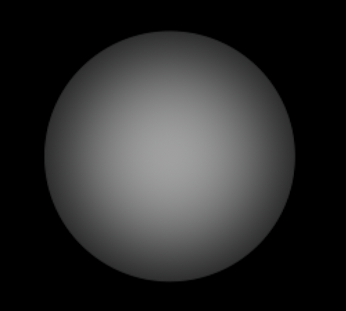
In a sense, the Dome light's texture features behave like area lights: large Area lights produce soft shadows while small Area lights produce sharper shadows. Below are a couple of shots demonstrating this. The left part of each image pair is the Dome light map and the second is the final rendered result.
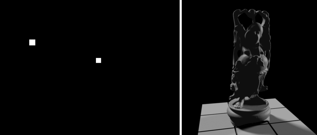 The Dome light texture map contains only two small boxes. This is not an HDR map and, because the boxes are small, they can produce very dark lighting results by default. To fix this issue, the dome light's Intensity parameter was set to 60. Because of the small bright boxes, the shadows on the final render are fairly sharp.
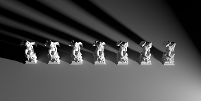
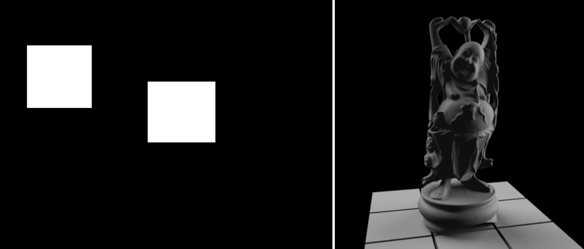 For the next example, the boxes were made bigger. The more brightness a dome light map contains, the brighter the lighting. For this reason the Intensity parameter was reduced to 2. As it can be seen on the final render, larger boxes create softer lighting.
Specifies the type of image that is used as the light source:
- Spherical: Sampled as a longitude/latitude full sphere map
- Hemispherical: Sampled as a longitude/latitude hemisphere map
- Mirror Ball: Sampled as a mirror ball map
- Angular: Sampled as an angular map
Some renderers use a different convention for how a Dome light should wrap around the virtual world in the X axis. The Flip Horizontal option, as the name suggests, flips the loaded texture on the Dome light in the X axis to help match the look of a different renderer.
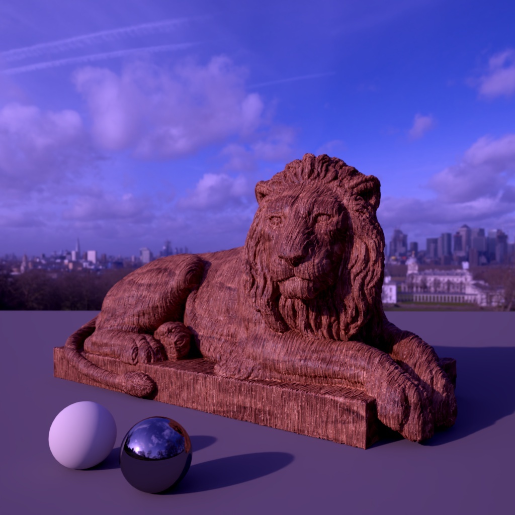
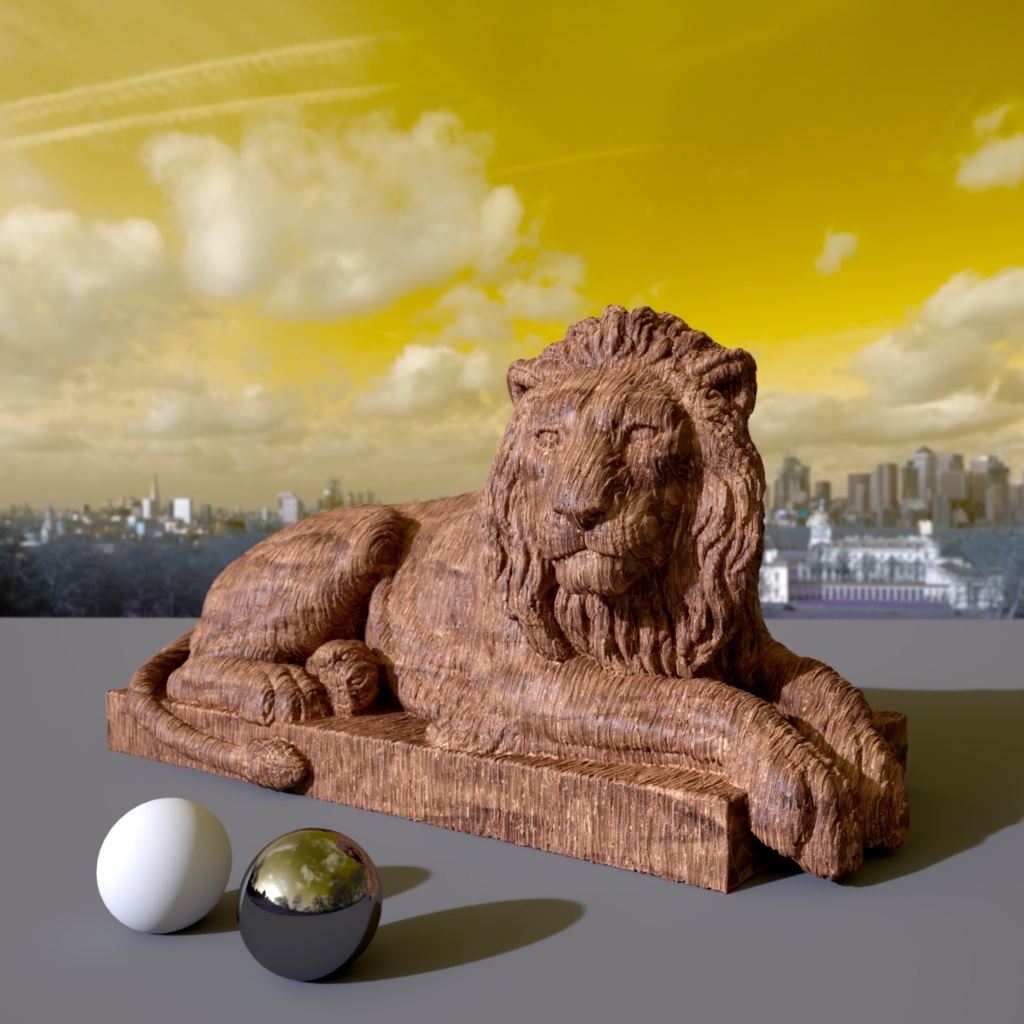
You can use this value to shift the colors used in the loaded texture. If you just like to color the loaded Texture, you can use the Color instead.
|
|
|
|
|
Hue: 0.0 |
60.0 |
180.0 |
This is a percentage value, so 100 results in the full saturation of the loaded Texture being used. Since this Saturation only applies to the loaded Texture, you can still use the Color setting of the light.
|
|
|
|
|
Saturation: 100 |
30 |
170 |
This setting sets the gamma value for your Dome image map. Higher values can help increase contrast in the Dome map while lower values reduce contrast. Depending on your Dome map adjusting Gamma can help to adjust your scenes lighting when you want sharper or softer shadows.
In the examples below the exposure has been adjusted slightly to counteract the gamma change.
|
|
|
|
|
Gamma: 1.0 Exposure (EV): 0.0 |
0.5 1.0 |
1.2 -1.0 |
These parameters are specific for Dome lights. Additional options to use a background image can be found a the Redshift Camera Object.
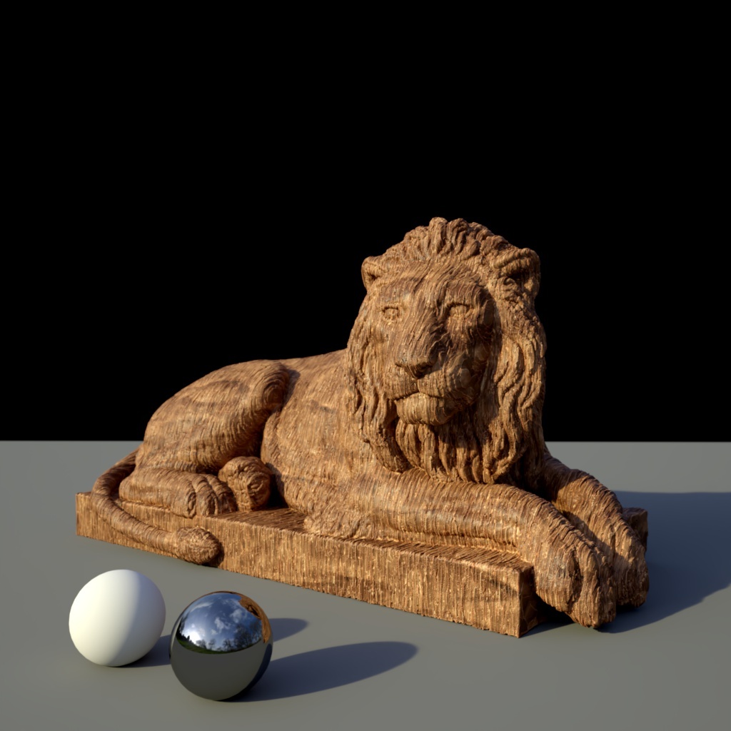
When enabled this setting will render the Dome light Texture or the plain Color as the background in your render.
|
|
|
|
Enable Background: Enabled |
Disabled |
These settings are specific for IES lights.
Specifies a multiplier for the light intensities described in the IES profile. This parameter allows you to scale the IES intensity up or down.
Specifies an f-stop value to intuitively match the light's intensity to a plate or rendering scenes without using extremely large or small Intensity values. A value of 0.0 means the exposure parameter does not alter the lights intensity.
For example, an Exposure value of 1.0 means the light doubles in intensity and a value by 2.0 means the light quadruples in intensity, etc.
Specifies the color mode.
- Color: Light color is specified by the Color parameter below.
- Temperature: Light color is specified by the Temperature parameter below.
Specifies the color of the light when Mode is set to Color.
Specifies the color of the light using a color temperature value (in Kelvin) when Mode is set to Temperature. Redshift supports color temperatures between 1667K and 25000K. Lower values are 'warmer' or more red, while higher values are 'cooler' or more blue.
IES stands for Illuminating Engineering Society. The IES data format describes the distribution of light from a point source. Most major manufacturers of lights provide IES profiles which can be downloaded for free.
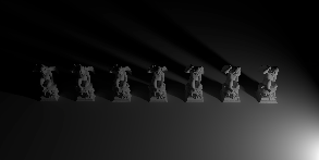
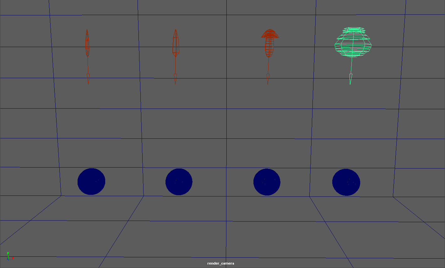
Redshift IES lights use IES profiles to define the light's intensity and distribution. Below are some examples of different IES light profiles, note their drastically different light distribution patterns.
Redshift automatically creates a simple geometric shape in the viewport that roughly illustrates the IES light's distribution pattern. Below you can see the viewport of the same scene, note how the viewport shapes below mimic the light cast in the example above.
These parameters are specific for Portal lights.
Specifies a multiplier for the intensity of the light cast by the portal.
Specifies an f-stop value that allows you to intuitively increase/decrease the light's intensity when matching to a plate, or rendering large/tiny scenes without using hugh/miniscule Intensity Multiplier numbers. A value of 0.0 means the intensity does not change.
For example, an Exposure value of 1.0 means the light doubles in intensity and a value by 2.0 means the light quadruples in intensity, etc.
These parameters are specific for Portal lights.
Specifies a color with which to tint the environment samples. Tint Color only affects the color of the light cast from the portal, not the color of the portal itself when seen either directly by the camera or indirectly via reflections or refractions.
Specifies a color with which to tint the portal when seen directly through the camera or indirectly via reflections or refractions. A Transparency color of (0,0,0) will make the portal completely black, while a color of (1,1,1) will make the portal completely transparent. Transparency colors between (0,0,0) and (1,1,1) will result in a partially transparent, tinted portal.
Connect a Redshift Environment Material here.
This will override an Environment shader that is connected in Redshift Render Settings/Globals/Options.
These parameters are specific for Portal lights.
These values define the size of the portal.
Enables directionality control for the Portal light, similar to a barn door effect or spot light. The lower the Spread, the more the light is concentrated in the direction of the light normal (along the Z-axis of the portal). A Spread value of 1.0 is the default, physically correct lighting behavior, while a value of 0.0 makes the light a parallel light.
These settings are specific for Physical Sun lights.
Specifies an intensity multiplier for the sun light. This parameter can be used to scale the intensity of the sun up or down.
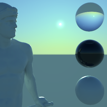
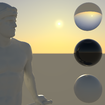
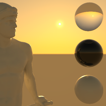
Reduces the intensity of the sun light to a range that can be used without Exposure configuration at your camera.
|
|
|
|
|
| Use Non-Physical Intensity: Enabled | Disabled | Enabled | Disabled |
Use this value to scale the sun disc. The size of the sun in the sky and thus the size of the light source relative to the scene affects the shadow calculation. The smaller the area of the sun, the harder the shadows will be. A large sun leads to a calculation of softer shadows.
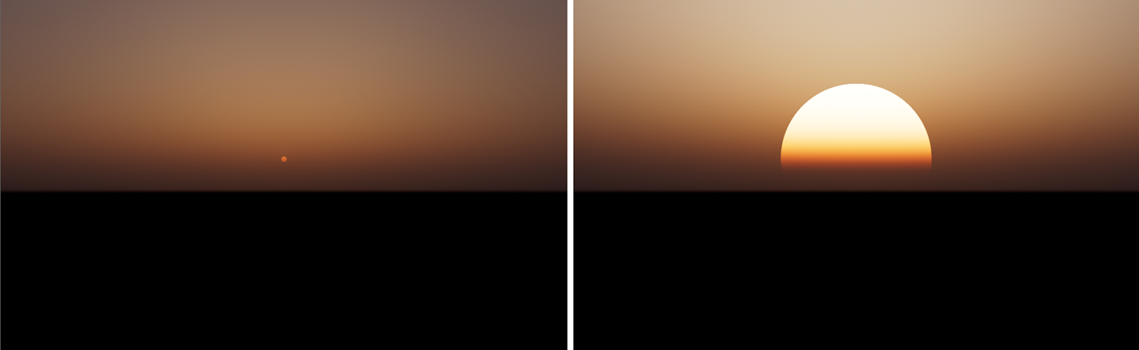 The default Sun Disc Scale on the left, a large Sun Disc Scale on the right.
Here you can choose between two different calculation methods for the color of the sun:
- PRG Clear Sky: This is a modern and precise caclulation model and provides the most realistic results. It is therefore used as the default. With the introduction of this new sky model, the sun radiance is also now calculated from the dataset with known physical sun radiances in the visible light spectrum. The new sun radiance model is able to provide more saturated and strong lighting at sunset and an accurate radiance for direct lighting.
- Legacy: This activates the outdated calculation models to keep older projects compatible.
To take full advantage of the Physical Sun you can combine it with the Physical Sky object. Both objects can be created in one step by creating a RS Sun & Sky Rig from the Environment group.
These settings are specific for Physical Sun lights.
The color of this light source depends on its angle to the XZ ground plane. Lower light angles represent a sun near the horizon and warmer light colors. On the other hand, if the Z-axis of the light source points vertically downwards, this simulates a high noon sun and results in colder light colors. You can further refine this coloring with the following parameters.
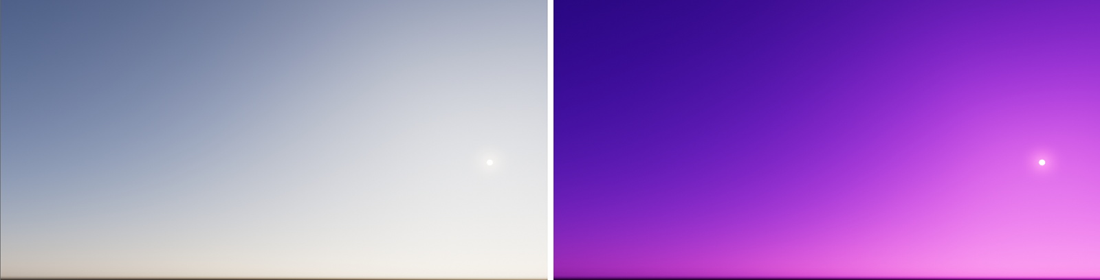
Specifies a hue shift for the color of the sun light. The default value of 0 will yield physically accurate sun light color. Negative values will shift the sun light color towards blue, while positive values will shift it towards red.
|
|
|
|
| Red-Blue Shift: -0.5 | 0.0 | 0.5 |
Specifies the color saturation of the sun light. The default value of 1 will yield physically accurate sun light color. Smaller values will reduce the color saturation of the sun light, with a value of 0 producing pure white light. Values above 1 will exaggerate the color of the sun light.
The sunlight color calculated by the sun position is multiplied by this Tint color. Only when using white the sunlight remains physically correct. Otherwise, the illumination of the sun can be adjusted artistically with this.
 The left image shows the original sunlight, using a white Tint color. On the right, a pink color was used to tint the sunlight.
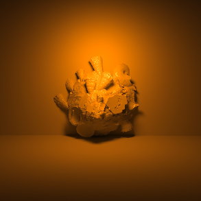
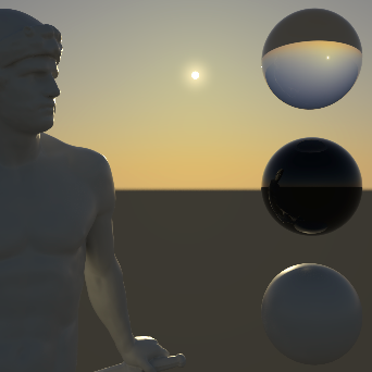
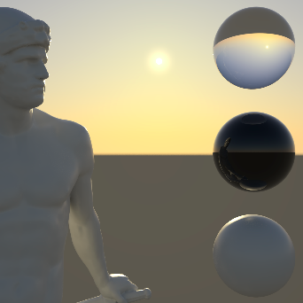
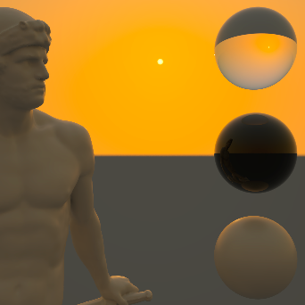
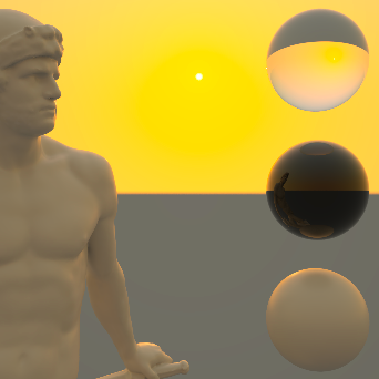
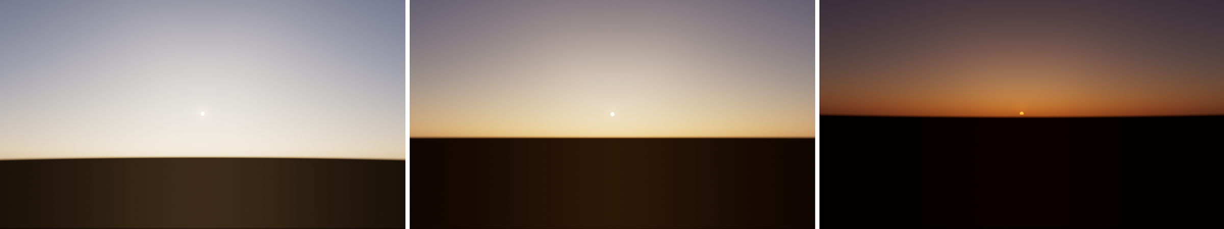
Specifies the haziness of the air – a measure of dust particle pollution. A value of 2.0 represents a very clear, blue sky, while larger values will make the sky a dirty, orange color. The visibility of the sun and sky (if a RS Sky object is used) decreases with increasing turbidity
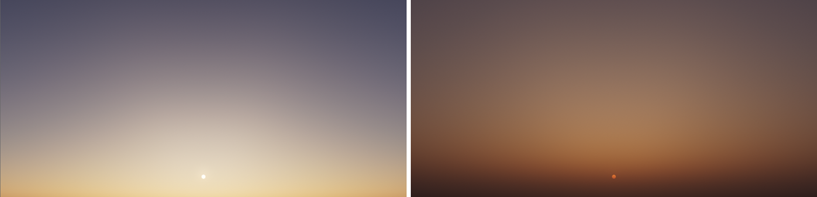 Low Turbidity on the left, high Turbidity on the right..
This parameter is only used with the Legacy Physical Sun calculation mode.
This specifies the amount of Ozone in the atmosphere, with values ranging from 0.0 to 1.0. The default is 0.35, which is commonly used for the Earth's atmosphere. Smaller values will increase the amount of orange in the sunlight, while larger values will make it more blue.
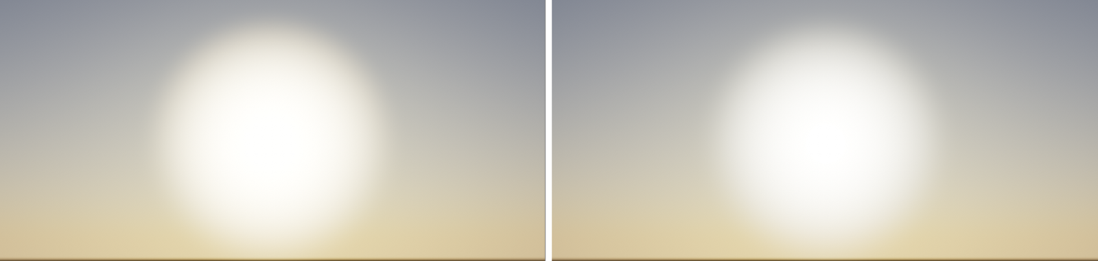 The amount of Ozone also has a subtle effect on the visible sun glow. The left side shows a warmer sun glow with a low Ozone value. On the right, the sun appears slightly colder when a higher Ozone value is used.
Below shows an Ozone demonstration showing lower values resulting in a warmer result on the left to higher values resulting in a cooler result on the right:
|
|
|
|
|
|

Specifies the position of the horizon. Values below 0 will push the horizon down, while values above 0 will raise the horizon. This can be interesting for artistic reasons, as the position of the sun will not be changed, but the resulting colors are still based on the distance between the sun and the horizon.
 This image sequence shows the result of using a Horizon Height of -0.5, 0.0 and 0.5 (from left to right).