Tag Properties
This tab contains all attributes that describe how the collision object interacts with and acts on other simulation objects (e.g., Rigid Bodies or Pyro).
If this option is activated, the object to which the Collision tag is assigned can collide with simulation objects in the scene. Deactivating this option prevents any collisions, regardless of the collision element.
You already know these settings from the Rigid Body feature (Collision Shapes); they work the same way here.
For example, if you have a very high-resolution, complex Collision object, it may make sense to use a simpler collision shape for faster results.
In addition, the collision calculation with rigid bodies may lead to better results when using simpler collision shapes (e.g. cuboids). This can have an effect on rolling balls, for example, which simply roll "rounder".
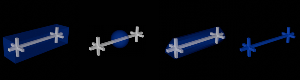 From left to right: Collision Shapes in blue: Box, Sphere, Convex Hulls (geometry accuracy = 0, but can be greatly improved with higher values), Triangle Mesh.
Collision detection calculations are generally computationally intense. However, only they lead to convincing object movements: Bodies can collide with others, come to rest due to friction, etc.
The more complex the body in its shape, the more complex its collision calculation. Therefore, there are some quick-to-calculate substitute shapes in this drop-down menu that can be placed over the actual object. In the simulation, it is often not possible to tell from a distance whether the actual object shape was used for the collision calculation or, for example, only a box that was automatically adjusted to the object size.
The order in terms of computational speed and collision precision is roughly this (from fastest/most imprecise to slowest/most precise): Box, Sphere, Convex Hulls, Triangle Mesh. In detail:
Auto
If Cinema 4D detects that the primitives Cube and Sphere have been used, they will be automatically calculated internally with the options Box and Sphere. Otherwise, Convex Hulls will be used (the default geometry accuracy 5 will be sufficient for most cases and will still check for collision very quickly).
Attention, Auto is only available for Rigid Bodies, not for Collision objects.
Triangle Mesh
The object to which the tag is assigned is defined with its complete shape as the collision shape, which makes this option the slowest, but regarding collision the best, because the exact object shape is used for collision calculation.
However, Convex Hulls with higher Geometry Accuracy can often compute similarly good collisions, but much faster.
Here, one or more enveloping hulls are placed around the object or its parts, which behave similarly to a rubber skin. The Geometry Accuracy parameter is displayed, which defines the number of "rubber skins".
By the way, this equivalent shape creation works exactly as already described for the placement tool at Accuracy.
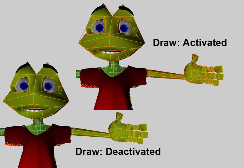
If you want to display the collision shape, activate the Rigid Body Shapes option in the Simulation tab of the Preferences menu. To do this, you must start the simulation, or jump one frame forward from the start frame.
Sphere
A sphere fitted into the object bounding box is used as the collision shape.
Box
The smallest box that includes all object points will be used as the collision shape.
This parameter is displayed if Auto (Rigid Bodies only) or Convex envelope is selected under Collision Shapes (see also Convex Hulls).
With increasing values, the collision shape will approach the actual object shape without reaching it exactly: However, the calculation is much faster than with Triangle Mesh.
If set to 0, recessed indentations or recesses or holes will not be included in the collision calculation, but only a single "rubber skin" will be placed around the object, as shown on the left:

This attribute is also found in the collision partner. Remember that these fields in the two tags are related to each other. For example, a piece of nylon always has the same Bounciness value. If the nylon collides with two objects, one made of fabric, the other made of concrete, the Bounciness value of the nylon remains the same. However, the two other objects have completely different Bounciness values. The nylon is hardly or not at all cushioned by the concrete, but the fabric allows the nylon to cushion relatively strongly.
This attribute is also found in the collision partner. Remember that these parameters in the two tags are related to each other. For example, the surface that a cloth object collides with can have different Friction values. For example, a piece of nylon always has the same Friction value. If the nylon collides with two objects, one of which is a rock and the other a block of ice, the Friction value of the nylon remains the same. However, the other two objects have completely different Friction values. The block of ice causes almost no friction, while the rock generates relatively high friction when it collides with the nylon.
This attribute can also be found in the collision partner. Remember that these parameters in the two tags are related to each other. For example, if one of the two settings has the value 0, the overall Stickiness is also 0.
Here you can set the polygon side from which collisions are to be checked. Physically correct would be Both. However, more complex collisions can lead to penetrations that can no longer be eliminated by this setting. Imagine, for example, a T-shirt in the armpit area of a running character: it can happen that parts of the T-shirt are pressed into the character geometry. If you now set the Front here, it is possible for the fabric to move out of the character again, since the collision from behind is deactivated. In addition, a small impulse is even created from the surface to better eliminate any collision penetrations.
Back, for example, would make sense if you enclose a sphere in a larger sphere.
The polygon normals are decisive for the direction: Front is where the polygon normal points.
Liquid collision
In the following example, you can see liquid particles in a cylinder: on the left in Surface and on the right in Volume Mode. The latter is literally watertight, while some liquid particles "break out" on the left.
Collision objects can collide with a number of elements: e.g. rigid bodies, soft bodies, particles, etc. Depending on the element type, the collision can be calculated in different ways. In combination with the fluid simulation, you have 3 modes:
- Surface: A corresponding surface is assumed through which the liquid particles should not penetrate. Please note that the Collision Shape and Collision Side parameters described above are evaluated! Please note that this mode is not as precise as the Volume described below and that penetration can occur - especially with fast particles/collision objects. Surface generally works well if the liquid particles only collide ("bounce off") briefly and then move away from the surface. If the liquid is to remain in permanent contact with the collision object, the following Volume mode is more suitable.
Surface is faster in most cases than Volume in the calculation (exception: basic objects cube or sphere).
Please note that the Collision Side parameter located in front of it must be set accordingly! - Volume: in this mode, a trick is used: instead of checking particles for collision with a surface, the collision geometry is replaced by a volumetric shape formed by voxels and used for collision detection (for more details, see Voxelization). Volume calculates more precisely - but more slowly - than Surface and is able to simulate “watertight” collision objects in the truest sense of the word. Use this mode if you want to simulate liquids in containers: e.g. red wine in a glass, sloshing water in a canister, etc. This option works best with objects that have a volume. Here it is clear where the inside and outside are. However, non-voluminous objects (e.g. a pane) can also be made voluminous in terms of collision: with the setting On Open Geometry, these are converted internally into a voluminous collision shape.
- Off: This switches the mode off. There is no collision detection with liquids, but there still can be with other elements (e.g. rigid bodies) depending on the settings.
Volumes need enough volume to work well. Thin collision walls don't work so well, they quickly become penetrated. Note that the use of invisible (= not rendered), thick-walled collision replacement objects is often a good tool.
Here you specify the side from which liquid particles can collide with the volume. You have the following selection options:
- Outside: A collision occurs when particles hit the collision surface from the outside. This is the normal case.
- Inside: Collision takes place when particles hit the collision surface from the inside (e.g. a glass sphere filled with water).
- Both: Collisions take place both on impact from the outside and from the inside. However, this mode is less robust than the other two, which can result in penetrations!
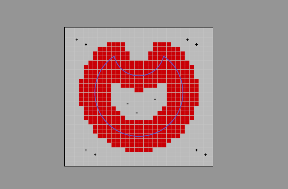 A cross-section through a collision surface (blue) in Outside mode (in Inside Mode, the plus and minus signs would be reversed).
Here are some details about the Volume mode, which will help you to better understand the next parameters described. You can see the collision surface of an object in blue in the illustration. The black, square border is a collision bounding box. This is not identical to the familiar object bounding box, but slightly larger. Several layers of voxels (red) are created around the collision surface on the inside and outside (general details about voxels can be found here). The distance to the nearest collision surface is stored in each red voxel.
Outside the red voxel layers, there are also voxels inside the collision bounding box, but they only have the "Inside" (+) and "Outside" (-) properties saved. The area of the + sign indicates the space in which liquid particles can move.
As soon as liquid particles enter the collision bounding box, collisions can be detected very precisely.
The above description applies to all mesh objects except the basic objects Cube and Sphere, which work without voxels. Their volume representation is mathematically defined, which is more precise, faster and requires less memory. So by using these two object types you could save resources.
In the Voxelization parameter, select how the voxel size is to be determined:
- Relative: a percentage of the longest object bounding box side is used here.
- Absolute: this allows the voxel size to be entered in absolute centimeters.
Depending on what you have defined for Voxelization, enter the voxel size here as a percentage of the largest bounding box length or absolutely in centimetres.
The smaller the voxel size, the better the collision mesh can be simulated, but the more complex the calculation is and vice versa. Voxels that are too large lead to leaks, i.e. penetrations.
Generally speaking, the voxel size should be about the same size as the liquid particle size, but can also be slightly smaller. The default liquid particle size is 6 cm, so a voxel size of about 3-6 cm would be appropriate. However, you can of course go further down to better simulate the collision mesh. It may then be necessary to increase the voxel areas (see next parameter).
Interior Voxel Range[0..2147483647]
Exterior Voxel Range[0..2147483647]
Starting from the collision mesh, a defined number of voxel layers are created on the inside (Interior Voxel Range) and the outside (Exterior Voxel Range). These are the red voxels in the figure above.
If you choose very small voxel sizes (see previous paragraph), collision problems may occur. The reason: the liquid particles are detected too late, then overlap, and bouncing behavior may occur, for example. In such cases, it can help to enlarge the voxel areas on the collision side.
Very fast liquid particles also benefit from larger voxel areas!
Other things to know about liquid collision
- It can happen that different collision methods "wrestle" with each other: imagine a rigid body floating on a liquid that is pressed against a collision object by the liquid; who wins? This could lead to penetration. You can influence this with the parameter Collision Priority ).
- The following applies to the Volume Mode: If you create liquid particles in a negative space, they will be drawn into the positive space within the collision bounding box with great force.
- The creation of voxels around mesh surfaces is also used with the Volume Builder (Volume Type Signed Distance Field (SDF)).
Preprocess
If you have defined Triangle Mesh under Collision shape, you can have the geometry pre-processed internally here by giving it volume. This benefits the volume collision mode the most, which is effectively supported by the Wall thickness mode. Volumes with a clearly defined inside and outside are then created.
You can select from the following options:
-
Off: No preprocessing takes place here. The geometry is used for collision as it is. This can quickly lead to problems (= intersections) in fluid collisions with objects that do not include a volume (e.g. a disc)!
There are some exceptions here, such as the primitive object Plane, which is processed internally as a cube with regard to collision. If you make this editable, however, these special rules are switched off - but only incidentally. -
Thickness:
You can use this to create a volume from any object that is made up of just one polygon layer. Internally, this works in the same way as the Thicken generator. You define the wall thickness using the Thickness parameter described below.
In the video above, you can see a red, fast-moving collision object colliding with liquid particles. On the left, On Open Geometry is set to Off, on the right to Wall thickness. On the right, the collision works perfectly, while on the left there are massive penetrations.
-
Close Holes: This is used to close holes in the mesh. Definition: Holes are where there are open edges: polygons that have no connection on one side. This includes, for example, a hemisphere made of a single-walled polygon mesh, but not a hemisphere whose walls have a thickness of 1 cm, for example.
Here you define how thick the generated wall thickness should be. The thicker this is defined, the more accurate and reliable the collision calculation will be.
However, the higher you set the Thickness, the more visible the distance between the collision partners becomes, which is why you can use Position to move the wall thickness inwards (negative values) and outwards (positive values) until it fits visually.
To do this, load the scene above and vary Position. Switch to the "Position" camera. The effect of this parameter can then be observed very clearly in image 5.
Exclude polygons
This command excludes all selected polygons from the collision calculation.
Hereby all excluded polygons are considered again for the calculation.
Once you have made a different polygon selection, you can use this command to quickly display the excluded polygons again, overwriting the current polygon selection.
If this option is activated, all excluded polygons are displayed with red edges in the editor. Internally, the collision object is always divided into triangles so that the excluded polygons are displayed triangulated. Deactivating this option hides the polygons in the editor again.