On this page you will learn more about the basic settings of the Pyro Emitter tag, which is responsible for creating the gas to be simulated in the area of an object. The following topics will be covered:
Simulations can be very computationally intensive and therefore benefit from the most powerful hardware possible to provide meaningful rendering already in the viewport. As with rendering with Redshift, graphics cards can generally offer much better performance values compared to using the CPU. It is therefore advantageous to always activate the most powerful component of your computer for the simulation as well. To do this, open the Pyro Scene settings, which are linked via the Pyro Output object. You will find a Scene tab there, where you can first select between CPU and GPU under Device. If you have several GPUs available, you can then also directly select the desired device to be used for the simulation calculation. Here it generally makes sense to select the most powerful graphics card, or in the case of a Pyro simulation, the GPU that has the most memory.
Adjust the Voxel Sizes
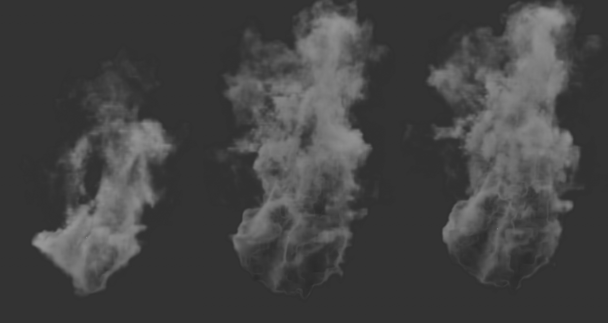
There are now two initial, important settings that you should adjust. In the Pyro Scene settings of the Pyro Output object you will find the Voxel Size setting. This defines how finely the simulation will subdivide the space. Therefore, a small Voxel Size automatically leads to a more accurate calculation and a more detailed simulation. At the same time, however, the computing and memory requirements of the simulation increase accordingly. It is therefore necessary to adjust this value to the expected size of the simulation. At the beginning, the size of the object to which you have assigned the Pyro Emitter tag can serve as a reference value. It therefore makes sense in any case to also pay attention to realistic sizes in the Pyro Scene settings on the Pyro Output object. The following figure shows the influence of the Voxel Size on the simulation result.
In this example, a deformed ring is used as a Pyro Emitter. The upper images show the simulation result after 40 animation frames. Below is a close-up of the ring used as a pyro-Emitter, so that the distribution of the newly formed gases in the volume of the object can be surveyed. The Ring object itself has been hidden for this.
In the image above, from left to right, Voxel Sizes of 5cm, 1cm, and 0.1cm were used. The width of the deformed ring, which serves here as a Pyro Emitter, is about 20 cm. It can be clearly seen how reducing the Voxel Size leads to more effective filling of the ring with gas and to a more detailed simulation. At the same time, however, the simulation time increases considerably and the memory requirement also skyrockets.
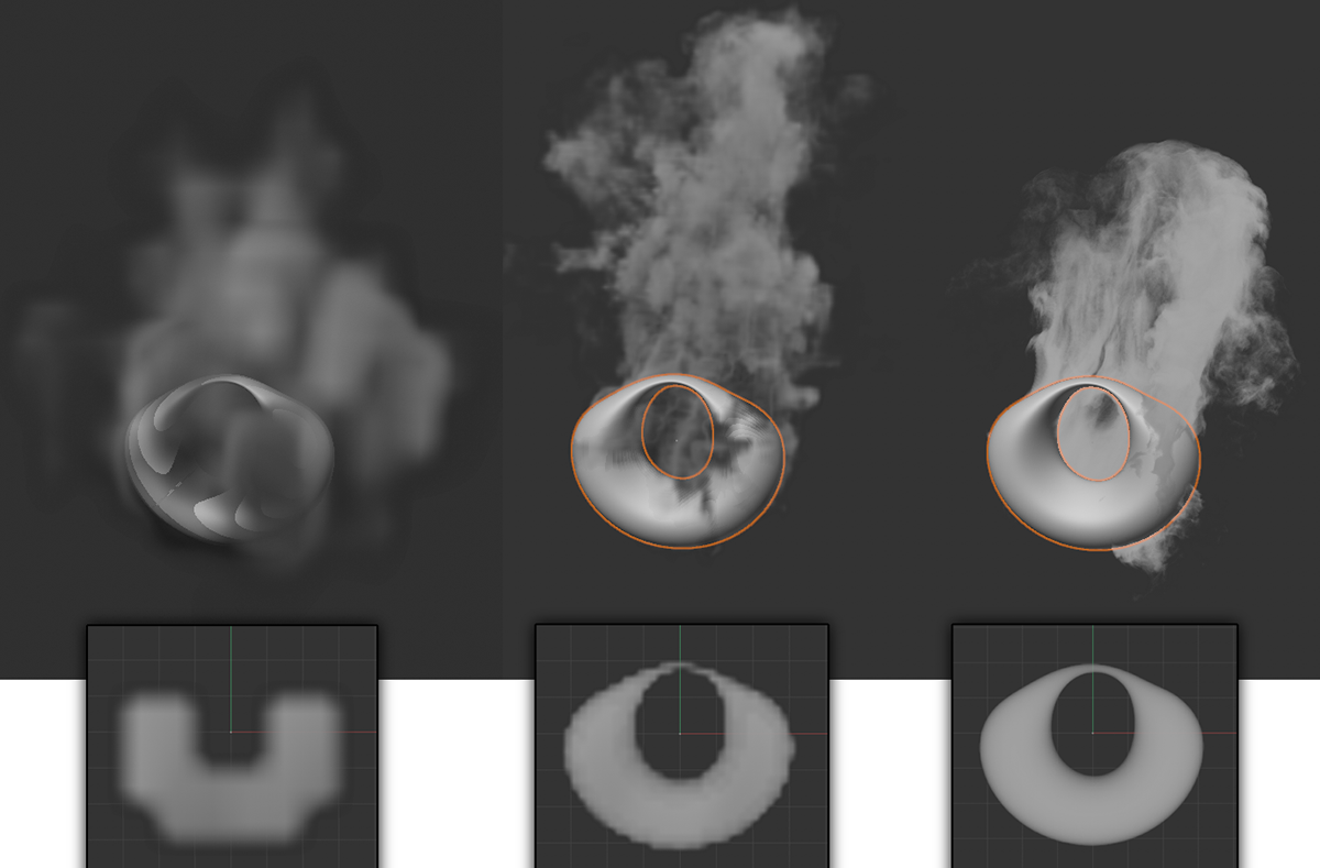
Especially with larger objects, a small Voxel Size can quickly lead to insufficient memory being available. In such cases, one of the things that can help is to adjust the Voxel Size for sampling the volume at the Emitter object. This is possible by using the Object Fidelity on the Pyro Emitter tag or Pyro Fuel tag. This percentage value refers directly to the previously set Voxel Size. Thus, with Object Fidelity values below 100%, you can selectively reduce the number of voxels in the area of the Pyro Emitter. This results in smoothing and coarsening of the detected Emitter shape and neglect of sections of the object whose cross-section is smaller than the Voxel Size multiplied by the Object Fidelity. Often, however, this inaccuracy can be neglected, especially if we can save some memory and computing time. The following image also shows an example of this.
This image sequence again uses the deformed ring from the last example as the Emitter. A Voxel Size of 1cm was used for all three images. The only difference between the images is the Object Fidelity setting. 10% was used on the left, 50% in the middle and 100% on the right.
As can be seen in the figure above, a strong reduction of the Object Fidelity may lead to the fact that the entire object is no longer used as a Pyro Emitter. Accordingly, less smoke, hot gas or fuel are simulated there. Likewise, the distribution of the generated gas can become more uneven, as only the more voluminous sections of the object are filled with gas. However, the figure also makes it clear in this example that the differences can be quite small in some cases. Thus, the difference between the middle and right simulation result turns out to be quite small. However, we save many Voxels in the volume.
So, to summarize, use the Voxel Size from the Pyro Scene settings of the Pyro Output object to control the scale of the simulation and thus its level of detail. It also provides you with a tool for optimizing the memory requirements and the calculation times. Smaller Voxel Sizes always mean more complex simulation calculations and increased memory requirements. This is capped for simulations. If, for example, too many Voxels have to be generated due to a large explosion or a too small Voxel Size setting, it may no longer be possible to capture the entire volume of the cloud, flame or explosion. There may then be missing areas in these sections, e.g., in a cloud.
You can find examples and solutions to avoid this problem in the description of Pyro simulation settings. Therefore, always keep the Voxel Size as large as possible and as small as necessary.
Customize the level of detail
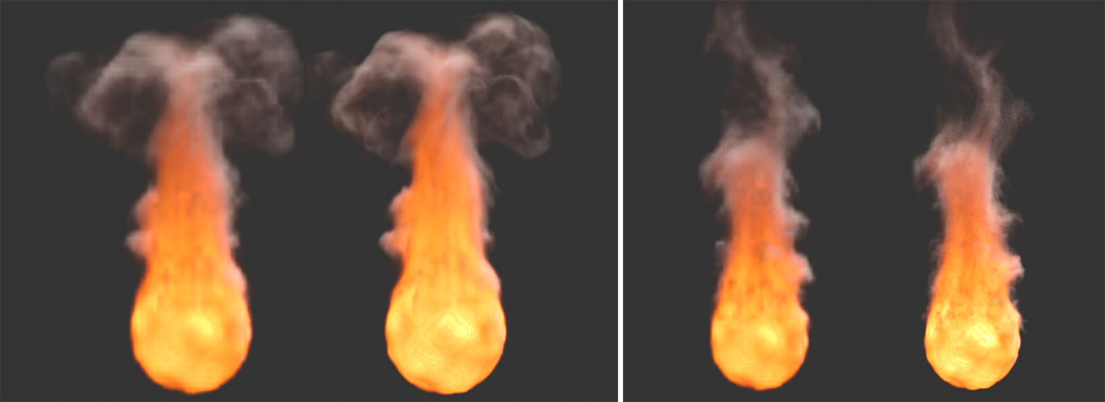
An additional option is the subsequent upscaling of the voxel set to add additional details to a lower resolution simulation without having to change the basic shape of the simulation. Normally, it is the case that the course of a simulation changes when smaller voxels are used. This makes it difficult to use a quick simulation with large voxels and then simply downscale the voxels for rendering. However, by using the so-called Upres function, the existing simulation data can also be used, subsequently subdivided and detailed by superimposing a noise structure.
Here are examples of the Upres effect. The left flames in both examples were simulated with low voxel density. To the right of each is the version simulated by Upres. There, more details are visible and the result appears sharpened.
To do this, first have the simulation saved with a larger voxel size as a cache. Then use the Upres options within the Cache section of the Pyro Output object. There, an additional voxel subdivision ( Upres Factor parameter) and additional noise overlays can be defined. If a new cache is then calculated, it uses the low-resolution caches as a basis and adds the new details there (see also the examples in the figure above). Since this recalculation is done image by image, the basic shape of the rough simulation is preserved. In addition, this makes it quite easy to create different levels of detail of a simulation.
Note:
When calculating the Upres effect, the Velocity component of the simulation (velocity) is mandatory. This must therefore be a component of the lower resolution cache that serves as the basis for refinement.
Use Vertex Maps
In the above example, a complete object was used as an Emitter. However, you can also define only parts of a surface as Emitters. This then also makes it possible, for example, for fire to spread slowly over an area or for smoke to linger only in certain places.
The solution to this task lies, for example, in the use of Vertex Maps. These can be created very quickly by converting a point selection if you call the Set Vertex Weight... command in the Select menu and then define a value of 100% in its dialog, for example. However, a Vertex Map can also be created directly by painting, which then also allows variable intermediate values and interpolations between neighboring vertex map values to be realized.
To do this, select your polygon object (a parametric object must first be converted using Make Editable) and then select the Vertex Map tag in the Other Tags category of the Object Manager 'sTags menu. Creating this tag automatically activates the Paint Tool, which you can otherwise also access from the Tools menu. The intensity can be adjusted on the tag via the Opacity setting. Otherwise, you can read details about this Paint Tool and the Vertex Map tag itself here.
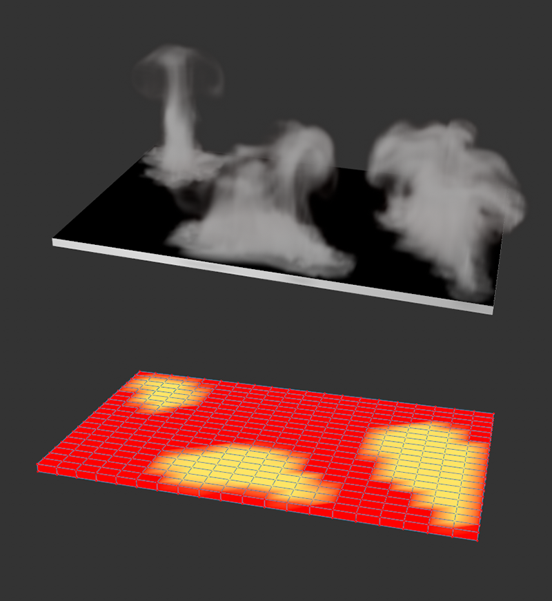
Below is a flat cuboid on which a Vertex Map has been defined. Above you can see the result of a smoke simulation for this object.
Wherever the value 100% is stored in the Vertex Map, the full effect of the Pyro Emitter can take effect. Areas with lower weighting in the Vertex Map, for example, will then generate correspondingly less gas. Wherever the Vertex Map contains 0%, no more Pyro property generation takes place at all. For this to actually work, you still need to assign the created Vertex Map correctly in the Pyro Emitter Tag. For example, in the image above, the Temperature and Fuel options have been turned off in the tag so that only Density is generated (for simulating smoke, haze, fog, etc.). In the Density section of the settings you will then also find the option to assign the Vertex Map as a Density Map by dragging and dropping directly from the Object Manager. As can be seen in the upper half of the figure, smoke generation now occurs only in those areas of the object that contain Vertex Map values above 0%.
The same principle works in this way for the generation of Temperature and Fuel in the Pyro Emitter tag. Since an object can have multiple Vertex Maps, using individual Vertex Maps to control all these Pyro Emitter properties is also not a problem. The Pyro Emitter tag also provides a field for assigning an Emission.Map. Here, in addition to Vertex Maps, Vertex Color tags and Polygon Selection tags can be assigned, through which the entire Pyro emission of the object is then controlled. In the case of an assigned Vertex Map, Density, Temperature and Fuel can then only occur at the object where Vertex Map values are above 0%.
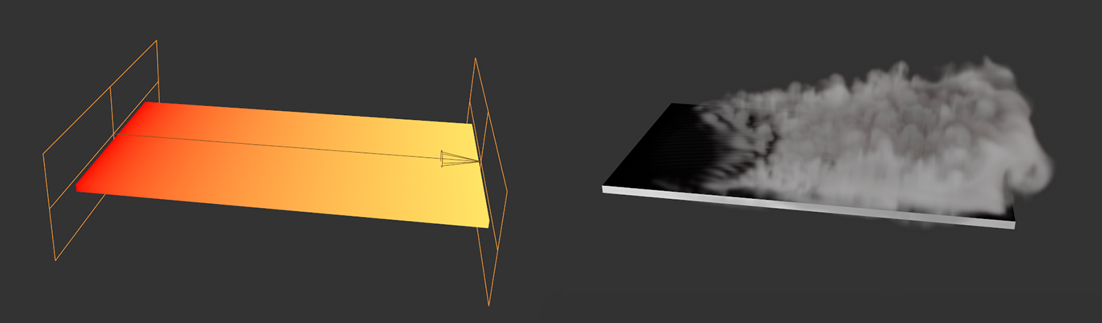
The use of Fields within a Vertex Map opens up further options.
In addition, you will find an option in each Vertex Map tag and Vertex Color tags to use Field objects as well. For example, in the image above, a Linear Field was used to produce a perfect weighting curve along the width of the flat box. Accordingly, the simulation results in a perfect transition in the intensity of the simulated smoke. The only prerequisite for this is that the point density of the object is as uniform and fine as possible in order to be able to reproduce all variations in the Vertex Map or Field strength.
Note 1:By the way, using fields when creating Vertex Maps tags or Vertex Colors tags is also possible with parametric objects. This means that basic polygon objects do not necessarily have to be converted to polygon objects first.
Note 2:When using soft weighting transitions, Voxel Size and Object Fidelity again play a role. Fine nuances in the Vertex Map can only be detected and implemented by the Emitter if appropriately sized voxels are used.
Example use of a Vertex Color tag for the color in the Pyro Emitter tag. Combined with the Vertex Map described above for the linear progression of the fog emission along the cube. The following section gives more information about vertex colors.
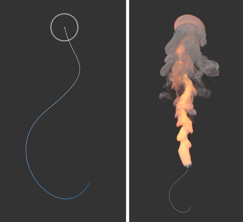
By the way, Vertex Maps and Vertex Color Maps can also be used with splines if you want to vary the properties of the Emitter along the spline. Just remember then also that on the Pyro Emitter tag it is essential to activate the option for Surface so that there is a tube-like volume around the spline that the Emitter can use. You will learn more about this in the following section.
On the left, you can see a close-up of the spline used as the Emitter. The circle at the top marks the spline point that was weighted with 100% in the Vertex Map. To the left is the result of the simulation, which generates smoke and heat only at the top of the spline after the Vertex Map has been assigned appropriately in the Pyro Emitter tag for the Density and Temperature properties.
Use Vertex Color tags
Similar to the Vertex Map described above, an object can also have multiple Vertex Color tags that can also be added to the Emitter object as tags in the Object Manager. This type of tag can also be found in the Tags menu of the Object Manager under Other tags and allows you to assign RGB color values and alpha values to each point of a geometry.
Colors and alpha values can be applied individually with the Paint Tool, which can be found in the Tools menu. For this purpose, you can select directly at the Paint Tool via its Paint Mode whether only RGB values (colors), only alpha values or both should be painted at the same time. In addition, it is also possible to use Field objects directly in the Vertex Color Tag to create accurate gradients or random animated alpha values, for example. For complex color gradients or fine structures, there should be enough points on the object, distributed as evenly as possible. Color and alpha values can only be painted and saved on the object where points are present. The colors between the points are created by simple interpolation. This is the principle that the Vertex Color tag has in common with the Vertex Map tag.
If a Vertex Color tag is present on the object assigned with a Pyro Emitter tag, it can be evaluated for Density, Temperature or Fuel generation and also assigned for density coloring and transparency as a Color Map. In addition, this entire emission at the object can also be controlled by assigning it as an Emission Map. The following figure gives an example of using a Vertex Color Map.
On the left you can see the Fields list of the Vertex Color tag. There, a linear field in gradient color mode was used to mix different colors evenly. In addition, the alpha values there were set so that the opacity of the colors drops in the middle of the gradient. On the right is the result after assigning the Vertex Color tag as a Color Map in the Pyro Emitter tag. Only the simulations for Density and Color were activated.
Using the Vertex Color tag as a Color Map in the Pyro Emitter tag.
Note:When using Vertex Color tags for the Density Map, the Temperature Map or the Fuel Map, please note that the brightnesses of the vertex colors and their alpha values are multiplied together and thus always evaluated together.
Vertex colors can also be used for the points on splines and have the advantage that the color values are automatically interpolated between neighboring spline points. You can find an example of this in the figure below. There, on a converted N-Side spline, the six vertices were individually colored by the paint function of the Vertex Color tag. If a Pyro Emitter tag is then assigned to the spline and the Surface mode is used there, Density can be generated in the area of the spline. If we then assign the vertex colors as a Color mMp, appropriately colored smoke is automatically created. Note that to render these colors, the On Export setting must be enabled for the colors on the Pyro Output object!
Using the Vertex Color tag as a color map for a spline object.
Constrain the Emitter via a polygon selection
As introduced in the previous two sections, vertex maps and vertex colors can be used to control individual properties. Since these properties can be assigned soft transitions or even color values, this results in additional variation possibilities for the Emitter. In some cases, however, it may be desirable to limit the emission to a polygon selection. Polygon Selection tags for the properties Density, Temperature and Fuel can be used for this purpose. In addition, there is also an Emission Map property that can handle polygon selections in addition to Vertex Maps and Vertex Color Maps, and thus can be used to absolutely constrain all Pyro Emitter properties. This means that not all used properties have to be assigned to the same vertex map, for example, in order to limit the emission, but these properties can still be used separately.
Using the Surface Emitter
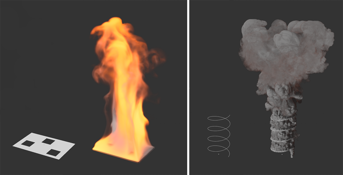
As mentioned earlier, Emitter objects must actually be closed volumes for the Pyro Emitter tag to work reliably. However, for very thin objects (thinner than the Voxel Size of the Pyro Scene settings in the Pyro Output object), when holes are present, for one-sided objects, and also for splines, the Surface option on the Pyro Emitter tagcan also be used. This allows a distance to be defined around the spline or around the polygons, which then allows the Emitter to generate gas there again. This option is already active by default, so that any spline or polygon object can first be used directly as a Pyro Emitter. So if you assign a Pyro Emitter tag to a closed volume object, such as, for example, a sphere or a cube, you can also switch this option on the tag to Volume to restrict the creation of the gas to the entire interior of this object.
Here you can see two examples of how to use the Surface option. On the left a simple Plane is burning, from which some polygons have also been deleted. On the right, a Helix spline generates steam.
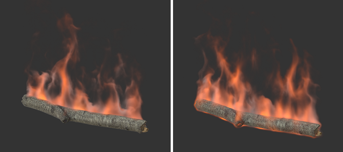
However, in addition to the above examples, this option can also be used for closed objects, for example, if you want to increase the volume of the Emitter beyond the boundaries of the assigned object. Here, too, is an example:
Here, a branch object (found in the Asset Browser) has been defined with the Pyro Emitter tag as the Emitter. On the right, the Surface mode has been activated instead of the Volume mode. The flames are now also flickering over the surface of the piece of wood.
As the figure above shows, scaling the Emitter up with the Surface option can also help to make the simulation visible outside an object. In the specific case of the burning branch, this means that the flames also seem to bend around the branch and not just coming out of the top.
Using the Points mode
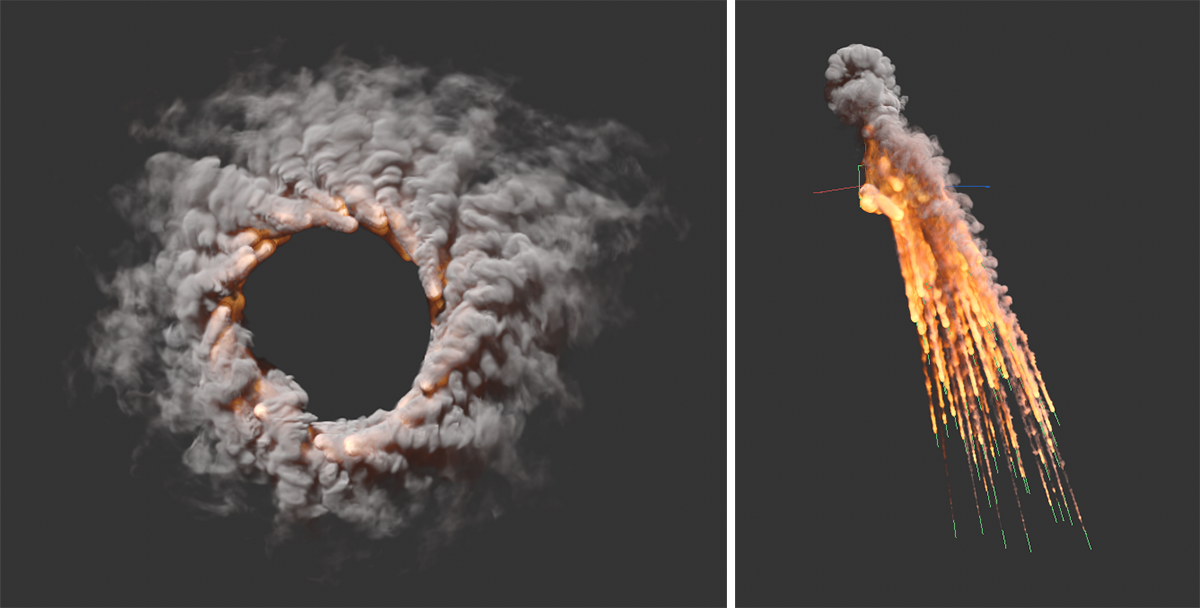
Particles and the matrices of a MoGraph Matrix object can also be used as Pyro Emitters. In these cases, activate the Pyro Emitter tag 's Points mode. Again, the surface Thickness value can be used to define a spherical volume around the particles or matrices in which the selected Pyro components are then to be generated. In principle, this mode can also be used with splines or polygon objects. In that case, only the points of these objects are used and converted to spherical volumes accordingly. The following figures represent examples of this.
On the left, particles were forced into a circular path by a rotational force object, emitting Density and Temperature. On the right, simple particles exit an Emitter and are pulled down by gravity. Since a End Scale of 0 was used for the particles at the Emitter, the fire paths automatically thin out at the bottom of the image.
When using Thinking Particles, the TP Geometry object must be assigned the Pyro Emitter tag. P Set Data Nodes can be used not only to assign individual sizes or colors, but also to assign values to specially created variables, which can then be evaluated by the Pyro simulation. If you create float variables named density, temperature or fuel in the TP Settings, you can assign these values individually for all particles. An example of this can be seen in the following video clip.
In the example video above, the particles shown in red were emitted first. These have been given temperature values, via the assignment of a temperature variable, that are slightly above the ignition temperature of the fuel that is subsequently generated by a second Emitter. These fuel particles (by assigning a fuel variable) are shot at the heated particles and thus ignite when they hit each other. Pressure, temperature and density are created there. The effect is similar to the muzzle flash of a cannon, for example.
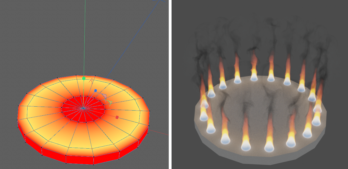
The following example also uses the Points mode, but this time with a polygon object. To ensure that there are only small flames at some points on the surface, a vertex map is created where all points that are to belong to the Emitter are given a weight of 100%. This vertex map is then assigned as the Emission Map.
Here you can see an example where the Points mode is applied to a polygon object. On a flat cylinder, 100% weights were stored for a loop of points on the upper cap and used as an Emission Map.
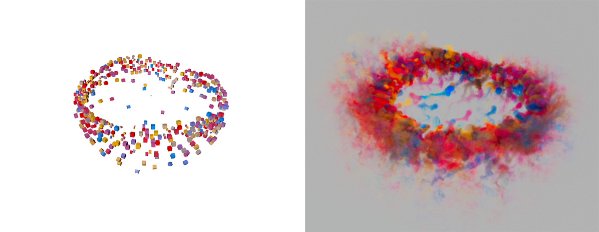
Finally, the Points mode can also be combined with the MoGraph Matrix object. The color of the matrices can also be transferred to the simulation. The following image shows an example of this.
Here, matrices were randomly colored and moved. This creates a waving cloud of color, as seen on the right.
 In this example, a deformed ring is used as a Pyro Emitter. The upper images show the simulation result after 40 animation frames. Below is a close-up of the ring used as a pyro-Emitter, so that the distribution of the newly formed gases in the volume of the object can be surveyed. The Ring object itself has been hidden for this.