Optimal mapping
These functions attempt to apply an optimized UV mapping based on the object to prevent parts of the UV mesh from overlapping, which is quickly the case with more complicated objects. In addition, depending on the parameters set, groups of UV polygons are arranged at a fixed distance from each other and with maximum utilization of the texture area.
There are 3 different algorithms:
- Packed: an automatic process that unwinds, relaxes and optimally arranges ("packs") your UV mesh. This is the most modern and therefore recommended solution (see also Packed below).
- Cube: Divide the UV mesh groups according to the area size (see Cube below).
- Angle: Divides the UV mesh groups taking into account the surface normals.
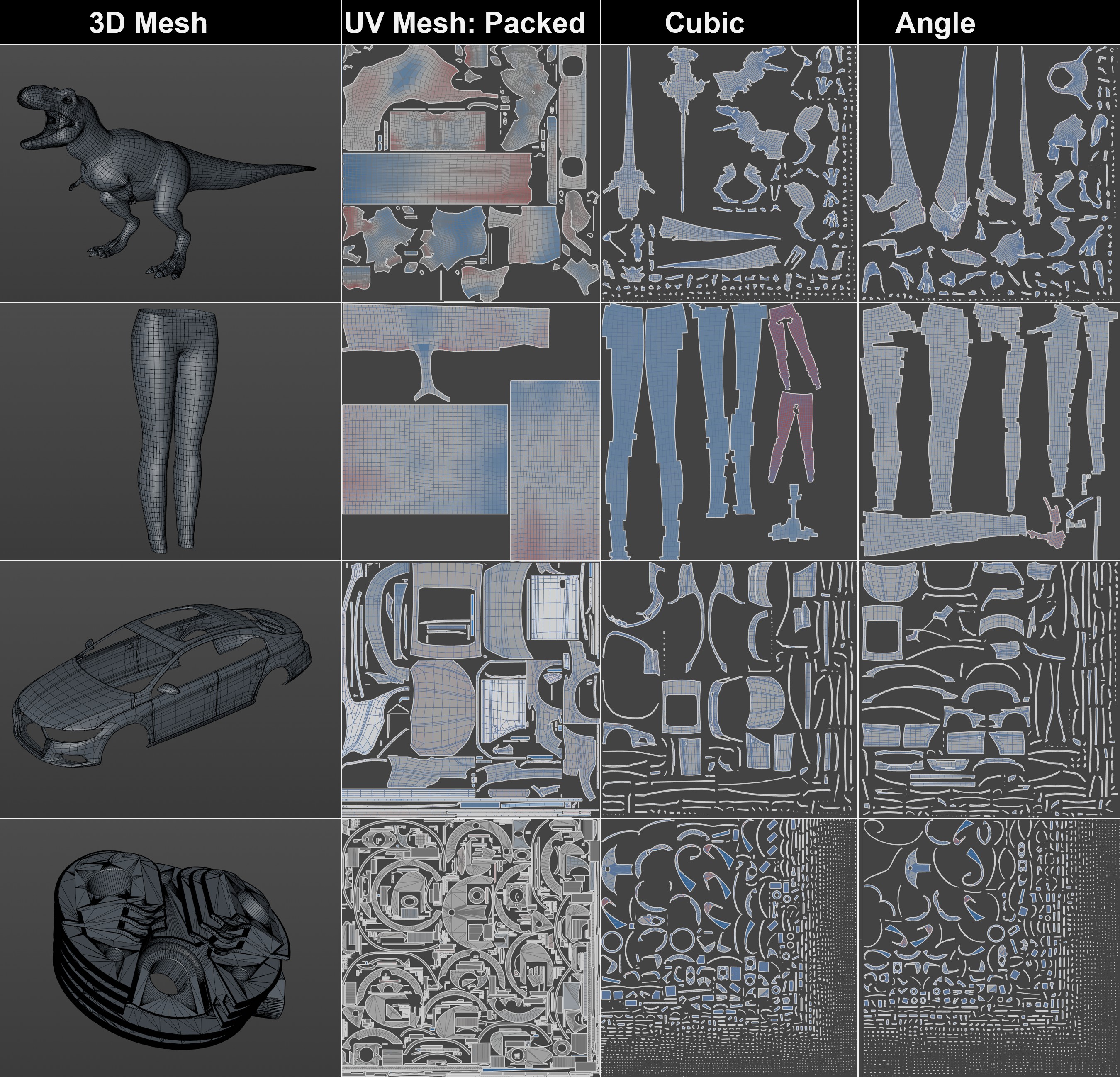 The various automatic methods of unwinding a UV mesh. As you can easily see, packed leads to the best results. Note in particular how densely the UV islands can be packed, making optimum use of the texture space.
Packed
This algorithm does many things at once: it splits the UV mesh into as few UV islands as possible, which are as undistorted as possible and whose scaling matches the 3D geometry as closely as possible. The algorithm is able, for example, to recognize cylindrical sections or cones and unwind them accordingly. Strip-shaped contours are also recognized and sensibly unwound. Many such useful functionalities are built in and work without further intervention.
The UV islands are then packed, i.e. arranged as densely as possible in the UV working area without overlapping, making optimum use of the surface area.
This automatic method is the all-round carefree solution if, for example, you need to quickly:
- want to paint an object using projection painting in the 3D view
- Materials (including multiple materials and using shaders) on an object using object baking.
You will receive a fully functional UV mesh for this, which you can use to carry out the above tasks without any problems.
However, if you want to have full control over the unwinding process, you need to do a lot more manual work (e.g. UV unwrapping). With the necessary know-how, you can then design your UV mesh as you wish.
You can find this new algorithm here in the "Optimal Mapping" tab of the UV Manager and everywhere where UV meshes can be processed, e.g. in the Create UVW from Projection command (here a usable UV mesh can be created from an object without any UV coordinates with 2.3 clicks), in the Paint Assistant, etc. These generally produce the same result, only minor differences are possible in the distances between the UV islands.
Cube
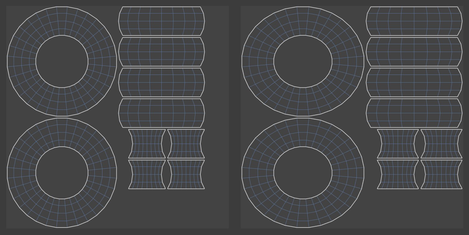
Cube internally places a cube around the object, which is used (and Area Factor) to decide how the UV polygons are divided. As you can see from the figures below, a ring has been viewed from 6 sides. Since a ring, viewed from the side, has 2 sides (outside and inside), 8 UV polygon groups are formed from the 4 sides of the internal cube. The two ring groups represent the UV polygons of the top and bottom of the ring.
Settings
Resolution
Enter the planned size of the texture in pixels here. This is only used to determine the gap size in pixels defined under Spacing (Px).
Spacing (px)
Under Spacing (px), specify the distance between the separate polygon groups. Enter small values here too, as otherwise the UV polygons will have to be reduced in size to fit on the surface of the texture.
Allow Stretch
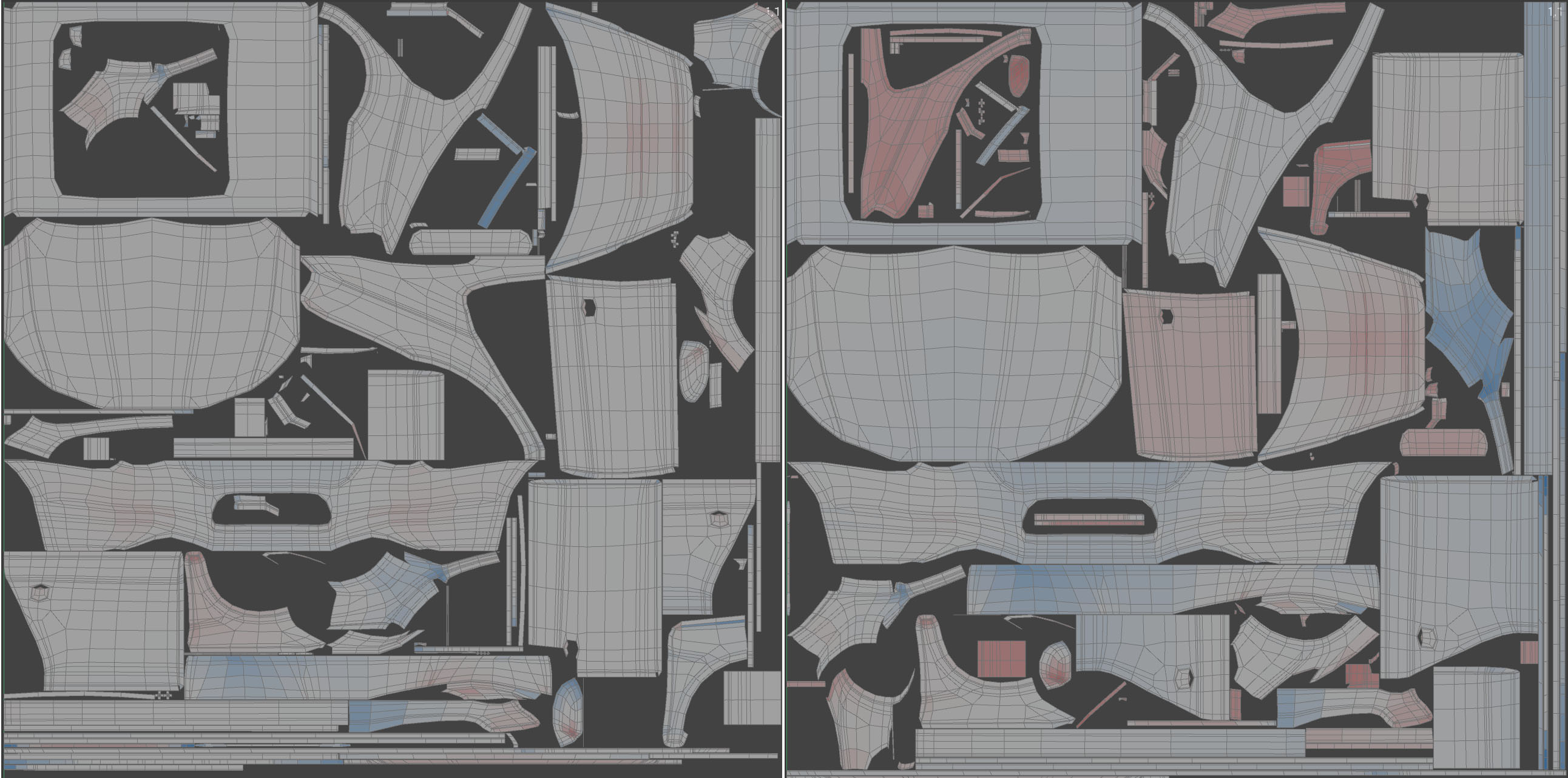 Allow small value for stretching on the left, large value on the right. The UV mesh occupies 10 percentage points more texture area on the right.
With this parameter, you can use larger values to determine whether UV coordinates can make even better use of the texture space by stretching them accordingly. As you can see in the above illustration on the right, the - undesirable - distortion (more "red" in the view) increases.
Area Factor
This factor (only if 2D is deactivated) defines threshold values for the algorithm from which UV polygons are added to existing groups, although they should not belong to them according to the definition (cube mentioned above).
If you want to know exactly: The area factor is the percentage value up to which the area size of the corresponding polygons may fall below the average area size.
Relaxation Steps
Here you combine parts of the UV relax algorithm with the optimum mapping. Values of 1, 2 etc. apply this algorithm correspondingly often. 0 dispenses with the combination.
Maximum Distortion
In the Maximum Distortion input field, you can specify the deviation of the angles of the surface normals of connected polygons from which polygon groups are defined. It is important to enter smaller values here, as otherwise little changes compared to the original UV mapping. The smaller values you enter, the more polygon groups are formed. This goes so far that at the value -1, no more polygon groups are formed, but each UV polygon is spatially separated from its neighbouring polygon. 100% corresponds to a 90° difference, 50% to 45° and so on.
Overlay Identical eometry
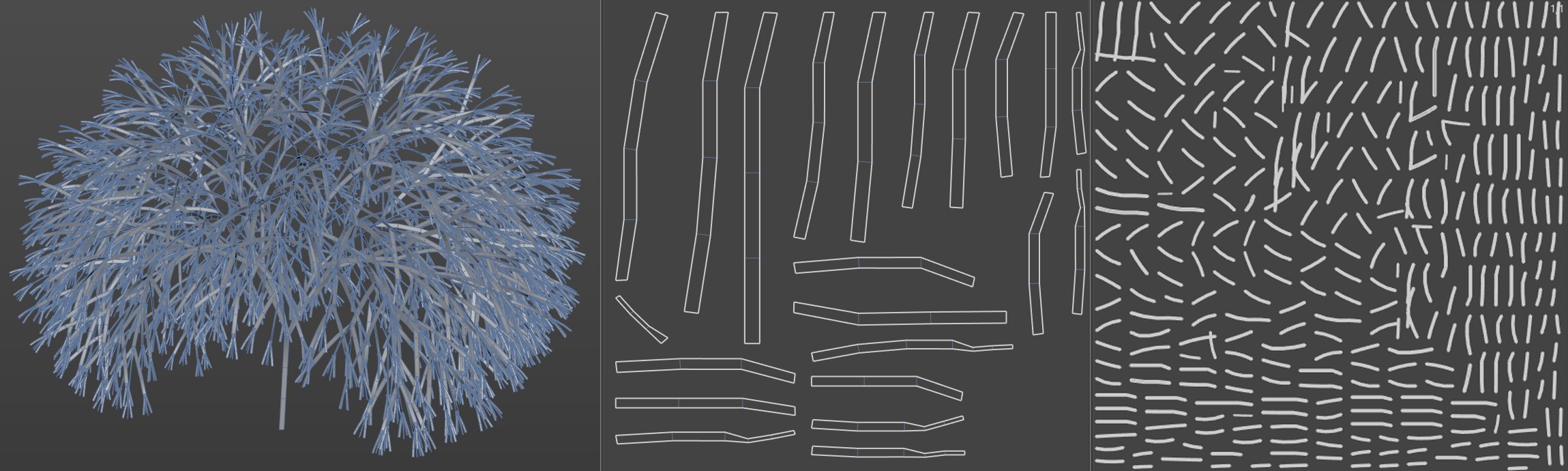 Center: Overlay Identical Geometry activated, right deactivated. This option was able to reduce this tree (originally Turtle MoSpline in a sweep object) to its recurring polygon strips and stack similar UV islands on top of each other.
If this option is activated, Cinema 4D tries to detect identical UV islands based on identical geometry and to stack them congruently on top of each other. Identical geometry thus receives identical texture. This works well with generated, similar or cloned objects.
If this option is deactivated, each polygon strip has its own UV area.
Overlay Mirrored Geometry
If the option is activated, the algorithm attempts to recognize identical but mirrored UV islands based on mirrored geometry and to stack them congruently on top of each other. This works better with "hard surface modelling" (technical objects) and less well with organic shapes.
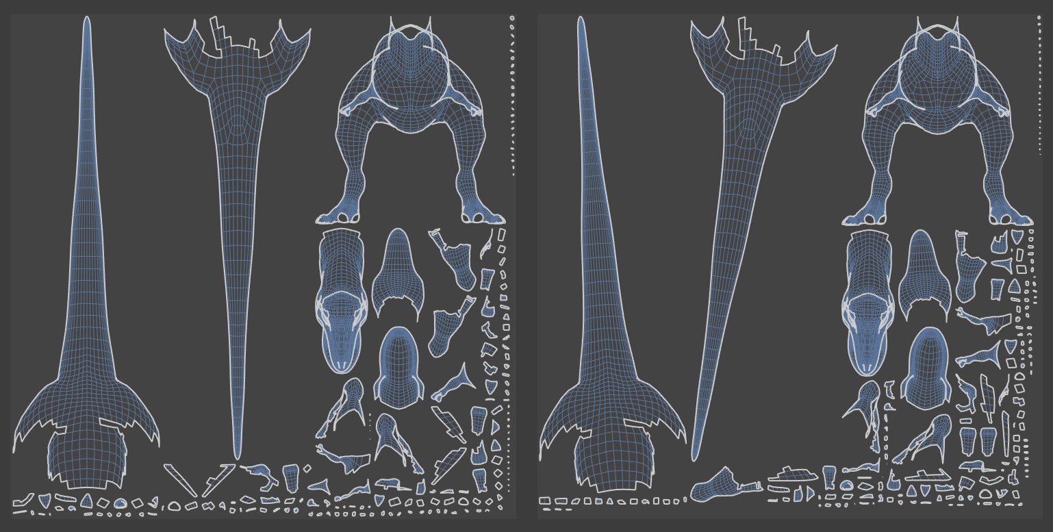 Preserve orientation option activated on the left, deactivated on the right
If you activate this option, the algorithm does not attempt to arrange each polygon group in the optimum orientation. This saves time when calculating the UV polygon position. UV islands are therefore not rotated when this option is activated, but at most scaled.
 Left deactivated, right activated option Stretch to it
If this option is activated, the UV islands are scaled independently of each other in the U and V directions so that they occupy the largest possible UV area (taking the Spacing option into account).
If the option is deactivated, scaling is only performed proportionally in both axes.
2D
If this option is activated, another algorithm (Area Factor has no influence) starts with the first UV polygon and checks whether it overlaps with another one. If yes, a new UV polygon group is created and the following UV polygons are added to it, if not, nothing happens. All UV polygons are checked in this way.