Object Properties
 The points of a cube and a disk are recorded by the Tracer as they move.
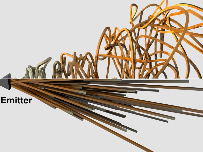
From the Object Manager, drag in the objects whose points (polygonal objects or splines) or particles are to be taken into account by the Tracer. To evaluate particles, drag either the emitter (Cinema 4D) or the particle group (Thinking Particles settings) into the field.
Please note that PLA or even pose mixer animations also work in this context, which can certainly be used to achieve one or two nice effects.
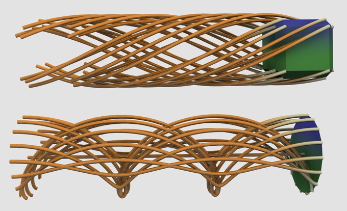
 Top: Connect All Objects mode, bottom: Trace Paths for a Particle Emitter.
The trajectory of animated object points/particles is generated as a spline.
Objects/particles (object points are also connected depending on the mode Handle Cloners objects or Traced object) are connected to a segment by a common spline.
For example, splines can be created with the help of Null objects:
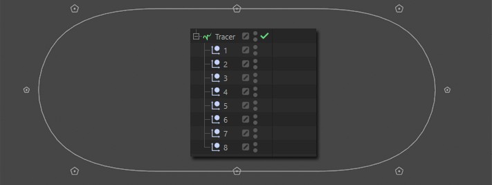
This spline could in turn be transformed into a caterpillar chain, for example, using the Cloner object. When animating the caterpillar chain, the Null objects can be controlled more easily than would be the case indirectly via a PLA spline animation.
There are also attractive effects when cloned objects (in this case spheres) are processed in this mode:
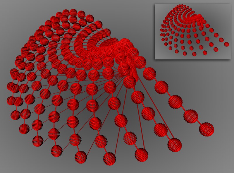 Some cloned spheres in Connect All Objects or Connect Elements mode (top right).
The objects/particles (object points are also connected depending on the mode Handle Cloners or Traced object) of different objects traced by the same Tracer are connected by a common spline, but with different segments.
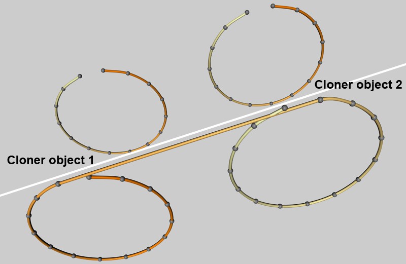 Here, 2 Cloner objects are located in a common Tracer (which in turn is located in a sweep object). Connect Elements mode at the top, Connect All Objects mode at the bottom.
Define here the number of frames of an animation after which an internal spline point is created. With the best value of 1, one point is created for each image.
If you want to switch off the Tracer temporarily, you can do so with this option. This creates gaps in the splines and thus spline segments.
If you are tracing splines or polygonal objects, use this option to decide whether all object or spline points should be recorded (active) or only the object center point (deactivated).
Since you can divide particles into groups as you wish in the Thinking Particles, use this option to define whether any subgroups of the particle group in the Tracer Link field should also be recorded.
If you nest several Cloner objects inside each other, the Tracer must know how to proceed with the clones of Cloner objects. You can select from the following:
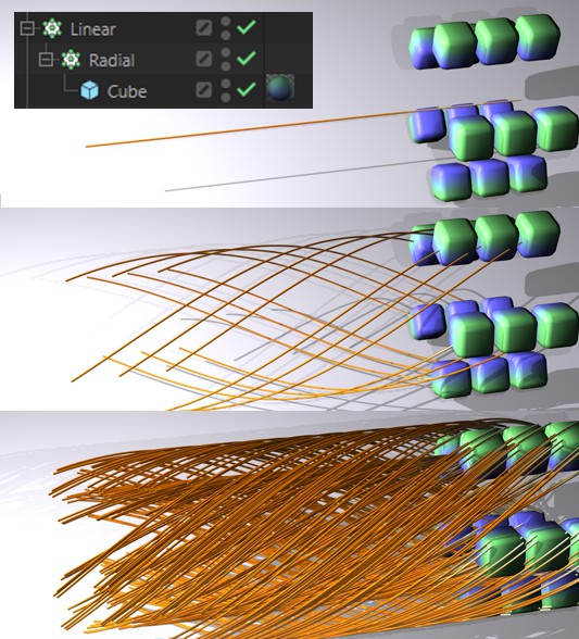 From top to bottom Nodes Only, Immediate Clones and Clones of Clones. Trace Vertices option activated in each case. Top left: the hierarchy of objects. The Tracer tracks the Linear Cloner object, which is animated from left to right.
Only the Cloner object that is located directly in the Tracer Link field is taken into account. If this Cloner object has other Cloner objects as Child objects, these are ignored.
If the Cloner object in the Tracer Link field has other Cloner objects as direct Child objects, these are taken into account.
All clones that the Cloner object in the Tracer Link field has as Child objects are taken into account.
If the origin of the Cloner object itself (not the clones) is also to be taken into account as a spline point during internal spline generation, this option must be activated. In most cases, however, this should not be necessary.
You can position the Tracer and the object to be recorded as required. Depending on which of the two options you select here, the following will happen:
The spline tracks are virtually pulled out from under the feet, i.e., if you move the Tracer object, this has a rather effective effect on the spline tracks. The object to be traced does not have to be moved at all, as the surrounding space is shifted in this way. In this mode you do not have to worry about different positions of the Tracer object and the object to be traced, it will always work perfectly.
The traced splines are positioned relative to the Tracer object: Only if the Tracer is located at position 0,0,0 do the spline tracks match the traced object exactly, otherwise the spline tracks appear at the distance at which the Tracer object is removed from the world origin. To cut a long story short: In certain situations, such as when you trace an emitter and pack it into a Loft object, this can be influenced more easily or more directly by Tracer movements.
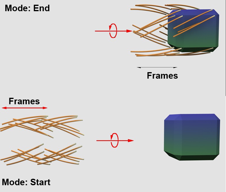 Such effects occur in different Limit modes when the cube moves from left to right.
This limits the spline length as follows:
No limit, movements are completely chiseled in splines.
Splines are generated from the start of the animation for as long as you set frames with the parameter that then appears on the right.
The moving object or particle drags a spline trail behind it. You specify the length of this sequence in animation images. The corresponding Amount parameter is displayed below the selection menu.
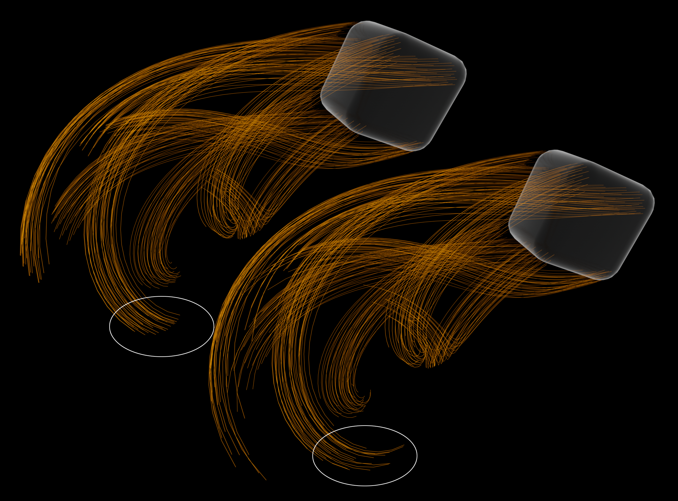 The spline lengths are varied randomly, left Variance = 0, right 4.
Variance results in random changes in the length of the splines. The value entered here is added/subtracted to Number and the spline length is varied randomly within the resulting time period.
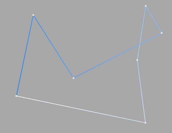
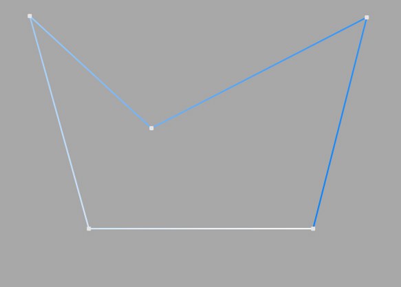
This simplest of all spline types connects the support points that define the polygon using direct connecting lines. You can use these splines to create angular objects or to simulate choppy movements during animation.
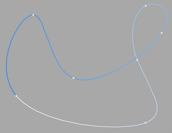
This type of spline creates a smooth curve between the interpolation points. The interpolated curve always passes exactly through the interpolation points.
You can see from the two points at the top right that the curve extends further to the top right than is actually necessary. This behavior is called overshoot and often occurs on tight bends. This becomes particularly clear when you compare this curve section with the same section in the Akima interpolation.
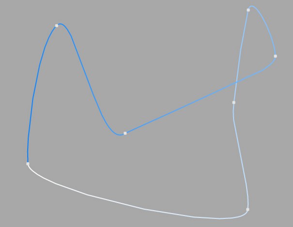
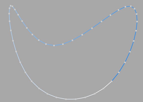
This type of spline creates a smooth curve between the interpolation points. The interpolated curve always passes exactly through the interpolation points. There is no overshoot here.
This type of interpolation adheres very closely to the curve specified by the interpolation points, but can sometimes appear a little too hard as a result. In such a case, switch to Cubic interpolation.
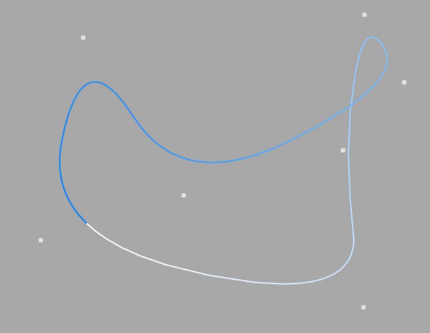
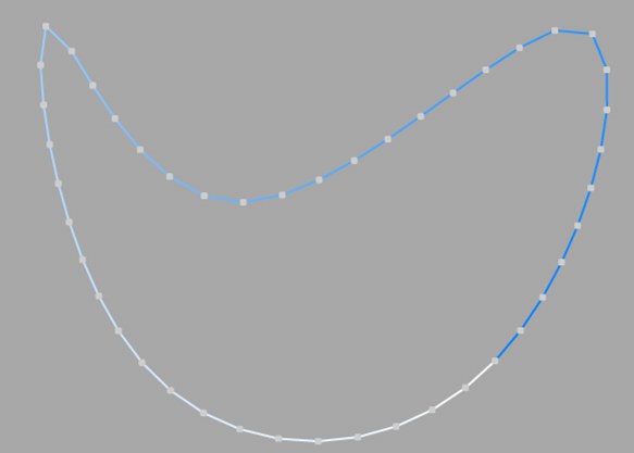
This type of spline creates a smooth curve between the interpolation points. With this type of interpolation, the curve does not pass through the interpolation points.
The spline created in this way is extremely smooth. The interpolation points only check the approximate course of the curve. Points that are further apart have less influence on the course of the curve than points that are close together.
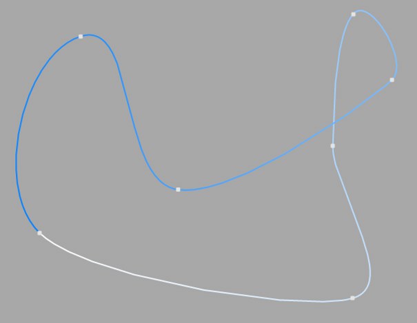
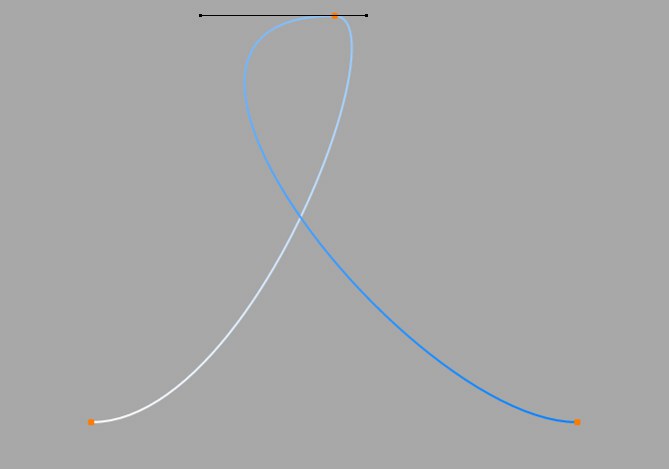
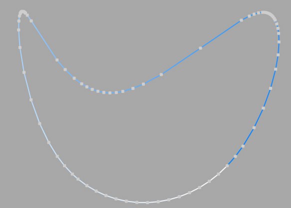
This type of spline creates a smooth curve between the support points, which can be controlled very precisely. The interpolated curve always passes exactly through the interpolation points. Overshoot does not occur. If you activate a support point of the spline (i.e. click on it), additional control points on tangents become visible.
You can use the direction of the tangents to precisely define the course of the curve gradient at each interpolation point. To do this, click on a tangent end point and move it with the mouse.
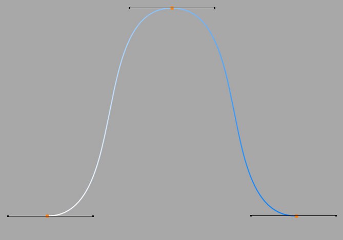
You can control the strength of the curvature with the length of the tangents. To do this, move one tangent end point in the direction of the spline support point (the other also approaches the support point symmetrically).
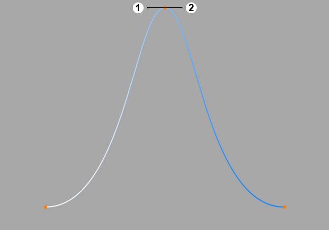
In the figures above, all tangents are horizontal. From here, the tangent of the upper point has been rotated by 180°, i.e. the left tangent end point is now on the right, the right one on the left. You can see the result in the following illustration.
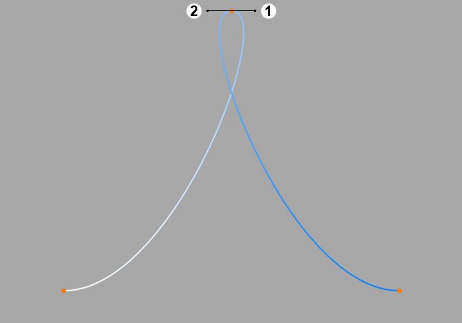
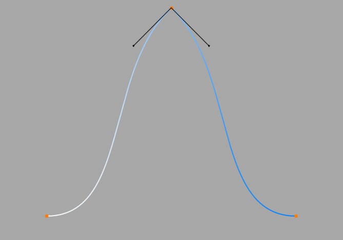
You can determine the lengths of the tangents separately. Hold down the Shift key while clicking and dragging a tangent end point. You can see an example of this in the following illustration.
You can specify different tangent directions to the right and left of the base point. This gives the otherwise smooth curve corners and peaks. Hold down the Shift key, click on a tangent end point and move it with the mouse.
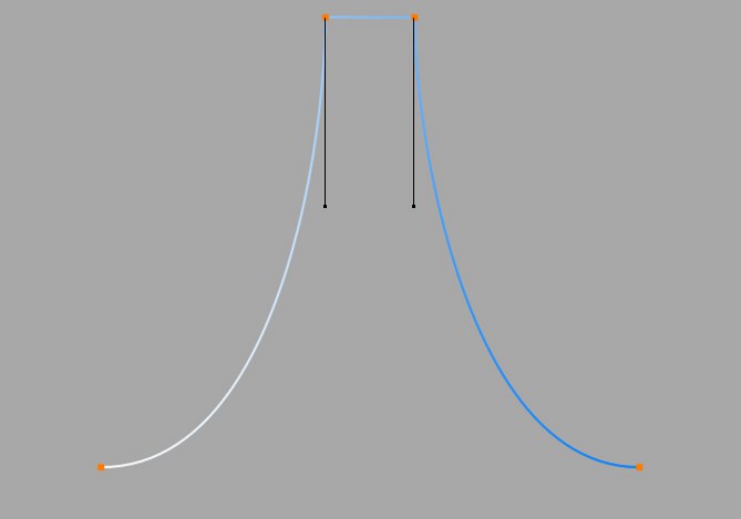
If the tangents of two neighboring points have a length of 0, the line segment between the two interpolation points is linear. You can therefore even mix linear segments with spline shapes.
If you double-click on a Bezier support point with the Move, Scale or Rotate tool activated, a dialog box opens in which you can enter the exact numerical position of both the support point (in the object coordinate system of the spline) and the tangent end points (relative to the support point).
If you convert a Bezier spline to another spline type, all tangents are lost. In the opposite case, the tangents are created to fit.
Compared to the other spline types, Bezier splines offer you the most control options. Cinema 4D therefore uses Bezier splines for the animation without exception.
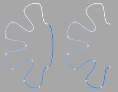 Closed spline on the left, open spline on the right
Each spline can be closed or open. If a spline is closed, the start and end points are connected.
There is a difference whether you close a spline or whether you select identical start and end points. In the first case, the transition from start to end point is smooth, in the second case it is abrupt.
You can close a spline automatically when you create it by clicking on the starting point at the end (the Ctrl/Cmd key must also be held down here).
Here you set how the spline is to be subdivided during further processing. This is always important when you generate meshes with the help of generators. Depending on which type you select from the menu for Interpolation, you have further options.
This type of interpolation uses the interpolation points of the spline directly and connects them via straight lines without setting additional intermediate points.
You cannot make entries in the fields for Points or Angle.
This type of interpolation divides the spline in such a way that a corresponding number of Points are used per interpolation point. The inserted points follow the natural course of the spline directly, i.e. they are closer together at support points than in between. The curve resulting from this interpolation does not necessarily pass through the interpolation points. If a spline has several segments, the value for Points applies to each interpolation point of each segment.
You cannot make any entries in the Angle field.
This interpolation type divides the spline so that the selected number of Points is used for each interpolation point. The points are exactly the same distance apart. The curve resulting from this interpolation does not necessarily pass through the interpolation points. If a spline has several segments, the value for Points applies to each interpolation point of each segment.
You cannot make any entries in the Angle field.
Opened spline: ((Points + 1) * (number_of_base_points - 1)) +1
Closed spline: (Points + 1) * number_of_base_points
This means, for example, that an open spline with four support points and a Points value of 2 is divided into a total of ((2+1)*(4-1))+1 = 10 points. If you close this spline, (2+1)*4 = 12 points are used. This procedure prevents, for example, a spline from being split more roughly after it has been closed.
This type of interpolation always sets intermediate points if the angular deviation of the curve is greater than the value entered under Angle. The curve resulting from this interpolation passes exactly through the interpolation points. If a spline has several segments, the value for Angle applies to each segment.
In contrast to the other interpolation types, different interpolations result if you change the interpolation point sequence of the spline.
The subdivision, also known as Adaptive, produces the best results in rendering. This is therefore the default Interpolation method.
You cannot make any entries in the Points field.
Subdivided is similar to the Adaptive type. In addition, intermediate points are inserted until the segments in between are shorter than the length defined under Max Length. This does not necessarily mean that the point distances correspond exactly to Max Length. Smaller values lead to higher quality, but as is so often the case, they also have the disadvantages associated with high point counts (slower redraw speed in the editor, etc.).
This enables significantly better rendering quality, especially with deformed text. If you enter the same value for Max Length as for Size in the Extrude object (Caps tab, Regular Grid option activated), you will get fairly perfect cap areas and edges without shading errors, as the subdivisions of letters and their caps fit together and triangles do not have to be inserted arbitrarily to connect the two mesh elements.
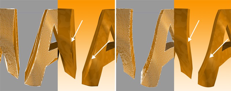 On the left Adaptive, on the right Subdivided Interpolation in combination with a Formula deformation object. Note the clearly defined edges on the right-hand side of the illustration.
This parameter, which is only effective in Subdivided Interpolation mode, controls the maximum spline segment length without an intermediate point (see above for Subdivided) must be inserted.
If you want to reverse the point order of the internal spline, activate this option.