Connector Tag
The task of the connector is - as the name suggests - to connect objects within the simulation system. This can in part also be the Cloth Belt and Rope Belt tag but this would connect simulated objects with non-simulated objects.
The connector tag, on the other hand, connects simulated objects to each other, e.g.,, Cloth tag-wearing objects to other Cloth / Rope tag-wearing objects. In the following scene the horizontal rope is attached to an end point and the rest of the system moves in accordance with opposing forces.

In this scene there are 4 splines: the rope hanging crosswise, and the 3 vertical ropes from which the cubes hang. The 3 vertical splines each have a Connector tag assigned to them. This creates Connector constraints (in yellow in the video); these ensure that the vertical splines connect with the cross rope at the top and one cube each (alternatively, all 4 splines can also be combined into one, in which case you must activate the Same Object option in the Connector tag so that the spline segments can connect).
The Connector object has the following special properties:
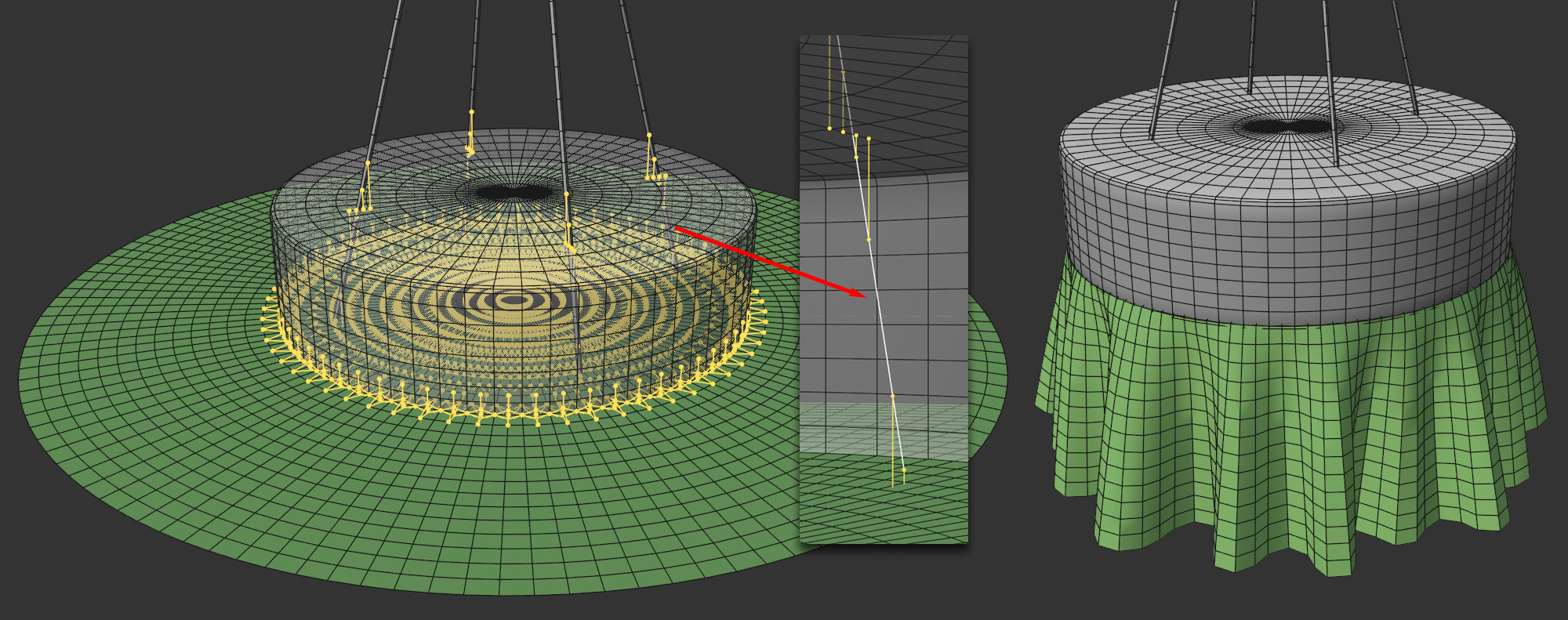
- Connector Constraints are created based on controllable distances, i.e., the distance from one point to another defines whether a constraint should be created there.
- Constraints can also be created at points within the same object. Here you can affect the folds or create stiffness.
- Connector constraints can tear at a certain elongation.
- Collision detection between connected points is disabled (so that for a close connection Target Length can be set to 0 and positioning can be done from point to point).
Operation
After assigning the Connector tag, the corresponding constraints must first be created. To do so, click on the Create button in the Tag tab. If Search Radius is large enough, Constraints will be created between the points and displayed as yellow lines in the Viewport: by default always when the tag is selected.
In addition, some parameters have no function with rigid bodies, e.g., Max. Connections (for Rigid Body to Rigid Body), Point Restriction or Same Object.
Otherwise, the connectors will behave as described here.
Tips and Tricks
When connecting Rigid Bodies with ropes or clothing, it is possible to avoid visible gaps by allowing rope splines or clothing meshes to protrude into the Rigid Body (in previous versions, these objects could not overlap without problems). If connectors are active, connected points will be ignored with regard to collisions. In such cases, overlaps will not be a problem.